Display Panels
NOT AVAILABLE ON HDMI OR VGA VERSIONS
The PicoMite firmware includes support for many LCD display panels using an SPI, I2C or parallel interface. These commands must be entered at the command prompt (not in a program) and will cause the PicoMite firmware to restart. This has the side effect of disconnecting the USB console interface which will need to be reconnected.
Note that the maximum voltage on all the Raspberry Pi Pico’s I/O pins is 3.3V. Level shifting will be required for displays that use 5V levels for signalling. The Raspberry Pi Pico 2 can tolerate 5V (while powered) so, in this case, level shifting is not required.
System SPI Bus
The system SPI bus is a dedicated SPI channel which is used by many LCD panels, all touch controllers and also to communicate with a SD Card. If any of these are attached the I/O pins used for the system SPI bus must be defined first.
This is done using this command:
OPTION SYSTEM SPI CLK-pin, MOSI-pin, MISO-pin
This must be entered at the command prompt and will cause the firmware to restart and disconnect the USB console interface, which will need to be reconnected. This option will be reapplied on startup and the pins will be reserved and not be available for other uses.
A typical example is:
OPTION SYSTEM SPI GP18, GP19, GP16
Note that the speed of drawing to SPI based displays and accessing SD cards is not affected by the CPU speed.
SPI Based Display Panels
These display panels are configured using the following commands. All require that the system SPI bus (see above) has been defined first.
In all commands the parameters are:
| Parameter | Description |
|---|---|
| OR | This is the orientation of the display and it can be LANDSCAPE, PORTRAIT, |
| RLANDSCAPE or RPORTRAIT. These can be abbreviated to L, P, RL or RP. The R prefix | |
| indicates the reverse or "upside down" orientation. | |
| DC | Display Data/Command control pin. |
| RESET | Display Reset pin (when pulled low). |
| CS | Display Chip Select pin (active low). |
| BL | Optional pin used to control the backlight brightness using Pulse Width Modulation (PWM). |
| INVERT | This option will cause the colours to be inverted to compensate for a non standard panel. |
-
OPTION LCDPANEL ILI9341, OR, DC, RESET, CS [,BL] [,INVERT]Initialises a TFT display using the ILI9341 controller. This supports 320 * 240 resolution. Displays using this controller are capable of transparent text and will work with the BLIT and BLIT READ commands.
-
OPTION LCDPANEL ILI9163, OR, DC, RESET, CS [,BL] [,INVERT]Initialises a TFT display using the ILI9163 controller. This supports 128 * 128 resolution.
-
OPTION LCDPANEL ILI9481, OR, DC, RESET, CS [,BL] [,INVERT]Initialises a TFT display using the ILI9481 controller. This supports 480 * 320 resolution.
-
OPTION LCDPANEL ILI9481IPS, OR, DC, RESET,CS [,BL][,INVERT]Initialises an IPS display using the ILI9481 controller. This supports 480 * 320 resolution.
-
OPTION LCDPANEL ILI9488, OR, DC, RESET, CS [,BL] [,INVERT]Initialises a TFT display using the ILI9488 controller. This supports 480 * 320 resolution. Note that this controller has an issue with the MISO pin which interferes with the touch controller. For this display to work the MISO pin must not be connected.
-
OPTION LCDPANEL ILI9488P, OR, DC, RESET, CS [,BL] [,INVERT]Initialises a TFT display using the ILI9488 controller. This supports 320 * 320 resolution. Note that this controller has an issue with the MISO pin which interferes with the touch controller. This configuration supports the PicoCalc with the display in portrait mode.
-
OPTION LCDPANEL ILI9488W, OR, DC, RESET, CS [,BL] [,INVERT]Initialises a TFT display using the ILI9488 controller. This supports the Waveshare 3.5" display as used on their Pico Eval board and the normal 3.5" display adapter.
-
OPTION LCDPANEL N5110, OR, DC, RESET, CS [,contrast] [,INVERT]Initialises a LCD display using the Nokia 5110 controller. This supports 84 * 48 resolution. An additional parameter ‘contrast’ may be specified to control the contrast of the display. Try contrast values between &HA8 and &HD0 to suit your display, default if omitted is &HB1
-
OPTION LCDPANEL SSD1306SPI, OR, DC, RESET, CS [,offset] [,INVERT]Initialises a OLED display using the SSD1306 controller with an SPI interface. This supports 128 * 64 resolution. An additional parameter ‘offset’ may be specified to control the position of the display. 0.96" displays typically need a value of 0. 1.3" displays typically need a value of 2. Default if omitted is 0.
-
OPTION LCDPANEL SSD1331, OR, DC, RESET, CS [,BL] [,INVERT]Initialises a colour OLED display using the SSD1331 controller. This supports 96 * 64 resolution.
-
OPTION LCDPANEL ST7735, OR, DC, RESET, CS [,BL] [,INVERT]Initialises a TFT display using the ST7735 controller. This supports 160 * 128 resolution.
-
OPTION LCDPANEL ST7735S, OR, DC, RESET, CS [,BL] [,INVERT]Initialises a IPS display using the ST7735S controller. This supports 160 * 80 resolution.
-
OPTION LCDPANEL ST7735S_W, OR, DC, RESET, CS [,BL][,INVERT]Initialises a Waveshare 128x128 ST7735S display. This supports 128 * 128 resolution.
-
OPTION LCDPANEL ST7789, OR, DC, RESET, CS [,BL] [,INVERT]Initialises a IPS display using the 7789 controller. This supports 240 * 240 resolution. NOTE: display boards without a CS pin are not currently supported in the PicoMite firmware unless modified.
-
OPTION LCDPANEL ST7789_135, OR, DC, RESET,CS [,BL][,INVERT]Initialises a IPS display using the 7789 controller. This supports 240 * 135 resolution.
NOTE: display boards without a CS pin are not currently supported in the PicoMite firmware unless modified. -
OPTION LCDPANEL ST7789_320, OR, DC, RESET,CS [,BL][,INVERT]Initialises a IPS display using the 7789 controller. This type supports the 320 * 240 resolution display from Waveshare ( https://www.waveshare.com/wiki/Pico-ResTouch-LCD-2.8 ).
These are capable of transparent text and will work with the BLIT and BLIT READ commands.
NOTE: display boards without a CS pin are not currently supported in the PicoMite firmware unless modified.
-
OPTION LCDPANEL ST7796S, OR, DC, RESET,CS [,BL][,INVERT]Initialises a IPS display using the ST7796S controller. This supports 480 * 320 resolution.
NOTE: In order for transparent test and blit to work properly the diode D1 on the back of the display should be bridged and it is recommended that J1 is also bridged to run on 3.3V
-
OPTION LCDPANEL ST7796SP, OR, DC, RESET,CS [,BL][,INVERT]Initialises a TFT display using the ST7796S controller. This supports 320 * 320 resolution. This configuration supports the PicoCalc with the display in portrait mode.
-
OPTION LCDPANEL GC9A01, OR, DC, RESET, CS [,BL] [,INVERT]Initialises a IPS display using the GC9A01 controller. This supports 240 * 240 resolution.
-
OPTION LCDPANEL ST7920, OR, DC, RESETInitialises a LCD display using the ST7920 controller. This supports 128 * 64 resolution. Note this display does not support a chip select so the SPI bus cannot be shared if this display is used.
I2C Based LCD Panels
All I2C based display controllers use the system I2C pins as per the pinout for the specific device. Other I2C devices can share the bus subject to their addresses being unique.
To setup the system I2C bus use the command:
OPTION SYSTEM I2C sdapin, sclpin
If an I2C display is configured it will not be necessary to "open" the I2C port for an additional device (I2C OPEN), I2C CLOSE is blocked, and all I2C devices must be capable of 100KHz operation. The I2C bus speed is not affected by changes to the CPU clock speed.
These panels are configured using the following commands. In all commands the parameters OR is the orientation of the display and it can be LANDSCAPE, PORTRAIT, RLANDSCAPE or RPORTRAIT. These can be abbreviated to L, P, RL or RP. The R prefix indicates the reverse or "upside down" orientation.
-
OPTION LCDPANEL SSD1306I2C, OR [,offset]Initialises a OLED display using the SSD1306 controller with an I2C interface. This supports 128 * 64 resolution. An additional parameter offset may be specified to control the position of the display. 0.96" displays typically need a value of 0. 1.3" displays typically need a value of 2. Default if omitted is 0. NB many cheap I2C versions of SSD1306 displays do not implement I2C properly due to a wiring error. This seems to be particularly the case with 1.3" variants -
OPTION LCDPANEL SSD1306I2C32, ORInitialises a OLED display using the SSD1306 controller with an I2C interface. This supports 128 * 32 resolution.
8-bit Parallel LCD Panels
In addition to the SPI and I2C based controllers the PicoMite firmware supports LCD displays using the SSD1963 controller (as illustrated) and the ILI9341 controller.
These use a parallel interface, are available in sizes from 2.8" to 9" and have better specifications than the smaller displays. All these displays have an SD Card socket which is fully supported by MMBasic. On eBay you can find suitable displays by searching for the controller’s name (eg SSD1963).
Because they use a parallel interface data can be transferred much faster than an SPI interface resulting in a very quick screen update.
The characteristics of these displays are:
- A 2.8, 3.2, 4.3, 5, 7, 8 or 9 inch display
- Resolution of 320 x 240, 480 x 272 pixels (4.3" version) or 800 x 480 pixels (5”, 7", 8" or 9" versions).
- An SSD1963 display controller or ILI9341 display controller with a parallel interface (8080 format)
- A touch controller (SPI interface).
- A full sized SD Card socket.
There are a number of different designs using the SSD1963 controller but fortunately most suppliers have standardised on a single connector as illustrated on the right.
It is strongly recommended that any display purchased has a matching connector
– this provides some confidence that the manufacturer has followed the standard
that the PicoMite firmware is designed to use.
Connecting an 8-bit parallel LCD Panel
The controller uses a parallel interface while the touch controller and SD Card use an SPI interface. The touch and SD Card features are optional but if they are used they will use the second SPI port (SPI2).
The following table lists the connections required between the display board and the Raspberry Pi Pico to support the 8-bit parallel interface and the LCD display. The touch controller and SD Card interfaces are listed below.
| 8-bit parallel Display | Description | Raspberry Pi Pico |
|---|---|---|
| DB0 | Parallel Data Bus bit 0 | Pin 1/GP0 |
| DB1 | Parallel Data Bus bit 1 | Pin 2/GP1 |
| DB2 | Parallel Data Bus bit 2 | Pin 4/GP2 |
| DB3 | Parallel Data Bus bit 3 | Pin 5/GP3 |
| DB4 | Parallel Data Bus bit 4 | Pin 6/GP4 |
| DB5 | Parallel Data Bus bit 5 | Pin 7/GP5 |
| DB6 | Parallel Data Bus bit 6 | Pin 9/GP6 |
| DB7 | Parallel Data Bus bit 7 | Pin 10/GP7 |
| CS | Chip Select (active low) | Ground (ie, always selected) |
| WR | Write (active low) | Pin 19/GP14* |
| RD | Read (active low) | Pin 20/GP15* |
| DC | Command/Data | Pin 17/GP13* |
| RESET | Reset the SSD1963 | Pin 21/GP16* |
| LED_A | Backlight control for an unmodified display panel | Configurable see OPTION LCDPANEL |
| 5V | 5V power for the backlight on some displays (most displays use the 3.3V supply for this) | |
| 3.3V | Power supply. | |
| GND | Ground |
* Pins DC, WR, RD, RESET can be allocated to other pins as a block of 4 using the optional parameter DCpin
The following table lists the connections required to support the touch controller interface: 8-bit parallel
| Display | Raspberry Pi Pico | Description |
|---|---|---|
| T_CS | Touch Chip Select | Recommended Pin 24/GP18 |
| T_IRQ | Touch Interrupt | Recommended Pin 25/GP19 |
| T_DIN | Touch Data In (MOSI) | Recommended Pin 15/GP11 |
| T_CLK | Touch SPI Clock | Recommended Pin 14/GP10 |
| T_DO | Touch Data Out (MISO) | Recommended Pin 16/GP12 |
The following table lists the connections required to support the SD Card connector:
| 8-bit parallel Display | Description | Raspberry Pi Pico |
|---|---|---|
| SD_CS | SD Card Chip Select | Recommended Pin 29/GP22 |
| SD_DIN | SD Card Data In (MOSI) | Recommended Pin 15/GP11 |
| SD_CLK | SD Card SPI Clock | Recommended Pin 14/GP10 |
| SD_DO | SD Card Data Out (MISO) | Recommended Pin 16/GP12 |
Where a connection is listed as "Recommended" this is only a suggestion and other pins can be used depending on the hardware configuration. Regardless, the specific pin should be specified in the appropriate OPTION command (see below).
Generally 7 inch and larger displays have a separate pin on the connector (marked 5V) for powering the backlight from a 5V supply. If this pin is not provided the backlight power will be drawn from the 3.3V pin. Note that the power drawn by the backlight can be considerable. For example, a 7 inch display will typically draw 330 mA from the 5V pin.
If the Pico’s 3,3V output is used for powering a panel plus its backlight, it may easily require more current than the Pico can supply. Symptoms of a marginal supply could include TOUCH calibration failures or SD access failures. In this case an external 3.3V supply should be used.
The current drawn by the backlight can also cause a voltage drop on the LCD display panel’s ground pin which can in turn shift the logic levels as seen by the display controller resulting in corrupted colours or text. An easy way of diagnosing this effect is to reduce the CPU speed to (say) 48MHz. If this fixes the problem it is a strong indication that this is the cause. Soldering power and ground wires direct to the LCD display panel’s PCB is one workaround.
Care must be taken with display panels that share the SPI port between a number of devices (SD Card, touch, etc).
In this case all the Chip Select signals must configured in MMBasic or disabled by a permanent connection to 3.3V. If this is not done the pin will float causing the wrong controller to respond to commands on the SPI bus.
In the PicoMite firmware either SPI channel can used to communicate with the touch controller and the SD Card interface as defined by the OPTION SYSTEM SPI setting. If this is set, that SPI channel will be unavailable to BASIC programs (which can use the other SPI channel).
Configuring an 8-bit parallel LCD Panel
To use the display MMBasic must be configured using the OPTION LCDPANEL command which is normally entered at the command prompt. Every time the PicoMite firmware is restarted MMBasic will automatically initialise the display.
The syntax is:
OPTION LCDPANEL controller, orientation [,backlightpin] [,DCpin] [,NORESET] [DB0pin]
Where 'controller' can be either:
- SSD1963_4 : For a 4.3 inch display
- SSD1963_5 : For a 5 inch display
- SSD1963_5A : For an alternative version of the 5 inch display if SSD1963_5 does not work
- SSD1963_7 for a 7 inch display
- SSD1963_7A for an alternative version of the 7 inch display if SSD1963_7 does not work.
- SSD1963_8 for 8 inch or 9 inch displays.
- ILI9341_8 for a 2.8” or 3.2” display
orientation can be LANDSCAPE, PORTRAIT, RLANDSCAPE or RPORTRAIT. These can be abbreviated to
L, P, RL or RP. The R prefix indicates the reverse or "upside down" orientation.
DCpin is optional and is the Data/Command pin (previously called the RS pin). If this parameter is omitted the pin assignment will be as above in the table. If it is specified then DC, WR, RD and RESET pins will be assigned sequentially from DC pin.
The optional NORESET parameter can be used to save a pin. In this case the reset pin should be tied high. The optional DB0pin is only applicable to the RP2350B and can be used to specify the start pin for the 8 or 16 consecutive data pins used by the display.
This command only needs to be run once. From then on MMBasic will automatically initialise the display on
startup or reset. In some circumstances it may be necessary to interrupt power to the LCD panel while the
PicoMite firmware is running (eg, to save battery power) and in that case the GUI RESET LCDPANEL
command can be used to reinitialise the display.
If the LCD panel is no longer required the command OPTION LCDPANEL DISABLE can be used which will
return the I/O pins for general use.
To verify the configuration you can use the command OPTION LIST to list all options that have been set
including the configuration of the LCD panel.
To test the display you can enter the command GUI TEST LCDPANEL. You should see an animated display of colour circles being rapidly drawn on top of each other. Press the space bar on the console’s keyboard to stop the test.
8 and 9 inch Displays
The controller configuration SSD1963_8 has only been tested with the 8 and 9 inch displays made by EastRising (available at http://www.buydisplay.com). These must be purchased as a TFT LCD panel with 8080 interface, 800x480 pixel LCD, SSD1963 display controller and XPT2046 touch controller.
Note that the EastRising panels use a non-standard interface connector pin-out so you will need to refer to their data sheets when connecting these to the Raspberry Pi Pico. A suitable adapter to convert to the standard 40-pin connection can be purchased from: https://www.rictech.nz/micromite-products
16-bit Parallel LCD Panels
SSD1963 panels can also be enabled for 16-bit parallel operation. In this case, by default, pins GP0-GP15 are used for the data connections and, by default, pins GP16 to GP19 are used for the control signals DC, WR, RD and RESET.
For systems using the RP2350B only the data pins used can be selected by using the optional DB0pin parameter in the configuration command. To enable 16-bit operation append “_16” to the controller. Eg, SD1963_4_16.
The firmware also supports ILI9341, ILI9486, NT35510 and OTM8009A panels in 16-bit mode using the controller types ILI9341_16, ILI9486_16, and IPS_4_16 (supports both NT35510 and OTM8009A).
Valid 16-bit 'controllers' can be:
SSD1963_4_16For a 4.3 inch displaySSD1963_5_16For a 5 inch displaySSD1963_5A_16For an alternative version of the 5 inch display ifSSD1963_5does not workSSD1963_5ER_16For the 5 inch EastRising panelSSD1963_7_16For a 7 inch displaySSD1963_7A_16For an alternative version of the 7 inch display ifSSD1963_7does not work.SSD1963_7ER_16For the 7 inch EastRising panelSSD1963_8_16For 8 inch or 9 inch displays.ILI9341_16For a 2.8” or 3.2” displayILI9486_16Also supports NXP R61529IPS_4_16
Backlight Control
For the ILI9163, ILI9341, ST7735, ST7735S, SSD1331, ST7789, ILI9481, ILI9488, ILI9488W, ST7789_135, ILI9341_8 and ST7789_320 displays an optional parameter , backlight can be added to the end of the configuration parameters which specifies a pin to use to control the brightness of the backlight (LED_A). This will setup a PWM output on that pin with a frequency of 50KHz and an initial duty cycle of 99%.
You can then use the BACKLIGHT command to change the brightness between 0 and 100%. The PWM channel
is blocked for normal PWM use and must not conflict with the PWM channel that may be set up for audio.
For example:
OPTION LCDPANEL ILI9341, OR, DC, RESET, CS, GP11
The backlight can then be set to 40% with this command:
BACKLIGHT 40
Most SSD1963 based LCD panels have three pairs of solder pads on the PCB which are grouped under the heading "Backlight Control" as illustrated on the right.
Normally the pair marked "LED-A" are shorted together with a zero ohm resistor and this allows control of the backlight's brightness with a PWM (pulse width modulated) signal on the LED-A pin of the display panel's main connector.
However, it is better to use the SSD1963 controller to generate this signal as it frees up one I/O pin and allows finer control.
To use the SSD1963 control, the zero ohm resistor should be removed from the pair marked "LED-A" and used to short the nearby pair of solder pads marked "1963-PWM". The brightness can then be set using the
BACKLIGHT command via the SSD1963 controller (this is automatic, nothing needs to be configured).
Touch Support
Many LCD panels are supplied with a resistive touch sensitive panel and associated controller chip. MMBasic fully supports this interface and this allows many of the physical knobs and switches used in a project to be implemented as on-screen controls activated by touch.
In all cases the LCD display panel itself should be configured and tested first, then the touch feature can be configured. The touch controller uses the SPI protocol for communications and for LCD panels using the SPI protocol this has normally been previously done using the OPTION SYSTEM SPI command.
For display panels using I2C or a parallel interface the OPTION SYSTEM SPI command must be separately
used to define the system SPI bus for use by the touch controller. This command was discussed near the start of this chapter and defined in detail in the Options chapter of this manual.
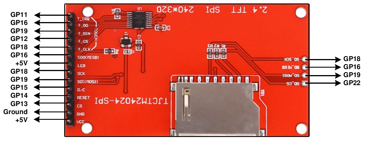
For example, using the recommended pins for an 8-bit parallel display (described above) you would use:
OPTION SYSTEM SPI GP10, GP11, GP12
To use the touch facility MMBasic must be told that the touch controller is available on the system SPI bus by using the OPTION TOUCH command. This tells MMBasic what pins are used for the Chip Select and Interrupt signals.
As an example, for a typical ILI9341 display, this sets Chip Select to the GP12 pin and Interrupt to GP11:
OPTION TOUCH GP12, GP11
This must be entered at the command prompt and will cause the firmware to restart and disconnect the USB console interface, which will need to be reconnected.
When the PicoMite firmware is restarted MMBasic will automatically initialise the touch controller. To verify the configuration, you can use the command OPTION LIST to list all options that have been set including the configuration of the display panel and touch.
Care must be taken when the SPI port is shared between a number of devices (SD Card, touch, etc). In this case all the Chip Select signals must configured in MMBasic or alternatively disabled.
Calibrating the Touch Screen
Before the touch facility can be used it must be calibrated using the GUI CALIBRATE command.
This command will present a target in the top left corner of the screen (as illustrated). Using a pointy but blunt object (such as a toothpick) press exactly on the centre of the target and hold it down for at least a second.
MMBasic will record this location and then continue the calibration by sequentially displaying the target in the other three corners of the screen for touch and calibration. The calibration routine may warn that the calibration was not accurate. This is just a warning and you can still use the touch feature if you wish but it would be better to repeat the calibration using more care.
Following calibration you can test the touch facility using the GUI TEST TOUCH command. This command will blank the screen and wait for a touch. When the screen is touched a white dot will be placed on the display marking the position on the screen. If the calibration was carried out successfully the dot should be displayed exactly under the location of the stylus on the screen. To exit the test routine you can press the space bar on the console’s keyboard.
Touch Functions To detect if and where the screen is touched you can use the following functions in a BASIC program:
TOUCH(X)Returns the X coordinate of the currently touched location or -1 if the screen is not being touched.TOUCH(Y)Returns the Y coordinate of the currently touched location or -1 if the screen is not being touched.
Touch Interrupts
An interrupt can be set on the IRQ pin number that was specified when the touch facility was configured. To detect touch down the interrupt should be configured as INTL (i.e., high to low). The interrupt can be
cancelled with the command SETPIN pin, OFF.
The following program illustrates how the touch interrupt can be used. Whenever the screen is touched it will print on the console the coordinates of that touch. It assumes that the command OPTION TOUCH 7, 15 was used to initially configure the touch function:
SETPIN 15, INTL, MyInt  ' assumes that OPTION TOUCH 7, 15 was used
DO : LOOP

SUB MyInt               ' subroutine called on a touch interrupt
PRINT TOUCH(X) TOUCH(Y)
END SUB
LCD Display as the Console Output
A PS2 or USB keyboard can be used with an LCD display panel to create a fully self contained computer that will boot direct to the MMBasic prompt. This feature works particularly well with 5 and 7 inch LCD panels using the SSD1963 controller. These can display a lot of text and update rapidly resulting in a user experience that is comparable to a PicoMite based computer using VGA or HDMI video output.
The LCD must be first configured using OPTION LCDPANEL. Then, to enable the console output on the LCD panel, you should use the following command:
OPTION LCDPANEL CONSOLE [font [, fc [, bc [, blight]]] [,NOSCROLL]
font is the default font, fc is the default foreground colour, bc is the default background colour and blight is the default backlight brightness (2 to 100). These settings are saved in flash and are used to configure MMBasic at power up. They are all optional and default to font 2, white, black and 100%.
On displays where the framebuffer cannot be read, the firmware will automatically set the NOSCROLL option. When this is set and output reaches the bottom of the screen the screen is cleared and output continues again at the top. This also applies to the in-built editor. For SPI displays that can read the framebuffer (eg ILI9341) scrolling is very slow so the NOSCROLL parameter can be set to improve output and editing performance.
Note that this isn’t necessary if the display is used in portrait mode as H/W scrolling is then used.
Colour coding in the editor is also turned on by this command (see the chapter Full Screen Editor). To disable using the LCD panel as the console the command is OPTION LCDPANEL NOCONSOLE.
Example SPI LCD Panel Configuration
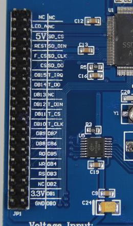
The following is a summary of how a typical LCD panel using an ILI9341 controller can be connected. This example supports the SD Card socket, the LCD display and the touch interface.
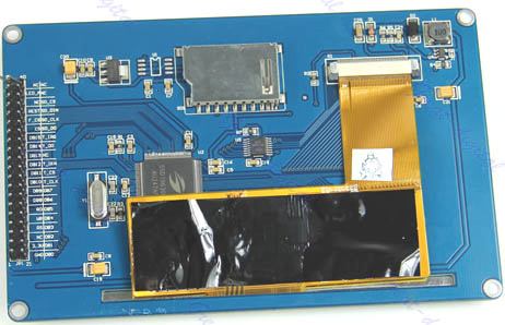
Typical panels can be found on ebay.com and similar sites by searching for the keyword “ILI9341”. Make sure that the connections on the rear of the panel resemble that shown below:
The panel should be connected to the Raspberry Pi Pico as illustrated:
To match the above connections the following configuration commands should be entered, one by one at the command prompt:
OPTION SYSTEM SPI GP18, GP19, GP16
OPTION LCDPANEL ILI9341, L, GP15, GP14, GP13
OPTION TOUCH GP12, GP11
OPTION SDCARD GP22
These commands will be remembered and automatically applied on power up. Note that after each command is entered the firmware will restart, and the USB connection will be lost and must be reconnected.
Next the touch screen should be calibrated with:
GUI CALIBRATE
You can then test the various components.
The following will draw multiple colourful overlapping circles on the LCD screen which will confirm that the LCD is connected correctly:
GUI TEST LCDPANEL
The following will test the touch interface. When you touch the LCD screen a dot should appear on the screen at the exact point of the touch.
GUI TEST TOUCH
If this is not accurate you may have to run the GUI CALIBRATE command a second time taking greater care.
Finally, the following will list the files on the SD Card, if it executes without error you can be assured that the SD Card interface is good.
FILES
If you run into trouble getting the display to work it is worth disconnecting everything and clear the options with the command OPTION RESET so that you can start with a clean slate. Then reconnect it one stage at a time and configure and test each new stage as you progress. As you do this remember that any device connected to the SPI bus must be configured in MMBasic or its chip select line must be held logic high. This is because the voltage on an unconnected chip select line will float, possibly causing the wrong device to respond to signals intended for another device.
Also note that the ILI9341 controller is very sensitive to static discharge so, if the panel will not respond, it could easily be damaged and it would be worth testing with another panel.