PicoMite
User Manual
PicoMite
A Raspberry Pi Pico Running the MMBasic BASIC Interpreter
MMBasic BASIC Interpreter
for the
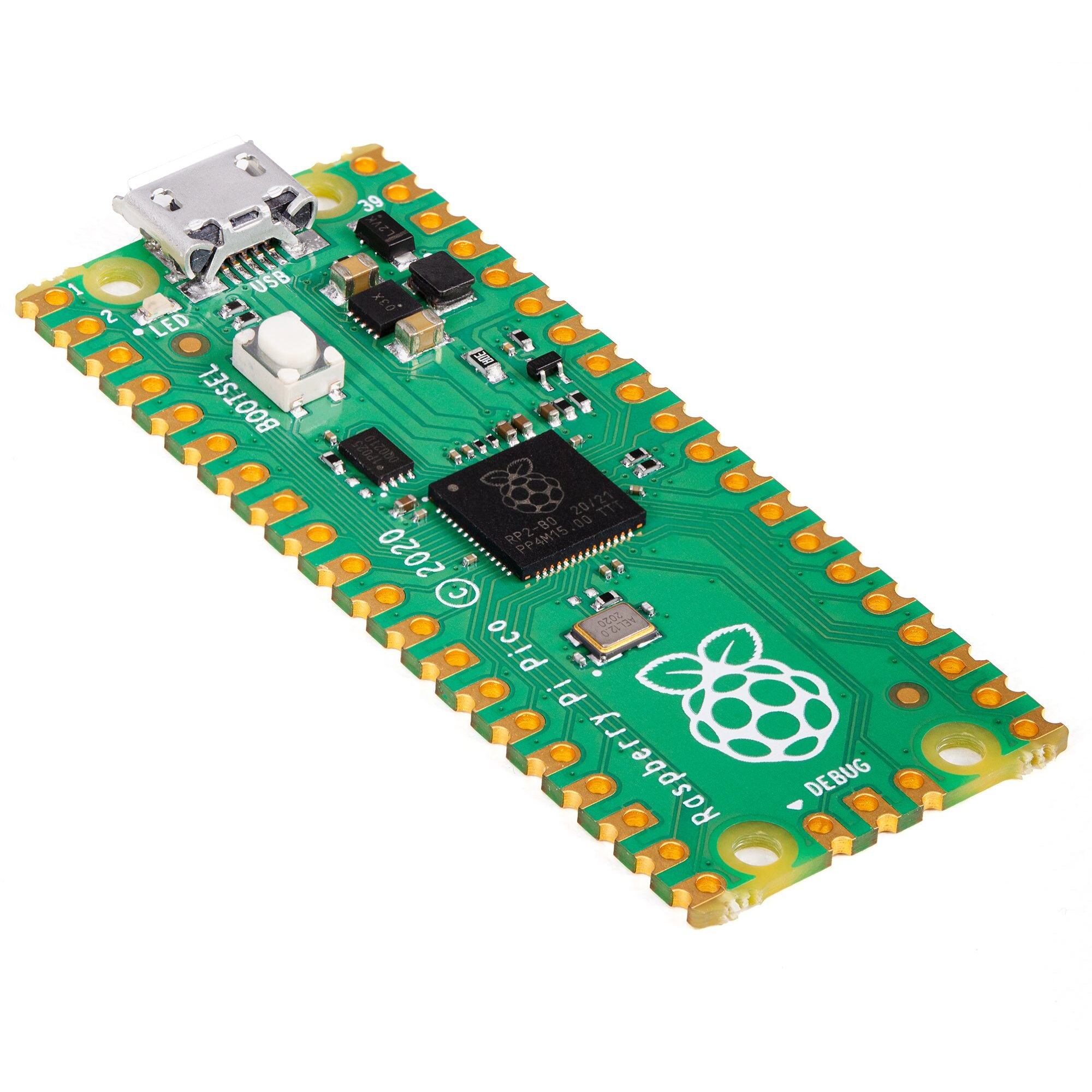
- Raspberry Pi Pico
- Raspberry Pi Pico 2
- Raspberry Pi Pico W
- Raspberry Pi Pico 2 W
- modules using the RP2040 and RP2350 processors
Ver 6.00.03 Revision 1 (18 July 2025)
For updates to this manual
For more details on MMBasic go to
This Website on Github (open to Change Requests)
About
Peter Mather (matherp on the Back Shed Forum) led the project, ported MMBasic to the Raspberry Pi Pico and wrote the drivers for its hardware features. The MMBasic interpreter and this manual was written by Geoff Graham ( http://geoffg.net ). In addition, many others have supported the project with specialised code, testing and suggestions.
Support
Support questions should be raised on the Back Shed forum ( http://www.thebackshed.com/forum/Microcontrollers ) where there are many enthusiastic MMBasic users who would be only too happy to help. The developers of the PicoMite firmware are also regulars on this forum.
Copyright and Acknowledgments
The PicoMite firmware and MMBasic is copyright 2011-2024 by Geoff Graham and Peter Mather 2016-2024.
1-Wire Support is copyright 1999-2006 Dallas Semiconductor Corporation and 2012 Gerard Sexton.
FatFs (SD Card) driver is copyright 2014, ChaN.
WAV, MP3, and FLAC file support is copyright 2019 David Reid.
JPG support is thanks to Rich Geldreich
The pico-sdk is copyright 2021 Raspberry Pi (Trading) Ltd.
TinyUSB is copyright tinyusb.org
LittleFS is copyright Christopher Haster
Thomas Williams and Gerry Allardice for MMBasic enhancements
The VGA driver code was derived from work by Miroslav Nemecek
The CRC calculations are copyright Rob Tillaart
The compiled object code (the .uf2 file) for the PicoMite firmware is free software: you can use or redistribute it as you please. The source code is on GitHub ( https://github.com/UKTailwind/PicoMiteAllVersions ) and can be freely used subject to some conditions (see the header in the source files).
This program is distributed in the hope that it will be useful, but WITHOUT ANY WARRANTY, without even the implied warranty of MERCHANTABILITY or FITNESS FOR A PARTICULAR PURPOSE.
This Manual
Copyright 2025 Geoff Graham and Peter Mather The author of this manual is Geoff Graham with input by Peter Mather, Harm de Leeuw, Mick Ames and many others on The Back Shed forum. It is distributed under a Creative Commons Attribution-NonCommercialShareAlike 3.0 Australia license (CC BY-NC-SA 3.0)
This Website
This website is made by Yamavu and distributed under CC BY-NC-SA 3.0.
Introduction
It includes a BASIC interpreter (MMBasic) which is a Microsoft BASIC compatible implementation of the BASIC language with floating point, integer and string variables, arrays, long variable names, a built in program editor and many other features.
The PicoMite firmware also supports third party boards based on the RP2040 and RP2350 and processors from companies such as Pimoroni, Adafruit and Waveshare.
There are versions of the PicoMite firmware suited for embedded controller applications (such as a heating controller, burglar alarm, etc) as well as versions with VGA/HDMI video suited to building a self contained computer with a keyboard.
Using MMBasic you can control the I/O pins and use communications protocols such as I²C or SPI to get data from a variety of sensors. You can display data on low-cost colour LCD displays, measure voltages, detect digital inputs and drive output pins to turn on lights, relays, etc. And with the Raspberry Pi Pico W you can access the internet and build a WEB server on this low cost module.
The PicoMite firmware is totally free to download and use.
In summary the features of the PicoMite firmware are:
-
The BASIC interpreter is full featured with double precision floating point, 64-bit integers and string variables, long variable names, arrays of floats, integers or strings with multiple dimensions, extensive string handling and user defined subroutines and functions. In addition, MMBasic allows the embedding of compiled C programs for high performance functions. The emphasis is on ease of use and development.
-
Support for all Raspberry Pi Pico input/output pins. These can be independently configured as digital input or output, analog input, frequency or period measurement and counting. Interrupts can be used to notify when an input pin has changed state. PWM outputs can be used to create various sounds, control servos or generate computer-controlled voltages.
-
Support for TFT LCD display panels using parallel, SPI and I²C interfaces allowing the BASIC program to display text and draw lines, circles, boxes, etc in up to 16 million colours. Resistive touch controllers on these panels are also supported allowing them to be used as sophisticated input devices.
-
Support for Internet and WEB protocols using the Raspberry Pi Pico W and Pico 2 W. This includes a WEB server using TCP and HTML, accessing other resources using TCP and HTTP. MQTT protocol for connecting via a message broker. NTP protocol for getting the date/time from a time server. Telnet for remote console access and TFTP for fast file transfer.
-
Support for a PS2 or USB keyboard and HDMI or VGA video output. This includes full support for graphics, audio (sound effects and music), internal program storage, game controllers and more. This converts the Raspberry Pi Pico or into a self-contained computer like the Apple II or Tandy TRS-80 of yesterday. Great for writing games, learning BASIC or just balancing your chequebook
-
Flexible program and data storage. Programs and data can be read/written from an internal file system created from the Pico’s flash memory or to an externally connected SD Card up to 32GB formatted as FAT16 or FAT32. This includes opening files for reading, writing or random access and loading and saving programs.
-
A full screen editor is built into the firmware and can edit the whole program in one session. It includes advanced features such as colour coded syntax, search and copy, cut and paste to and from a clipboard.
-
Programs can be easily transferred from a desktop or laptop computer (Windows, Mac or Linux) via the serial console or via an SD card.
-
A comprehensive range of communications protocols are implemented including I²C, asynchronous serial, RS232, SPI and 1-Wire. These can be used to communicate with many sensors (temperature, humidity, acceleration, etc) as well as for sending data to test equipment.
-
Built in commands to directly interface with infrared remote controls, the DS18B20 temperature sensor, LCD display modules, battery backed clock, numeric keypads and more.
Firmware Versions and Files
The PicoMite firmware can be used for two distinctly differing roles depending on the version of the firmware loaded. These roles are; a self contained computer and an embedded controller:.
Self Contained Computer
Versions with VGA or HDMI video output are intended for use as a self contained computer. These boot up and display the output of the BASIC interpreter on the monitor connected to the video output. They are coupled with a PS2 or USB keyboard and by using the keyboard and video output you can enter and edit a program, run it, set options, etc.
Because the self contained computer starts by displaying the BASIC command prompt they are often called “boot to BASIC” computers. They are simple and fun to use and were popular in the 70s and 80s, for example the Apple II, Tandy TRS-80, Commodore 64 and others.
When a program is running all of its output (text and graphics) is displayed on the video output. The text output is also sent to the serial console. This is a secondary communications channel using the Raspberry Pi Pico’s USB connector and is another way of communicating with the MMBasic interpreter using a desktop or laptop computer. For the details of using this see the next chapter: Serial Console.
Embedded Controller
Versions of the firmware without a video output are primarily intended for use as an embedded controller. This is where the Raspberry Pi Pico or Pico 2 is used as the brains inside some device. For example, a burglar alarm, a heating controller, weather station, etc. Quite often they have an attached touch sensitive LCD panel for the user to control the device and observe the output.
There is also a version of the firmware that supports the wireless interface on the Raspberry Pi Pico W (and 2 W) and using this you can create an embedded controller which has a miniature web server running on the Pico and can access the Internet to get the time, send emails, etc.
To enter programs, set options and generally manage the Raspberry Pi Pico as an embedded controller you use the serial console to connect to a desktop or laptop computer. Unlike the self contained computer described above, this is the only way to communicate with the BASIC interpreter so it is important that you can connect to it. For a description of the serial console see the heading Serial Console below.
Processor Support
The PicoMite firmware supports the original RP2040 processors used in the Raspberry Pi Pico and the newer RP2350 used in the Raspberry Pi Pico 2. The firmware is also designed to work with modules produced by other vendors that use the same chips.
The RP2350 comes in four sub versions designated the RP2350A, RP2350B, RP2354A and the RP2354B. The RP2354A and the RP2354B are not currently supported (although they may be in the future).
The RP2350B is the same as the RP2350A except that it has 18 additional I/O pins (pins GP30 to GP47) which are automatically made available in MMBasic. Both of these chips are supported by the same PicoMite firmware and work the same. So, within this manual, all references to the RP2350 apply equally to both the A and B varients and the same firmware can be used.
Throughout this manual any references to the Raspberry Pi Pico also includes the Raspberry Pi Pico 2 unless it specifically excluded. If there are differences then the part number of the processor (RP2040 or RP2350) will be used to make the difference obvious.
File Names
There are a twelve firmware files contained in the firmware distribution zip file.
A typical filename for a firmware image looks like this:
PicoMiteRP2350VGAUSBV6.00.02.uf2
Where (in this example):
- RP2350 is the processor that the firmware is compiled for.
- VGAUSB is the feature set supported (VGA and USB).
- V6.00.01 is the version number. This will be incremented in future releases.
- .uf2 is the extension indicating a loadable Raspberry Pi Pico firmware image.
The following table lists the prefix for each firmware file and its associated capabilities.
| Firmware File Name For example: PicoMiteRP2040V60.0.01.uf2 | CPU | Touch LCD Panel | Keyboard/Mouse | Video Output | WiFi Internet |
|---|---|---|---|---|---|
| PicoMiteRP2040 | RP2040 | ✓ | PS2 | ||
| PicoMiteRP2350 | RP2350 | ✓ | PS2 | ||
| PicoMiteRP2040USB | RP2040 | ✓ | USB | ||
| PicoMiteRP2350USB | RP2350 | ✓ | USB | ||
| PicoMiteRP2040VGA | RP2040 | PS2 | VGA | ||
| PicoMiteRP2350VGA | RP2350 | PS2 | VGA | ||
| PicoMiteRP2040VGAUSB | RP2040 | USB | VGA | ||
| PicoMiteRP2350VGAUSB | RP2350 | USB | VGA | ||
| PicoMiteHDMI | RP2350 | PS2 | HDMI | ||
| PicoMiteHDMIUSB | RP2350 | USB | HDMI | ||
| WebMiteRP2040 | RP2040 | ✓ | PS2 | ✓ | |
| WebMiteRP2350 | RP2350A | ✓ | PS2 | ✓ |
Loading the Firmware
The Raspberry Pi Pico and Pico 2 comes with its own built in firmware loader that is easy to use.
To load the PicoMite firmware follow these steps:
- Download the PicoMite firmware from http://geoffg.net/picomite.html, unzip the file and identify the firmware which suits your usage (see the previous headings).
- Using a USB cable plug the Raspberry Pi Pico into your computer (Windows, Linux or Mac) while holding down the white BOOTSEL button on the top of the module.
- The Raspberry Pi Pico should connect to your computer and create a virtual drive (the same as if you had plugged in a USB memory stick). You can ignore any files that may be on this “drive”
- Copy the firmware file (with the extension .uf2) to this virtual drive.
- When the copy has completed the Raspberry Pi Pico will restart and create a virtual serial port over USB on your computer. See the chapter Serial Console below for the details of using this.
- The LED on the Raspberry Pi Pico will blink slowly indicating that the PicoMite firmware with MMBasic is now running.
While the virtual drive created by the Raspberry Pi Pico looks like a USB memory stick it is not, the firmware file will vanish once copied and if you try copying any other type of file it will be ignored.
Loading the PicoMite firmware may erase all the flash memory including the current program, any files in drive A: and all saved variables. So make sure that you backup this data before you upgrade the firmware.
It is possible for the flash memory to be corrupted resulting in unusual and unpredictable behaviour. In that case you should download the appropriate firmware file listed below and load it onto the Pico as described above. This will reset the Raspberry Pi Pico to its factory fresh state, then you can reload the PicoMite firmware:
- Raspberry Pi Pico (RP2040) https://geoffg.net/Downloads/picomite/Clear_Flash.uf2
- Raspberry Pi Pico 2 (RP2350) https://geoffg.net/Downloads/picomite/Clear_Flash_RP2350.uf2
Serial Console
The serial console is a method of connecting your desktop or laptop computer to the Raspberry Pi Pico and the MMBasic console. With access to the console you can enter and edit programs, run them, etc. Most versions of the firmware will automatically create the serial console as a virtual serial port over USB and this chapter describes how that works and how to use it.
For a self contained computer (described above) the serial console is a secondary communications method but when you are using the Raspberry Pi Pico as an embedded controller it is the only communications method available, so it is important that you can connect to it.
Versions of the PicoMite firmware that support a USB keyboard/mouse cannot create the serial port over USB so, for this firmware, you should refer to the chapter titled Keyboard/Mouse/Gamepad for the alternative.
Virtual Serial Port
The virtual serial port over USB created by the PicoMite firmware uses the CDC (Communication Device Class) protocol and acts like a normal serial port but operating over USB. Windows 10 and 11 includes a driver for this but with other operating systems you may need to load a driver (see below).
When you connect the Raspberry Pi Pico’s USB connector to your desktop or laptop computer (after loading the PicoMite firmware) the connection will be immediately made.
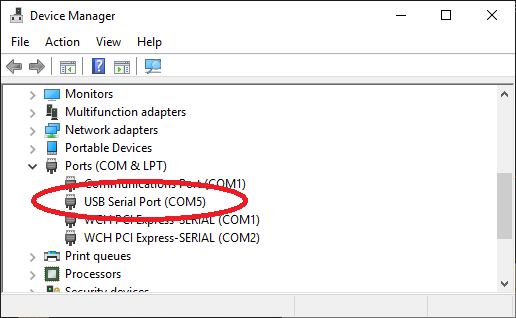
You should then note the port number created by your computer for the virtual serial connection. In Windows this can be done by starting Device Manager and checking the "Ports (COM & LPT)" entry for a new COM port as shown on the right.
Terminal Emulator
You also need a terminal emulator running on your desktop or laptop computer. This is a program that acts like an old fashioned computer terminal where it will display text received from a remote computer and any key presses will be sent to the remote computer over the serial link. The terminal emulator that you use should support VT100 emulation as this is required by the editor built into the PicoMite firmware.
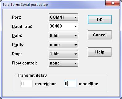
For Windows users it is recommended that you use Tera Term as this has a good VT100 emulator and is known to work with the XModem protocol which you can use to transfer programs to and from the PicoMite. Tera Term can be downloaded from: http://tera-term.en.lo4d.com .
The screen shot on the right shows the setup for Tera Term. Note that the "Port:" setting will vary depending on which USB port your Raspberry Pi Pico was plugged into.
The PicoMite firmware will ignore the baud rate setting so it can be set to any speed (other than 1200 baud which puts the Pico into firmware upgrade mode).
If you are using Tera Term do not set a delay between characters and if you are using Putty set the backspace key to generate the backspace character.
The Console
Once you have identified the virtual serial port and
have connected your terminal emulator to it, you
should be able to press return on your keyboard and
see the MMBasic prompt, which is the greater than
symbol (eg, >).
This is the console and you use it to issue commands to configure MMBasic, load the BASIC program, edit and run it. MMBasic also uses the console to display any error messages.
Windows 7 and 8.1
The USB serial port uses the CDC protocol and the drivers for this are standard in Windows 10 and 11 and will load automatically.
The Raspberry Pi Foundation lists Windows 7 or 8.1 as “unsupported” however you can use a tool like Zadig ( https://zadig.akeo.ie ) to install a generic driver for a “usbser” device and that should allow these computers to connect.
This post describes the process: https://github.com/raspberrypi/pico-feedback/issues/118
Apple Macintosh
The Apple Macintosh (OS X) is somewhat easier as it has the device driver and terminal emulator built in.
First start the application ‘Terminal’ and at the prompt list the connected serial devices by typing in:
ls /dev/tty.*.
The USB to serial converter will be listed as something like /dev/tty.usbmodem12345. While still at the Terminal prompt you can run the terminal emulator at 115200 baud by using the command: screen
/dev/tty.usbmodem12345 115200
By default the function keys will not be correctly defined for use in the PicoMite's built in program editor so you will have to use the control sequences as defined in the chapter Full Screen Editor of this manual. To avoid this you can configure the terminal emulator to generate these codes when the appropriate function keys are pressed.
Documentation for the screen command is here: https://www.systutorials.com/docs/linux/man/1-screen/
Linux
For Linux see these posts:
- https://www.thebackshed.com/forum/ViewTopic.php?TID=14157&PID=175474#175474#175466
- https://www.thebackshed.com/forum/ViewTopic.php?FID=16&TID=16312&LastEntry=Y#213664#213594
Android
For Android devices see this post:
- https://www.thebackshed.com/forum/ViewTopic.php?FID=16&TID=17476&LastEntry=Y#230521#230517
First Steps
Once you have access to the console and the MMBasic prompt there are a few things that you can do to prove that you have a working computer.
All of these commands should be typed at the command prompt (>).
Try a simple calculation:
> PRINT 1/7
0.1428571429
See how much memory you have:
> MEMORY
Program:
0K ( 0%) Program (0 lines)
80K (100%) Free
RAM:
0K ( 0%) 0 Variables
0K ( 0%) General
112K (100%) Free
What is the current time? Note that the PicoMite's clock starts at midnight on power up.
> PRINT TIME$
00:04:01
Set the clock to the current time:
> TIME$ = "10:45"
Check the time again:
> PRINT TIME$
10:45:09
How many milliseconds have elapsed since power up:
> PRINT TIMER
440782 .748
Count to 20:
> FOR a = 1 to 20 : PRINT a; : NEXT a
1 2 3 4 5 6 7 8 9 10 11 12 13 14 15 16 17 18 19 20
A Simple Program
To enter a program, you can use the EDIT command which is described later in this manual. However, for the moment, all that you need to know is that anything that you type will be inserted at the cursor, the arrow keys will move the cursor and backspace will delete the character before the cursor.
To get a quick feel for how the PicoMite works, try this sequence (your terminal emulator must be VT100 compatible):
- At the command prompt type
EDITfollowed by the ENTER key.
The editor should start up and you can enter this line: PRINT "Hello World"
Press the F1 key in your terminal emulator (or CTRL-Q which will do the same thing). This tells the editor to save your program and exit to the command prompt.
At the command prompt type RUN followed by the ENTER key.
You should see the message: Hello World
Congratulations. You have just written and run your first program on the PicoMite. If you type EDIT again you will be back in the editor where you can change or add to your program.
Flashing a LED
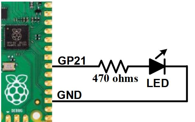
Connect a LED and a 470Ω resistor to pin GP21 (marked on the underside of the board) and a ground pin as shown in the diagram on the right.
Then use the EDIT command to enter the following program:
SETPIN GP21, DOUT
DO
PIN(GP21) = 1
PAUSE 300
PIN(GP21) = 0
PAUSE 300
LOOP
When you have saved and run this program you should be greeted by the LED flashing on and off. It is not a great program but it does illustrate how the PicoMite can interface to the physical world via your programming.
The program itself is simple. The first line sets pin GP21 as an output. Then the program enters a continuous loop where the output of that pin is set high to turn on the LED followed by a short pause (300 milliseconds).
The output is then set to low followed by another pause. The program then repeats the loop.
If you leave it this way, the PicoMite will sit there forever with the LED flashing. If you want to change something (for example, the speed of flashing) you can interrupt the program by typing CTRL-C on the console and then edit it as needed. This is the great benefit of MMBasic, it is very easy to write and change a program.
If you want this program to automatically start running every time power is applied you can use the command:
OPTION AUTORUN ON
To test this you can remove the power and then re-apply it. The PicoMite should start up flashing the LED.
Tutorial on Programming in the BASIC Language
If you are new to the BASIC programming language now would be a good time to turn to Appendix G – Programming in BASIC - A Tutorial at the rear of this manual. This is a comprehensive tutorial on the language which will take you through the fundamentals in an easy to read format with lots of examples.
Programming in BASIC - A Tutorial
The BASIC language was introduced in 1964 by Dartmouth College in the USA as a computer language for teaching programming and accordingly it is easy to use and learn. At the same time, it has proved to be a competent and powerful programming language and as a result it became very popular in the late 70s and early 80s. Even today some large commercial data systems are still written in the BASIC language (primarily Pick Basic).
The BASIC interpreter used in the PicoMite firmware’s is called MMBasic and is a modern version of the BASIC language which loosely emulates the Microsoft BASIC interpreter that was popular years ago.
For a programmer the greatest advantage of BASIC is its ease of use. Some more modern languages such as C and C++ can be truly mind bending but with BASIC you can start with a one line program and get something sensible out of it. MMBasic is also powerful in that you can draw sophisticated graphics, manipulate the external I/O pins to control other devices and communicate with other devices using a range of built-in communications protocols.
Command Prompt
Interaction with MMBasic is done via the console at the command prompt (ie, the greater than symbol
> on the console). On startup MMBasic will issue the command prompt and wait for some
command to be entered. It will also return to the command prompt if your program ends or if it
generated an error message.
When the command prompt is displayed you have a wide range of commands that you can enter and
execute. Typically they would list the program held in memory ( LIST ) or edit it ( EDIT ) or perhaps
set some options (the OPTION command). Most times the command is just RUN which instructs
MMBasic to run the program held in program memory.
Almost any command can be entered at the command prompt and this is often used to test a command
to see how it works. A simple example is the PRINT command (more on this later), which you can
test by entering the following at the command prompt:
PRINT 2 + 2
and not surprisingly MMBasic will print out the number 4 before returning to the command prompt.
This ability to test a command at the command prompt is useful when you are learning to program in BASIC, so it would be worthwhile having a Raspberry Pi Pico loaded with the PicoMite firmware handy for the occasional test while you are working through this tutorial.
Structure of a BASIC Program
A BASIC program starts at the first line and continues until it runs off the end or hits an END
command - at which point MMBasic will display the command prompt > on the console and wait for
something to be entered.
A program consists of a number of statements or commands, each of which will cause the BASIC interpreter to do something (the words statement and command generally mean the same and are used interchangeable in this tutorial).
Normally each statement is on its own line but you can have multiple statements in the one line
separated by the colon character :.
For example:
A = 24.6 : PRINT A
Each line can start with a line number. Line numbers were mandatory in the early BASIC interpreters however modern implementations (such as MMBasic) do not need them. You can still use them if you wish but they have no benefit and generally just clutter up your programs.
This is an example of a program that uses line numbers:
50 A = 24.6
60 PRINT A
A line can also start with a label which can be used as the target for a program jump using the GOTO
command. This will be explained in more detail when we cover the GOTO command but this is an
example (the label name is JmpBack):
JmpBack: A = A + 1
PRINT A
GOTO JmpBack
Comments
A comment is any text that follows the single quote character ('). A comment can be placed anywhere and extends to the end of the line. If MMBasic runs into a comment it will just skip to the end of it (ie, it does not take any action regarding a comment).
Comments should be used to explain non obvious parts of the program and generally inform someone who is not familiar with the program how it works and what it is trying to do. Remember that after only a few months a program that you have written will have faded from your mind and will look strange when you pick it up again. For this reason you will thank yourself later if you use plenty of comments.
The following are some examples of comments:
' calculate the hypotenuse
PRINT SQR(a * a + b * b)
or
INPUT var ' get the temperature
Older BASIC programs used the command REM to start a comment and you can also use that if you
wish but the single quote character is easier to use and more convenient.
The PRINT Command
There are a number of common commands that are fundamental and we will cover them in this tutorial but arguably the most useful is the PRINT command. Its job is simple; to print something on the console. This is mostly used to output data for you to see (like the result of calculations) or provide informative messages.
PRINT is also useful when you are tracing a fault in your program; you can use it to print out the
values of variables and display messages at key stages in the execution of the program.
In its simplest form the command will just print whatever is on its command line. So, for example:
PRINT 54
will display on the console the number 54 followed by a new line.
The data to be printed can be something simple like this or an expression, which means something to be calculated. We will cover expressions in more detail later but as an example the following:
> PRINT 3/21
0.1428571429
>
would calculate the result of three divided by twenty one and display it. Note that the greater than
symbol > is the command prompt produced by MMBasic – you do not type that in.
Other examples of the PRINT command include:
> PRINT "Wonderful World"
Wonderful World
> PRINT (999 + 1) / 5
200
>
You can try these out at the command prompt.
The PRINT command will also work with multiple values at the same time, for example:
> PRINT "The first number is" 20+25 " and the second is" 18/3
The first number is 45 and the second is 6
>
Normally each value is separated by a space character as shown in the previous example but you can also separate values with a comma ,. The comma will cause a tab to be inserted between the two values. In MMBasic tabs in the PRINT command are eight characters apart.
To illustrate tabbing, the following command prints a tabbed list of numbers:
> PRINT 12, 34, 9.4, 1000
12
34
9.4
1000
>
Note that there is a space printed before each number. This space is a place holder for the minus
symbol - in case the value is negative. You can see the difference with the numbers 12 and 9.4 in
this example:
> PRINT -12, 34, -9.4, 1000
-12
34
-9.4
1000
>
The print statement can be terminated with a semicolon (;). This will prevent the PRINT command from moving to a new line when it has printed all the text. For example:
PRINT "This will be";
PRINT " printed on a single line."
Will result in this output:
This will be
printed on a single line.
The message would be look like this without the semicolon at the end of the first line:
This will be
printed on a single line.
Variables
Before we go much further we need to define what a "variable" is as they are fundamental to the operation of the BASIC language (in fact, most programming languages). A variable is simply a place to store an item of data (ie, its "value"). This value can be changed as the program runs which why it is called a "variable".
Variables in MMBasic can be one of three types. The most common is floating point and this is automatically assumed if the type of the variable is not specified. The other two types are integer and string and we will cover them later. A floating point number is an ordinary number which can contain a decimal point. For example 3.45 or -0.023 or 100.00 are all floating point numbers.
A variable can be used to store a number and it can then be used in the same manner as the number itself, in which case it will represent the value of the last number assigned to it.
As a simple example:
A = 3
B = 4
PRINT A + B
will display the number 7. In this case both A and B are variables and MMBasic used their current values in the PRINT statement. MMBasic will automatically create a variable when it first encounters it, so the statement A = 3 both created a floating point variable (the default type) with the name of A and then it assigned the value of 3 to it.
The name of a variable must start with a letter while the remainder of the name can use letters, numbers, the underscore or the full stop (or period) characters. The name can be up to 31 characters long and the case (ie, capitals or not) is not important. Here are some examples:
Total_CountForeColourtemp3countxThisIsAVeryLongVariableNameincrement.value
You can change the value of a variable anywhere in your program by using the assignment command, ie:
variable = expression
For example:
temp3 = 24.6
count = 5
CTemp = (FTemp – 32) * 0.5556
In the last example both CTemp and FTemp are variables and this line converts the value of FTemp
(in degrees Fahrenheit) to degrees Celsius and stores the result in the variable CTemp.
The IF Statement
Making decisions is at the core of most computer programs and in BASIC this is usually done with
the IF statement. This is written almost like an English sentence:
IF condition THEN action
The condition is usually a comparison such as equals, less than, more than, etc.
For example:
IF Temp < 25 THEN PRINT "Cold"
Temp would be a variable holding the current temperature (in ºC) and PRINT "Cold" the action to
be done.
There are a range of tests that you can make:
| Symbol | Meaning |
|---|---|
| = | equals |
| < | less than |
| > | greater than |
| <> | not equal |
| <= | less than or equals |
| >= | greater than or equals |
You can also add an ELSE clause which will be executed if the initial condition tested false:
IF condition THEN true-action ELSE false-action
For example, this will execute different actions when the temperature is under 25 or 25 or more:
IF Temp < 25 THEN PRINT "Cold" ELSE PRINT "Hot"
The previous examples all used single line IF statements but you can also use a multiline IF statement.
They look like this:
IF condition THEN
true-action
true-action
ENDIF
or
IF condition THEN
true-action
true-action
ELSE
false-action
false-action
ENDIF
Unlike the single line IF statement you can have many true actions with each on their own line and
similarly many false actions. Generally the single line IF statement is handy if you have a simple
action that needs to be taken while the multiline version is much easier to understand if the actions are
numerous and more complicated.
An example of a multiline IF statement with more than one action is:
IF Amount < 100 THEN
PRINT "Too low"
PRINT “Minimum value is 100”
ELSE
PRINT "Input accepted"
SaveToSDCard
PRINT "Enter second amount"
ENDIF
Note that in the above example each action is indented to show what part of the IF structure it belongs
to. Indenting is not mandatory but it makes a program much easier to understand for someone who is
not familiar with it and therefore it is highly recommended.
In a multiline IF statement you can make additional tests using the ELSE IF command. This is best
explained by using an example (the temperatures are all in ºC):
IF Temp < 0 THEN
PRINT “Freezing”
ELSE IF Temp < 20 THEN
PRINT “Cold”
ELSE IF Temp < 35 THEN
PRINT “Warm”
ELSE
PRINT “Hot”
ENDIF
The ELSE IF uses the same tests as an ordinary IF (ie, <, <=, etc) but that test will only be made if the
preceding test was false. So, for example, you will only get the message Warm if Temp < 0 failed,
and Temp < 20 failed but Temp < 35 was true. The final ELSE will catch the case where all the
tests were false.
An expression like Temp < 20 is evaluated by MMBasic as either true or false with true having a
value of one and false zero. You can see this if you entered the following at the console:
PRINT 30 > 20
MMBasic will print 1 meaning that the value of the expression is true.
Similarly the following will print 0 meaning that the expression evaluated to false.
PRINT 30 < 20
The IF statement does not really care about what the condition actually is, it just evaluates the condition and if the result is zero it will take that as false and if non zero it will take it as true.
This allows for some handy shortcuts. For example, if BalanceCorrect is a variable that is true
(non zero) when some feature of the program is correct then the following can be used to make a
decision based on that value:
IF BalanceCorrect THEN …do something…
FOR Loops
Another common requirement in programming is repeating a set of actions. For instance, you might
want to step through all seven days in the week and perform the same function for each day. BASIC
provides the FOR loop construct for this type of job and it works like this:
FOR day = 1 TO 7
' Do something based on the value of ‘day’
NEXT day
This starts by creating the variable day and assigning the value of 1 to it. The program will then
execute the following statements until it comes to the NEXT statement. This tells the BASIC
interpreter to increment the value of day, go back to the previous FOR statement and re-execute the
following statements a second time. This will continue looping around until the value of day exceeds
7 and the program will then exit the loop and continue with the statements following the NEXT
statement.
As a simple example, you can print the numbers from one to ten like this:
FOR nbr = 1 TO 10
  PRINT nbr,;
NEXT nbr
Alternatively MMbasic allows you to place multiple statements on a single line by separating them with a colon :.
FOR nbr = 1 TO 10 : PRINT nbr,; : NEXT nbr
The comma at the end of the PRINT statement tells the interpreter to tab to the next tab column after
printing the number and the semicolon will leave the cursor on this line rather than automatically
moving to the next line. As a result, the numbers will be printed in neat columns across the page.
This is what you would see the output:
1 2 3 4 5 6 7 8 9 10
The FOR loop also has a couple of extra tricks up it sleeves. You can change the amount that the
variable is incremented by using the STEP keyword. So, for example, the following will print just the
odd numbers:
FOR nbr = 1 TO 10 STEP 2
PRINT nbr,;
NEXT nbr
The value of the step (or increment value) defaults to one if the STEP keyword is not used but you can
set it to whatever number you want.
When MMBasic is incrementing the variable it will check to see if the variable has exceeded the TO value and, if it has, it will exit from the loop. So, in the above example, the value of nbr will reach nine and it will be printed but on the next loop nbr will be eleven and at that point execution will leave the loop. This test is also applied at the start of the loop. For example, if in the beginning the value of the variable exceeds the TO value, the loop will never be executed, not even once.
By setting the STEP value to a negative number you can use the FOR loop to step down from a high
number to low. In that case the starting number must be greater than the TO number.
For example, the following will print the numbers from 1 to 10 in reverse:
FOR nbr = 10 TO 1 STEP -1
PRINT nbr,;
NEXT nbr
Multiplication Table
To further illustrate how loops work and how useful they can be, the following short program uses two FOR loops to print out the multiplication table that we all learnt at school. The program for this is not complicated:
FOR nbr1 = 1 to 10
FOR nbr2 = 1 to 10
PRINT nbr1 * nbr2,;
NEXT nbr2
PRINT
NEXT nbr1
The output is shown in the following screen grab, which also shows a listing of the program.
You need to work through the logic of this example line by line to understand what it is doing.
Essentially it consists of one loop inside another. The inner loop, which increments the variable nbr2 prints one horizontal line of the table. When this loop has finished it will execute the following PRINT command which has nothing to print - so it will simply output a new line (ie, terminate the line printed by the inner loop).
The program will then execute another iteration of the outer loop by incrementing nbr1 and re-executing the inner loop again. Finally, when the outer loop is exhausted (when nbr1 exceeds 10) the program will reach the end and terminate.
One last point, you can omit the variable name from the NEXT statement and MMBasic will guess which variable you are referring to. However, it is good practice to include the name to make it easier for someone else who is reading the program to understand it. You can also terminate multiple loops using a comma separated list of variables in the NEXT statement. For example:
FOR var1 = 1 TO 5
FOR var2 = 10 to 13
PRINT var1 * var2
NEXT var1, var2
DO Loops
Another method of looping is the DO … LOOP structure which looks like this:
DO WHILE condition
<statement>
<statement>
LOOP
This will start by testing the condition and if it is true the statements will be executed until the LOOP
command is reached, at which point the program will return to DO statement and the condition will be
tested again, and if it is still true the loop will execute again. The condition is the same as in the IF
command (ie, X < Y).
For example, the following will keep printing the word "Hello" on the console for 4 seconds then stop:
Timer = 0
DO WHILE Timer < 4000
PRINT "Hello"
LOOP
Note that Timer is a function within MMBasic which will return the time in milliseconds since the timer was reset. A reset is done by assigning zero to Timer (as done above) or when powering up the PicoMite.
A variation on the DO … LOOP structure is the following:
DO
<statement>
<statement>
LOOP UNTIL condition
In this arrangement the loop is first executed once, the condition is then tested and if the condition is
false, the loop will be repeatedly executed until the condition becomes true. Note that the test in
LOOP UNTIL is the inverse of DO WHILE.
For example, similar to the previous example, the following will also print "Hello" for four seconds:
Timer = 0
DO
PRINT "Hello"
LOOP UNTIL Timer >= 4000
Both forms of the DO … LOOP essentially do the same thing, so you can use whatever structure fits
with the logic that you wish to implement.
Finally, it is possible to have a DO Loop that has no conditions at all.
DO
<statement>
<statement>
LOOP
This construct will continue looping forever and you, as the programmer, will need to provide a way
to explicitly exit the loop (the EXIT DO command will do this).
For example:
Timer = 0
DO
PRINT "Hello"
IF Timer >= 4000 THEN EXIT DO
LOOP
Console Input
As well as printing data for the user to see your programs will also want to get input from the user.
For that to work you need to capture keystrokes from the console and this can be done with the INPUT command. In its simplest form the command is:
INPUT var
This command will print a question mark on the console's screen and wait for a number to be entered
followed by the Enter key. That number will then be assigned to the variable var.
For example, the following program extends the expression for finding the hypotenuse of a triangle by allowing the user to enter the lengths of the other sides from the console.
PRINT "Length of side 1"
INPUT a
PRINT "Length of side 2"
INPUT b
PRINT "Length of the hypotenuse is" SQR(a * a + b * b)
This is a screen capture of a typical session:
The INPUT command can also print your prompt for you, so that you do not need a separate PRINT command. For example, this will work the same as the above program:
INPUT "Length of side 1"; a
INPUT "Length of side 2"; b
PRINT "Length of the hypotenuse is" SQR(a * a + b * b)
Finally, the INPUT command will allow you to input a series of numbers separated by commas with each number being saved in different variables.
For example:
INPUT "Enter the length of the two sides: ", a, b
PRINT "Length of the hypotenuse is" SQR(a * a + b * b)
If the user entered 12,15 the number 12 would be saved in the variable a and 15 in b.
Another method of getting input from the console is the LINE INPUT command. This will get the whole line as typed by the user and allocate it to a string variable. Like the INPUT command you can also specify a prompt. This is a simple example:
LINE INPUT "What is your name? ", s$
PRINT "Hello " s$
We will cover string variables later in this tutorial but for the moment you can think of them as a variable that holds a sequence of characters. If you ran the above program and typed in John when prompted the program would respond with Hello John.
Sometimes you do not want to wait for the user to hit the enter key, you want to get each character as it is typed in. This can be done with the INKEY$ function which will return the value of the character as a string consisting of just one character or an empty string (ie, contains no characters) if nothing has been entered.
Testing for Prime Numbers
The following is a simple program which brings together many of the programming features previously discussed.
DO
  InpErr:
  PRINT
  INPUT "Enter a number: "; a
  IF a < 2 THEN
    PRINT "Number must be 2 or greater"
    GOTO InpErr
  ENDIF
  Divs = 0
  FOR x = 2 TO SQR(a)
    r = a/x
    IF r = FIX(r) THEN Divs = Divs + 1
  NEXT x
  PRINT a " is ";
  IF Divs > 0 THEN PRINT "not ";
  PRINT "a prime number."
LOOP
This will first prompt (on the console) for a number and, when it has been entered, it will test if that number is a prime number or not and display a suitable message.
It starts with a DO-Loop that does not have a condition – so it will continue looping forever. This is what we want. It means that when the user has entered a number, it will report if it is a prime number or not and then loop around and ask for another number. The way that the user can exit the program (if they wanted to) is by typing the break character (normally CTRL-C).
The program then prints a prompt for the user which is terminated with a semicolon character. This
means that the cursor is left at the end of the prompt for the INPUT command which will get the
number and store it in the variable a.
Following this the number is tested. If it is less than 2 an error message will be printed and the program will jump backwards and ask for the number again.
We are now ready to test if the number is a prime number. The program uses a FOR loop to step
through the possible divisors testing if each one can divide evenly into the entered number. Each time
it does the program will increment the variable Divs.
Note that the test is done with the function FIX(r) which simply strips off any digits after the decimal point. So, the condition r = FIX(r) will be true if r is an integer (ie, has no digits after the
decimal point).
Finally, the program will construct the message for the user. The key part is that if the variable Divs
is greater than zero it means that one or more numbers were found that could divide evenly into the
test number. In that case the IF statement inserts the word "not" into the output message.
For example, if the entered number was 21 the user will see this response:
21 is not a prime number.
This is the result of running the program and some of the output:
You can test this program by using the editor (the EDIT command) to enter it.
Using your newly learnt skills you could then have a shot at making it more efficient. For example,
because the program counts how many times a number can be divided into the test number it takes a
lot longer than it should to detect a non prime number. The program would run much more efficiently
if it jumped out of the FOR loop at the first number that divided evenly. You could use the GOTO
command to do this or you could use the command EXIT FOR – that would cause the FOR loop to
terminate immediately.
Other efficiencies include only testing the division with odd numbers (by using an initial test for an
even number then starting the FOR loop at 3 and using STEP 2) or by only using prime numbers for
the test (that would be much more complicated).
Arrays
Arrays are something which you will probably not think of as useful at first glance but when you do need to use them you will find them very handy indeed.
An array is best thought of as a row of letterboxes for a block of units or condos as shown on the right. The letterboxes are all located at the same address and each box represents a unit or condo at that address. You can place a letter in the box for unit one, or unit two, etc.
Similarly an array in BASIC is a single variable with multiple sub units (called elements in BASIC) which are numbered. You
can place data in element one, or element two, etc. In BASIC an array is created by the DIM command, for example:
DIM numarr(300)
This creates an array with the name of numarr containing 301 elements (think of them as letterboxes) ranging from 0 to 300. By default an array will start from zero so this is why there is an extra element making the total 301. To specify a specific element in the array (ie, a specific letterbox) you use an index which is simply the number of the array element that you wish to access.
For example, if you want to set element number 100 in this array to (say) the number 876, you would do it this way:
numarr(100) = 876
Normally the index to an array is not a constant number as in this example (ie, 100) but a variable which can be changed to access different array elements.
As an example of how you might use an array, consider the case where you would like to record the maximum temperature for each day of the year and, at the end of the year, calculate the overall average. You could use ordinary variables to record the temperature for each day but you would need 365 of them and that would make your program quite unwieldy. Instead, you could define an array to hold the values like this:
DIM days(365)
Every day you would need to save the temperature in the correct location in the array. If the number of the day in the year was held in the variable doy and the maximum temperature was held in the variable maxtemp you would save the reading like this:
days(doy) = maxtemp
At the end of the year it would be simple to calculate the average for the year.
For example:
total = 0
FOR i = 1 to 365
total = total + days(i)
NEXT i
PRINT "Average is:" total / 365
This is much easier than adding up and averaging 365 individual variables.
The above array was single dimensioned but you can have multiple dimensions. Reverting to our analogy of letterboxes, an array with two dimensions could be thought of as a block of flats with multiple floors. A block could have a row of four letter boxes for level one, another row of four boxes for level two, and so on. To place a letter in a letterbox you need to specify the floor number and the unit number on that floor.
In BASIC such an array is specified using two indices separated by a comma. For example:
LetterBox(floor, unit)
As a practical example, assume that you needed to record the maximum temperature for each day over five years. To do this you could dimension the array as follows:
DIM days(365, 5)
The first index is the day in the year and the second is a number representing the year. If you wanted to set day 100 in year 3 to 24 degrees you would do it like this:
days(100, 3) = 24
In MMBasic for the PicoMite firmware, you can have up to six dimensions with the RP2040 processor or five dimensions with the RP2350 processor. The size of an array is limited only by the amount of free RAM that is available.
Integers
So far all the numbers and variables that we have been using have been floating point. As explained before, floating point is handy because it will track digits after the decimal point and when you use division it will return a sensible result. So, if you just want to get things done and are not concerned with the details you should stick to floating point.
However, the limitation of floating point is that it stores numbers as an approximation with an accuracy of 14 digits in the PicoMite firmware . Most times this characteristic of floating point numbers is not a problem but there are some cases where you need to accurately store larger numbers.
As an example, let us say that you want to manipulate time accurately down to the microsecond so
that you can compare two different date/times to work out which one is earlier. The easy way to do
this is to convert the date/time to the number of microseconds since some date (say 1st Jan in year
zero) - then finding the earliest of the two is just a matter of using an arithmetic compare in an IF
statement.
The problem is that the number of microseconds since that date will exceed the accuracy range of floating point variables and this is where integer variables come in. An integer variable can accurately hold very large numbers up to nine million million million (or ±9223372036854775807 to be precise).
The downside of using an integer is that it cannot store fractions (ie, numbers after the decimal point).
Any calculation that produces a fractional result will be rounded up or down to the nearest whole number when assigned to an integer. However this characteristic can be handy when dealing with money – for example, you don’t want to send someone a bill for $100.13333333333.
It is easy to create an integer variable, just add the percent symbol (%) as a suffix to a variable name.
For example, sec% is an integer variable. Within a program you can mix integers and floating point and MMBasic will make the necessary conversions but if you want to maintain the full accuracy of integers you should avoid mixing the two.
Just like floating point you can have arrays of integers, all you need to do is add the percent character as a suffix to the array name. For example: days%(365, 5).
Beginners often get confused as to when they should use floating point or integers and the answer is simple… always use floating point unless you need an extremely high level of accuracy. This does not happen often but when you need them you will find that integers are quite useful.
Scientific Notation
Before we finish discussing data types we need to cover off the subject of floating point numbers and scientific notation.
Most numbers can be written normally, for example 11 or 24.5, but very large or small numbers are more difficult. For example, it has been estimated that the number of grains of sand on planet Earth is 7500000000000000000. The problem with this number is that you can easily lose track of how many zeros there are in the number and consequently it is difficult to compare this with a similar sized number.
A scientist would write this number as 7.5 x 10¹⁸ which is called scientific notation and is much easier to comprehend.
MMBasic will automatically shift to scientific notation when dealing with very large or small floating
point numbers. For example, if the above number was stored in a floating point variable the PRINT
command would display it as 7.5E+18 (this is BASIC’s way of representing 7.5 x 10¹⁸). As another
example, the number 0.0000000456 would display as 4.56E-8 which is the same as 4.56 x 10⁻⁸.
You can also use scientific notation when entering constant numbers in MMBasic. For example:
SandGrains = 7.5E+18
MMBasic only uses scientific notation for displaying floating point numbers (not integers). For instance, if you assigned the number of grains of sand to an integer variable it would print out as a normal number (with lots of zeros).
String
Strings are another variable type (like floating point and integers). Strings are used to hold a sequence of characters.
For example, in the command:
PRINT "Hello"
The string "Hello" is a string constant. Note that a constant is something that does not change (as against a variable, which can) and that string constants are always surrounded by double quotes.
String variables names use the dollar symbol ($) as a suffix to identify them as a string instead of a normal floating point variable and you can use ordinary assignment to set their value. The following are examples (note that the second example uses an array of strings):
Car$ = "Holden"
Country$(12) = "India"
Name$ = "Fred"
You can also join strings using the plus operator:
Word1$ = "Hello"
Word2$ = "World"
Greeting$ = Word1$ + " " + Word2$
In which case the value of Greeting$ will be "Hello World".
Strings can also be compared using operators such as = (equals), <> (not equals), < (less than), etc.
For example:
IF Car$ = "Holden" THEN PRINT "Was an Aussie made car"
The comparison is made using the full ASCII character set so a space will come before a printable
character. Also the comparison is case sensitive so 'holden' will not equal "Holden". Using the
function UCASE() to convert the string to upper case you can then have a case insensitive
comparison. For example:
IF UCASE$(Car$) = "HOLDEN" THEN PRINT "Was an Aussie made car"
Long Strings
The maximum length of a standard string is 255, longer character sequences can be declared as long strings.
Arrays of Strings
You can have arrays of strings but you need to be careful when you declare them as you can rapidly run out of RAM (general memory used for storing variables, etc). This is because MMBasic will by default allocate 255 bytes of RAM for each element of the array.
For example, a string array with 100 elements will by default use 25K of RAM.
To alleviate this you can use the LENGTH qualifier to limit the maximum size of each element. For instance, if you know that the maximum length of any string that will be stored in the array will be less than 20 characters you can use the following declaration to allocate just 20 bytes for each element:
DIM MyArray$(100) LENGTH 20
The resultant array will only use 2K of RAM.
Note that sometimes people think that by using the LENGTH qualifier when declaring a normal (non
array) string variable they will save some RAM. This is not correct; they always occupy 256 bytes.
Manipulating Strings
String handling is one of MMBasic's strengths and using a few simple functions you can pull apart and generally manipulate strings. The basic string functions are:
| Command | Description |
|---|---|
LEFT$(string$, nbr ) | Returns a substring of string$ with nbr of characters from the left (beginning) of the string. |
RIGHT$(string$, nbr ) | Same as the above but return nbr of characters from the right (end) of the string. |
MID$(string$, pos, nbr ) | Returns a substring of string$ with nbr of characters starting from the character pos in the string (ie, the middle of the string). |
For example if S$ = "This is a string"
- then:
R$ = LEFT$(S$, 7)would result in the value of R$ being set to: "This is" - and:
R$ = RIGHT$(S$, 8)would result in the value of R$ being set to: "a string" - finally:
R$ = MID$(S$, 6, 2)would result in the value of R$ being set to: "is"
Note that in MID$() the first character position in a string is number 1, the second is number 2 and so
on. So, counting the first character as one, the sixth position is the start of the word "is".
Searching Strings
Another useful function is: INSTR(string$, pattern$ ) , which returns a number representing the position at which pattern$ occurs in string$.
This can be used to search for a string inside another string. The number returned is the position of
the substring inside the main string. Like with MID$() the start of the string is position 1.
For example if S$ = "This is a string" Then: pos = INSTR(S$, " ") would result in pos being set to the position of the first space in S$ (ie, 5).
INSTR() can be combined with other functions so this would return the first word in S$:
R$ = LEFT$(S$, INSTR(S$, " ") - 1)
Searching from a starting point
There is also an extended version of INSTR():
INSTR(pos, string$, pattern$ )
Returns a number representing the position at which pattern$ occurs in string$ when starting the search at the character position pos.
So we can find the second word in S$ using the following:
pos = INSTR(S$, " ")
R$ = LEFT$(S$, INSTR(pos + 1, S$, " ") - 1)
This last example is rather complicated so it might be worth working through it in detail so that you can understand how it works.
Note that INSTR() will return the number zero if the sub string is not found and that any string
function will throw an error (and halt the program) if that is used as a character position. So, in a
practical program you would first check for zero being returned by INSTR() before using that value.
For example:
pos = INSTR(S$, " ")
if pos > 0 THEN R$ = LEFT$(S$, INSTR(pos + 1, S$, " ") - 1)
Searching using Regular expressions
DIM Command
We have used the DIM command before for defining arrays but it can also be used to create ordinary
variables. For example, you can simultaneously create four string variables like this:
DIM STRING Car, Name, Street, City
Note that because these variables have been defined as strings using the DIM command we do not
need the $ suffix, the definition alone is enough for MMBasic to identify their type. Similarly, when
you use these variables in an expression you do not need the type suffix: For example:
City = "Sydney"
You can also use the keyword INTEGER to define a number of integer variables and FLOAT to do
the same for floating point variables. This type of notation can similarly be used to define arrays.
For example:
DIM INTEGER seconds(200)
Another method of defining the variables type is to use the keyword AS. For example:
DIM Car AS STRING, Name AS STRING, Street AS STRING
This is the method used by Microsoft (MMBasic tries to maintain Microsoft compatibility) and it is useful if the variables have different types. For example:
DIM Car AS STRING, Age AS INTEGER, Value AS FLOAT
You can use any of these methods of defining a variable's type, they all act the same.
Require explicit definitions
The advantage of defining variables using the DIM command is that they are clearly defined
(preferably at the start of the program) and their type (float, integer or string) is not subject to
misinterpretation.
You can strengthen this by using the following commands at the very top of your program:
OPTION EXPLICIT
OPTION DEFAULT NONE
The first specifies to MMBasic that all variables must be explicitly defined using DIM before they can
be used. The second specifies that the type of all variables must be specified when they are created.
Why are these two commands important?
The first can help avoid a common programming error which is where you accidently misspell a variable's name. For example, your program might have the current temperature saved in a variable called Temp but at one point you accidently misspell it as Tmp. This will cause MMBasic to automatically create a variable called Tmp and set its value to zero.
This is obviously not what you want and it will introduce a subtle error which could be hard to find,
even if you were aware that something was not right. On the other hand, if you used the OPTION EXPLICIT command at the start of your program MMBasic would refuse to automatically create the
variable and instead would display an error thereby saving you from a probable headache.
The command OPTION DEFAULT NONE further helps because it tells MMBasic that the
programmer must specifically specify the type of every variable when they are declared. It is easy to
forget to specify the type and allowing MMBasic to automatically assume the type can lead to
unexpected consequences.
For small, quick and dirty programs, it is fine to allow MMBasic to automatically create variables but
in larger programs you should always disable this feature with OPTION EXPLICIT and strengthen it
with OPTION DEFAULT NONE .
When a variable is created it is set to zero for float and integers and an empty string (ie, contains no
characters) for a string variable. You can set its initial value to something else when it is created using
DIM .
For example:
DIM FLOAT nbr = 12.56
DIM STRING Car = "Ford", City = "Perth"
You can also initialise arrays by placing the initialising values inside brackets like this:
DIM s$(2) = ("zero", "one", "two")
Note that because arrays start from zero by default this array actually has three elements with the index numbers of 0, 1 and 2. This is why we needed three string constants to initialise it.
Constants
A common requirement in programming is to define an identifier that represents a value without the risk of the value being accidently changed - which can happen if variables were used for this purpose.
These are called constants and they can represent I/O pin numbers, signal limits, mathematical constants and so on.
You can create a constant using the CONST command. This defines an identifier that acts like a
variable but is set to a value that cannot be changed.
For example, if you wanted to check the voltage of a battery connected to pin 31 you could define the relevant values thus:
CONST BatteryVoltagePin = 31
CONST BatteryMinimum = 1.5
These constants can then be used in the program where they make more sense to the casual reader than simple numbers. For example:
SETPIN BatteryVoltagePin, AIN
IF PIN(BatteryVoltagePin) < BatteryMinimum THEN SoundAlarm
It is good programming practice to use constants for any fixed number that represents an important value. Normally they are defined at the start of a program where they are easy to see and conveniently located for another programmer to adjust (if necessary).
Subroutines
A subroutine is a block of programming code which is self contained (like a module) and can be called from anywhere within your program. To your program it looks like a built in MMBasic command and can be used the same. For example, assume that you need a command that would signal an error by printing a message on the console. You could define the subroutine like this:
SUB ErrMsg
PRINT "Error detected"
END SUB
With this subroutine embedded in your program all you have to do is use the command ErrMsg whenever you want to display the message. For example:
IF A < B THEN ErrMsg
The definition of a subroutine can be anywhere in the program but typically it is at the end. If MMBasic runs into the definition while running your program it will simply skip over it.
The above example is fine enough but it would be better if a more useful message could be displayed, one that could be customised every time the subroutine was called. This can be done by passing a string to the subroutine as an argument (sometimes called a parameter).
In this case the definition of the subroutine would look like this:
SUB ErrMsg Msg$
PRINT "Error: " + Msg$
END SUB
Then, when you call the subroutine, you can supply the string to be printed on the command line of the subroutine.
For example:
IF A < B THEN ErrMsg "Number too small"
When the subroutine is called like this the message "Error: Number too small" will be
printed on the console. Inside the subroutine Msg$ will have the value of "Number too small" when
called like this and it will be concatenated in the PRINT statement to make the full error message.
A subroutine can have any number of arguments which can be float, integer or string with each argument separated by a comma.
Within the subroutine the arguments act like ordinary variables but they exist only within the subroutine and will vanish when the subroutine ends. You can have variables with the same name in the main program and they will be hidden within the subroutine and be different from arguments defined for the subroutine.
The type of the argument to be supplied can be specified with a type suffix (ie, $, % or ! for string, integer and float). For example, in the following the first argument must be a string and the second an integer:
SUB MySub Msg$, Nbr%
…
END SUB
MMBasic will convert the supplied values if it can, so if your program supplied a floating point value as the second argument MMBasic will convert it to an integer. If MMBasic cannot convert the value it will display an error and return to the command prompt. For example, if you supplied a string for the second argument your program will stop with an error.
You do not have to use the type suffixes, you can instead define the type of the arguments using the
AS keyword similar to the way it is used in the DIM command.
For example, the following is identical to the above example:
SUB MySub Msg AS STRING, Nbr AS INTEGER
…
END SUB
Of course, if you used only one variable type throughout the program and used OPTION DEFAULT
to set that type you could ignore the question of variable types completely.
When a subroutine is called with an argument that is a variable (ie, not a constant or expression) MMBasic will create a corresponding variable within the subroutine that points back to this variable.
Any changes to the variable representing the argument inside the subroutine will also change the variable used in the call. This is called passing arguments by reference.
This is best explained by example:
DIM MyNumber = 5      ‘ set the variable to 5
CalcSquare MyNumber   ‘ the subroutine will square its value
PRINT MyNumber
END
SUB CalcSquare nbr    ‘ this will print the number 25
nbr = nbr * nbr       ‘ square the argument and pass it back
END SUB
The subroutine CalcSquare will take its argument, square it and write it back to the variable
representing the argument (nbr). Because the subroutine was called with a variable (MyNumber) the
variable nbr will point back to MyNumber and any change to nbr will also change MyNumber
accordingly. As a result the PRINT statement will output 25.
Passing arguments by reference is handy because it allows a subroutine to pass values back to the
code that called it. However, it could lead to trouble if a subroutine used the variable representing an
argument as a general purpose variable and changed its value. Then, if it were called with a variable as
an argument, that variable would be inadvertently changed. To avoid this, you should prefix its
definition with the keyword BYVAL . This instructs MMBasic to always use the value of the
argument, even if it is a variable, and to never point back to the variable used in the call.
When you call a subroutine you can omit some (or all) of the parameters and they will take the value of zero (for floats or integers) or an empty string. This is handy as your subroutine can tell if a parameter is missing and act accordingly.
For example, here is our subroutine to generate an error message but this version can be used without specifying an error message as a parameter:
SUB ErrMsg Msg$
IF Msg$ = "" THEN
PRINT "Error detected"
ELSE
PRINT "Error: " + Msg$
ENDIF
END SUB
Within a subroutine you can use most features of MMBasic including calling other subroutines,
IF … THEN commands, FOR…NEXT loops and so on. However, one thing that you cannot do is
jump out of a subroutine using GOTO (if you do the result will be undefined and may cause your hair
to turn grey).
Normally the subroutine will exit when the END SUB command is reached but you can also terminate
the subroutine early by using the EXIT SUB command.
Functions
Functions are similar to subroutines with the main difference being that a function is used to return a value in an expression. For example, if you wanted a function to convert a temperature from degrees Celsius to Fahrenheit you could define:
FUNCTION Fahrenheit(C)
Fahrenheit = C * 1.8 + 32
END FUNCTION
Then you could use it in an expression:
Input "Enter a temperature in Celsius: ", t
PRINT "That is the same as" Fahrenheit(t) "F"
Or as another example:
IF Fahrenheit(temp) <= 32 THEN PRINT "Freezing"
You could also define the reverse:
FUNCTION Celsius(F)
Celsius = (F - 32) * 0.5556
END FUNCTION
As you can see, the function name is used as an ordinary local variable inside the subroutine. It is only when the function returns that the value is made available to the expression that called it.
The rules for the argument list in a function are similar to subroutines. The only difference is that parentheses are always required around the argument list when you are calling a function, even if there are no arguments (parentheses are optional when calling a subroutine).
To return a value from the function you assign a value to the function's name within the function. If the function's name is terminated with a type suffix (ie, $, a % or a !) the function will return that type
(string, integer or float), otherwise it will return whatever the OPTION DEFAULT is set to. For
example, the following function will return a string:
FUNCTION LVal$(nbr)
IF nbr = 0 THEN LVal$ = "False" ELSE LVal$ = "True"
END FUNCTION
You can explicitly specify the type of the function by using the AS keyword and then you do not need
to use a type suffix (similar to defining a variable using DIM ).
This is the above example rewritten to take advantage of this feature:
FUNCTION LVal(nbr) AS STRING
IF nbr = 0 THEN LVal = "False" ELSE LVal = "True"
END FUNCTION
In this case the type returned by the function LVal will be a string.
As for subroutines you can use most features of MMBasic within functions. This includes
FOR…NEXT loops, calling other functions and subroutines, etc. Also, the function will return to the
expression that called it when the END FUNCTION command is reached but you can also return early
by using the EXIT FUNCTION command.
LOCAL
STATIC
Calculate Days
We have covered a lot of programming commands and techniques so far in this tutorial and before we finish it would be worth giving an example of how they work together. The following is an example that uses many features of the BASIC language to calculate the number of days between two dates:
' Example program to calculate the number of days between two dates
OPTION EXPLICIT
OPTION DEFAULT NONE
DIM STRING s
DIM FLOAT d1, d2
DO
' main program loop
PRINT : PRINT "Enter the date as dd mmm yyyy"
PRINT " First date";
INPUT s
d1 = GetDays(s)
IF d1 = 0 THEN PRINT "Invalid date!" : CONTINUE DO
PRINT "Second date";
INPUT s
d2 = GetDays(s)
IF d2 = 0 THEN PRINT "Invalid date!" : CONTINUE DO
PRINT "Difference is" ABS(d2 - d1) " days"
LOOP
' Calculate the number of days since 1/1/1900
FUNCTION GetDays(d$) AS FLOAT
LOCAL STRING Month(11) =
("jan","feb","mar","apr","may","jun","jul","aug","sep","oct","nov","dec")
LOCAL FLOAT Days(11) = (0,31,59,90,120,151,181,212,243,273,304,334)
LOCAL FLOAT day, mth, yr, s1, s2
' Find the separating space character within a date
s1 = INSTR(d$, " ")
IF s1 = 0 THEN EXIT FUNCTION
s2 = INSTR(s1 + 1, d$, " ")
IF s2 = 0 THEN EXIT FUNCTION
' Get the day, month and year as numbers
day = VAL(MID$(d$, 1, s2 - 1)) - 1
IF day < 0 OR day > 30 THEN EXIT FUNCTION
FOR mth = 0 TO 11
IF LCASE$(MID$(d$, s1 + 1, 3)) = Month(mth) THEN EXIT FOR
NEXT mth
IF mth > 11 THEN EXIT FUNCTION
yr = VAL(MID$(d$, s2 + 1)) - 1900
IF yr < 1 OR yr >= 200 THEN EXIT FUNCTION
' Calculate the number of days including adjustment for leap years
GetDays = (yr * 365) + FIX((yr - 1) / 4)
IF yr MOD 4 = 0 AND mth >= 2 THEN GetDays = GetDays + 1
GetDays = GetDays + Days(mth) + day
END FUNCTION
Note that the line starting LOCAL STRING Month(11) has been wrapped around because of the limited page width – it is one line as follows:
LOCAL STRING Month(11) = ("jan","feb","mar","apr","may","jun","jul","aug","sep","oct","nov","dec")
This program works by getting two dates from the user at the console and then converting them to integers representing the number of days since 1900. With these two numbers a simple subtraction will give the number of days between them.
When this program is run it will ask for the two dates to be entered and you need to use the form of: dd mmm yyyy.
This screen capture shows what the running program will look like.
The main feature of the program is the defined function GetDays() which takes a string entered at the console, splits it into its day, month and year components then calculates the number of days since 1st January 1900.
This function is called twice, once for the first date and then again for the second date. It is then just a matter of subtracting one date (in days) from the other to get the difference in days.
We will not go into the detail of how the calculations are made (ie, handling leap years) as that can be left as an exercise for the reader. However, it is appropriate to point out some features of MMBasic that are used by the program.
It demonstrates how local variables can be used and how they can be initialised. In the function GetDays() two arrays are declared and initialised at the same time. These are just a convenient method of looking up the names of the months and the cumulative number of days for each month.
Later in the function (the FOR loop) you can see how they make dealing with twelve different months quite efficient.
Another feature highlighted by this program is the string handling features of MMBasic. The INSTR() function is used to locate the two space characters in the date string and then later the MID$() function uses these to extract the day, month and year components of the date. The VAL() function is used to turn a string of digits (like the year) into a number that can be stored in a numeric variable.
Note that the value of a function is initialised to zero every time the function is called and unless it is set to some value it will return a zero value. This makes error handling easy because we can just exit the function if an error is discovered. It is then the responsibility of the calling program code to check for a return value of zero which signifies an error.
This program illustrates one of the benefits of using subroutines and functions which is that when written and fully tested they can be treated as a trusted "black box" that does not have to be opened.
For this reason functions like this should be the properly tested and then, if possible, left untouched (in case you add some error).
There are a few features of this program that we have not covered before. The first is the MOD operator which will calculate the remainder of dividing one number into another. For example, if you divided 4 into 15 you would have a remainder of 3 which is exactly what the expression 15 MOD 4 will return. The ABS() function is also new and will return its argument as a positive number (eg, ABS(-15) will return +15 as will ABS(15)).
The EXIT FOR command will exit a FOR loop even though it has not reached the end of its looping, EXIT FUNCTION will immediately exit a function even though execution has not reached the end of the function and CONTINUE DO will immediately cause the program to jump to the end of a DO loop and execute it again.
Why would this program be useful? Well some people like to count their age in days, that way every day is a birthday! You can calculate your age in days, just enter the date that you were born and today's date. That is not particularly useful but the program itself is valuable as it demonstrates many of the characteristics of programming in MMBasic. So, work your way through the program and review each section until you understand it – it should be a rewarding experience.
Command Prompt
Interaction with MMBasic is done via the console at the command prompt (ie, the greater than symbol
> on the console). On startup MMBasic will issue the command prompt and wait for some
command to be entered. It will also return to the command prompt if your program ends or if it
generated an error message.
When the command prompt is displayed you have a wide range of commands that you can enter and
execute. Typically they would list the program held in memory ( LIST ) or edit it ( EDIT ) or perhaps
set some options (the OPTION command). Most times the command is just RUN which instructs
MMBasic to run the program held in program memory.
Almost any command can be entered at the command prompt and this is often used to test a command
to see how it works. A simple example is the PRINT command (more on this later), which you can
test by entering the following at the command prompt:
PRINT 2 + 2
and not surprisingly MMBasic will print out the number 4 before returning to the command prompt.
This ability to test a command at the command prompt is useful when you are learning to program in BASIC, so it would be worthwhile having a Raspberry Pi Pico loaded with the PicoMite firmware handy for the occasional test while you are working through this tutorial.
Structure of a BASIC Program
A BASIC program starts at the first line and continues until it runs off the end or hits an END
command - at which point MMBasic will display the command prompt > on the console and wait for
something to be entered.
A program consists of a number of statements or commands, each of which will cause the BASIC interpreter to do something (the words statement and command generally mean the same and are used interchangeable in this tutorial).
Normally each statement is on its own line but you can have multiple statements in the one line
separated by the colon character :.
For example:
A = 24.6 : PRINT A
Each line can start with a line number. Line numbers were mandatory in the early BASIC interpreters however modern implementations (such as MMBasic) do not need them. You can still use them if you wish but they have no benefit and generally just clutter up your programs.
This is an example of a program that uses line numbers:
50 A = 24.6
60 PRINT A
A line can also start with a label which can be used as the target for a program jump using the GOTO
command. This will be explained in more detail when we cover the GOTO command but this is an
example (the label name is JmpBack):
JmpBack: A = A + 1
PRINT A
GOTO JmpBack
Comments
A comment is any text that follows the single quote character ('). A comment can be placed anywhere and extends to the end of the line. If MMBasic runs into a comment it will just skip to the end of it (ie, it does not take any action regarding a comment).
Comments should be used to explain non obvious parts of the program and generally inform someone who is not familiar with the program how it works and what it is trying to do. Remember that after only a few months a program that you have written will have faded from your mind and will look strange when you pick it up again. For this reason you will thank yourself later if you use plenty of comments.
The following are some examples of comments:
' calculate the hypotenuse
PRINT SQR(a * a + b * b)
or
INPUT var ' get the temperature
Older BASIC programs used the command REM to start a comment and you can also use that if you
wish but the single quote character is easier to use and more convenient.
The PRINT Command
There are a number of common commands that are fundamental and we will cover them in this tutorial but arguably the most useful is the PRINT command. Its job is simple; to print something on the console. This is mostly used to output data for you to see (like the result of calculations) or provide informative messages.
PRINT is also useful when you are tracing a fault in your program; you can use it to print out the
values of variables and display messages at key stages in the execution of the program.
In its simplest form the command will just print whatever is on its command line. So, for example:
PRINT 54
will display on the console the number 54 followed by a new line.
The data to be printed can be something simple like this or an expression, which means something to be calculated. We will cover expressions in more detail later but as an example the following:
> PRINT 3/21
0.1428571429
>
would calculate the result of three divided by twenty one and display it. Note that the greater than
symbol > is the command prompt produced by MMBasic – you do not type that in.
Other examples of the PRINT command include:
> PRINT "Wonderful World"
Wonderful World
> PRINT (999 + 1) / 5
200
>
You can try these out at the command prompt.
The PRINT command will also work with multiple values at the same time, for example:
> PRINT "The first number is" 20+25 " and the second is" 18/3
The first number is 45 and the second is 6
>
Normally each value is separated by a space character as shown in the previous example but you can also separate values with a comma ,. The comma will cause a tab to be inserted between the two values. In MMBasic tabs in the PRINT command are eight characters apart.
To illustrate tabbing, the following command prints a tabbed list of numbers:
> PRINT 12, 34, 9.4, 1000
12
34
9.4
1000
>
Note that there is a space printed before each number. This space is a place holder for the minus
symbol - in case the value is negative. You can see the difference with the numbers 12 and 9.4 in
this example:
> PRINT -12, 34, -9.4, 1000
-12
34
-9.4
1000
>
The print statement can be terminated with a semicolon (;). This will prevent the PRINT command from moving to a new line when it has printed all the text. For example:
PRINT "This will be";
PRINT " printed on a single line."
Will result in this output:
This will be
printed on a single line.
The message would be look like this without the semicolon at the end of the first line:
This will be
printed on a single line.
Variables
Before we go much further we need to define what a "variable" is as they are fundamental to the operation of the BASIC language (in fact, most programming languages). A variable is simply a place to store an item of data (ie, its "value"). This value can be changed as the program runs which why it is called a "variable".
Variables in MMBasic can be one of three types. The most common is floating point and this is automatically assumed if the type of the variable is not specified. The other two types are integer and string and we will cover them later. A floating point number is an ordinary number which can contain a decimal point. For example 3.45 or -0.023 or 100.00 are all floating point numbers.
A variable can be used to store a number and it can then be used in the same manner as the number itself, in which case it will represent the value of the last number assigned to it.
As a simple example:
A = 3
B = 4
PRINT A + B
will display the number 7. In this case both A and B are variables and MMBasic used their current values in the PRINT statement. MMBasic will automatically create a variable when it first encounters it, so the statement A = 3 both created a floating point variable (the default type) with the name of A and then it assigned the value of 3 to it.
The name of a variable must start with a letter while the remainder of the name can use letters, numbers, the underscore or the full stop (or period) characters. The name can be up to 31 characters long and the case (ie, capitals or not) is not important. Here are some examples:
Total_CountForeColourtemp3countxThisIsAVeryLongVariableNameincrement.value
You can change the value of a variable anywhere in your program by using the assignment command, ie:
variable = expression
For example:
temp3 = 24.6
count = 5
CTemp = (FTemp – 32) * 0.5556
In the last example both CTemp and FTemp are variables and this line converts the value of FTemp
(in degrees Fahrenheit) to degrees Celsius and stores the result in the variable CTemp.
Expressions
We have met the term ‘expression’ before in this tutorial and in programming it has a specific meaning. It is a formula which can be resolved by the BASIC interpreter to a single number or value.
MMBasic will evaluate numeric expressions using the same rules that we learnt at school. For example, multiplication and division are performed first followed by addition and subtraction. These are called the rules of precedence and are fully described previously in this manual (see the chapter Expressions and Operators).
This means that MMBasic will resolve 2 + 3 * 6 by first multiplying 3 by 6 giving 18 then adding 2
resulting in a final value of 20. Similarly, both 5 * 4 and 10 + 4 * 3 – 2 will also resolve to 20.
If you want to force the interpreter to evaluate parts of the expression first you can surround that part
of the expression with brackets. For example, (10 + 4) * (3 – 2) will resolve to 14 not 20 as would
have been the case if the brackets were not used. Using brackets does not appreciably slow down the
program so you should use them liberally if there is a chance that MMBasic will misinterpret your
intention.
As pointed out earlier, you can use variables in an expression exactly the same as straight numbers.
For example, this will increment the value of the variable temp by one:
temp = temp + 1
You can also use functions in expressions. These are special operations provided by MMBasic, for example to calculate trigonometric values.
An example of using a function is the following which will print the length of the hypotenuse of a
right angled triangle. This uses the SQR() function which returns the square root of a number (a and
b are variables holding the lengths of the other sides):
PRINT SQR(a * a + b * b)
MMBasic will first evaluate this expression by multiplying a by a, then multiplying b by b, then
adding the results together. The resulting number is then passed to the SQR() function which will
calculate the square root of that number (ie, the hypotenuse) and return it for the PRINT command to
display.
Some other mathematical functions provided by MMBasic include:
SIN(r)– the sine of rCOS(r)– the cosine of rTAN(r)– the tangent of r
There are many more functions available to you and they are all listed earlier in this manual.
Note that in the above trigonometric functions the value passed to the function (ie, 'r') is the angle in radians. In MMBasic you can use the function RAD(d) to convert an angle from degrees to radians ('d' is the angle in degrees).
Another feature of most programming languages (including BASIC) is that you can nest function calls within each other. For example, given the angle in degrees (ie, 'd') the sine of that angle can be found with this expression:
PRINT SIN(RAD(d))
In this case MMBasic will first take the value of d and convert it to radians using the RAD() function.
The output of this function then becomes the input to the SIN() function.
Console Input
As well as printing data for the user to see your programs will also want to get input from the user.
For that to work you need to capture keystrokes from the console and this can be done with the INPUT command. In its simplest form the command is:
INPUT var
This command will print a question mark on the console's screen and wait for a number to be entered
followed by the Enter key. That number will then be assigned to the variable var.
For example, the following program extends the expression for finding the hypotenuse of a triangle by allowing the user to enter the lengths of the other sides from the console.
PRINT "Length of side 1"
INPUT a
PRINT "Length of side 2"
INPUT b
PRINT "Length of the hypotenuse is" SQR(a * a + b * b)
This is a screen capture of a typical session:
The INPUT command can also print your prompt for you, so that you do not need a separate PRINT command. For example, this will work the same as the above program:
INPUT "Length of side 1"; a
INPUT "Length of side 2"; b
PRINT "Length of the hypotenuse is" SQR(a * a + b * b)
Finally, the INPUT command will allow you to input a series of numbers separated by commas with each number being saved in different variables.
For example:
INPUT "Enter the length of the two sides: ", a, b
PRINT "Length of the hypotenuse is" SQR(a * a + b * b)
If the user entered 12,15 the number 12 would be saved in the variable a and 15 in b.
Another method of getting input from the console is the LINE INPUT command. This will get the whole line as typed by the user and allocate it to a string variable. Like the INPUT command you can also specify a prompt. This is a simple example:
LINE INPUT "What is your name? ", s$
PRINT "Hello " s$
We will cover string variables later in this tutorial but for the moment you can think of them as a variable that holds a sequence of characters. If you ran the above program and typed in John when prompted the program would respond with Hello John.
Sometimes you do not want to wait for the user to hit the enter key, you want to get each character as it is typed in. This can be done with the INKEY$ function which will return the value of the character as a string consisting of just one character or an empty string (ie, contains no characters) if nothing has been entered.
The IF Statement
Making decisions is at the core of most computer programs and in BASIC this is usually done with
the IF statement. This is written almost like an English sentence:
IF condition THEN action
The condition is usually a comparison such as equals, less than, more than, etc.
For example:
IF Temp < 25 THEN PRINT "Cold"
Temp would be a variable holding the current temperature (in ºC) and PRINT "Cold" the action to
be done.
There are a range of tests that you can make:
| Symbol | Meaning |
|---|---|
| = | equals |
| < | less than |
| > | greater than |
| <> | not equal |
| <= | less than or equals |
| >= | greater than or equals |
You can also add an ELSE clause which will be executed if the initial condition tested false:
IF condition THEN true-action ELSE false-action
For example, this will execute different actions when the temperature is under 25 or 25 or more:
IF Temp < 25 THEN PRINT "Cold" ELSE PRINT "Hot"
The previous examples all used single line IF statements but you can also use a multiline IF statement.
They look like this:
IF condition THEN
true-action
true-action
ENDIF
or
IF condition THEN
true-action
true-action
ELSE
false-action
false-action
ENDIF
Unlike the single line IF statement you can have many true actions with each on their own line and
similarly many false actions. Generally the single line IF statement is handy if you have a simple
action that needs to be taken while the multiline version is much easier to understand if the actions are
numerous and more complicated.
An example of a multiline IF statement with more than one action is:
IF Amount < 100 THEN
PRINT "Too low"
PRINT “Minimum value is 100”
ELSE
PRINT "Input accepted"
SaveToSDCard
PRINT "Enter second amount"
ENDIF
Note that in the above example each action is indented to show what part of the IF structure it belongs
to. Indenting is not mandatory but it makes a program much easier to understand for someone who is
not familiar with it and therefore it is highly recommended.
In a multiline IF statement you can make additional tests using the ELSE IF command. This is best
explained by using an example (the temperatures are all in ºC):
IF Temp < 0 THEN
PRINT “Freezing”
ELSE IF Temp < 20 THEN
PRINT “Cold”
ELSE IF Temp < 35 THEN
PRINT “Warm”
ELSE
PRINT “Hot”
ENDIF
The ELSE IF uses the same tests as an ordinary IF (ie, <, <=, etc) but that test will only be made if the
preceding test was false. So, for example, you will only get the message Warm if Temp < 0 failed,
and Temp < 20 failed but Temp < 35 was true. The final ELSE will catch the case where all the
tests were false.
An expression like Temp < 20 is evaluated by MMBasic as either true or false with true having a
value of one and false zero. You can see this if you entered the following at the console:
PRINT 30 > 20
MMBasic will print 1 meaning that the value of the expression is true.
Similarly the following will print 0 meaning that the expression evaluated to false.
PRINT 30 < 20
The IF statement does not really care about what the condition actually is, it just evaluates the condition and if the result is zero it will take that as false and if non zero it will take it as true.
This allows for some handy shortcuts. For example, if BalanceCorrect is a variable that is true
(non zero) when some feature of the program is correct then the following can be used to make a
decision based on that value:
IF BalanceCorrect THEN …do something…
FOR Loops
Another common requirement in programming is repeating a set of actions. For instance, you might
want to step through all seven days in the week and perform the same function for each day. BASIC
provides the FOR loop construct for this type of job and it works like this:
FOR day = 1 TO 7
' Do something based on the value of ‘day’
NEXT day
This starts by creating the variable day and assigning the value of 1 to it. The program will then
execute the following statements until it comes to the NEXT statement. This tells the BASIC
interpreter to increment the value of day, go back to the previous FOR statement and re-execute the
following statements a second time. This will continue looping around until the value of day exceeds
7 and the program will then exit the loop and continue with the statements following the NEXT
statement.
As a simple example, you can print the numbers from one to ten like this:
FOR nbr = 1 TO 10
  PRINT nbr,;
NEXT nbr
Alternatively MMbasic allows you to place multiple statements on a single line by separating them with a colon :.
FOR nbr = 1 TO 10 : PRINT nbr,; : NEXT nbr
The comma at the end of the PRINT statement tells the interpreter to tab to the next tab column after
printing the number and the semicolon will leave the cursor on this line rather than automatically
moving to the next line. As a result, the numbers will be printed in neat columns across the page.
This is what you would see the output:
1 2 3 4 5 6 7 8 9 10
The FOR loop also has a couple of extra tricks up it sleeves. You can change the amount that the
variable is incremented by using the STEP keyword. So, for example, the following will print just the
odd numbers:
FOR nbr = 1 TO 10 STEP 2
PRINT nbr,;
NEXT nbr
The value of the step (or increment value) defaults to one if the STEP keyword is not used but you can
set it to whatever number you want.
When MMBasic is incrementing the variable it will check to see if the variable has exceeded the TO value and, if it has, it will exit from the loop. So, in the above example, the value of nbr will reach nine and it will be printed but on the next loop nbr will be eleven and at that point execution will leave the loop. This test is also applied at the start of the loop. For example, if in the beginning the value of the variable exceeds the TO value, the loop will never be executed, not even once.
By setting the STEP value to a negative number you can use the FOR loop to step down from a high
number to low. In that case the starting number must be greater than the TO number.
For example, the following will print the numbers from 1 to 10 in reverse:
FOR nbr = 10 TO 1 STEP -1
PRINT nbr,;
NEXT nbr
Multiplication Table
To further illustrate how loops work and how useful they can be, the following short program uses two FOR loops to print out the multiplication table that we all learnt at school. The program for this is not complicated:
FOR nbr1 = 1 to 10
FOR nbr2 = 1 to 10
PRINT nbr1 * nbr2,;
NEXT nbr2
PRINT
NEXT nbr1
The output is shown in the following screen grab, which also shows a listing of the program.
You need to work through the logic of this example line by line to understand what it is doing.
Essentially it consists of one loop inside another. The inner loop, which increments the variable nbr2 prints one horizontal line of the table. When this loop has finished it will execute the following PRINT command which has nothing to print - so it will simply output a new line (ie, terminate the line printed by the inner loop).
The program will then execute another iteration of the outer loop by incrementing nbr1 and re-executing the inner loop again. Finally, when the outer loop is exhausted (when nbr1 exceeds 10) the program will reach the end and terminate.
One last point, you can omit the variable name from the NEXT statement and MMBasic will guess which variable you are referring to. However, it is good practice to include the name to make it easier for someone else who is reading the program to understand it. You can also terminate multiple loops using a comma separated list of variables in the NEXT statement. For example:
FOR var1 = 1 TO 5
FOR var2 = 10 to 13
PRINT var1 * var2
NEXT var1, var2
DO Loops
Another method of looping is the DO … LOOP structure which looks like this:
DO WHILE condition
<statement>
<statement>
LOOP
This will start by testing the condition and if it is true the statements will be executed until the LOOP
command is reached, at which point the program will return to DO statement and the condition will be
tested again, and if it is still true the loop will execute again. The condition is the same as in the IF
command (ie, X < Y).
For example, the following will keep printing the word "Hello" on the console for 4 seconds then stop:
Timer = 0
DO WHILE Timer < 4000
PRINT "Hello"
LOOP
Note that Timer is a function within MMBasic which will return the time in milliseconds since the timer was reset. A reset is done by assigning zero to Timer (as done above) or when powering up the PicoMite.
A variation on the DO … LOOP structure is the following:
DO
<statement>
<statement>
LOOP UNTIL condition
In this arrangement the loop is first executed once, the condition is then tested and if the condition is
false, the loop will be repeatedly executed until the condition becomes true. Note that the test in
LOOP UNTIL is the inverse of DO WHILE.
For example, similar to the previous example, the following will also print "Hello" for four seconds:
Timer = 0
DO
PRINT "Hello"
LOOP UNTIL Timer >= 4000
Both forms of the DO … LOOP essentially do the same thing, so you can use whatever structure fits
with the logic that you wish to implement.
Finally, it is possible to have a DO Loop that has no conditions at all.
DO
<statement>
<statement>
LOOP
This construct will continue looping forever and you, as the programmer, will need to provide a way
to explicitly exit the loop (the EXIT DO command will do this).
For example:
Timer = 0
DO
PRINT "Hello"
IF Timer >= 4000 THEN EXIT DO
LOOP
Arrays
Arrays are something which you will probably not think of as useful at first glance but when you do need to use them you will find them very handy indeed.
An array is best thought of as a row of letterboxes for a block of units or condos as shown on the right. The letterboxes are all located at the same address and each box represents a unit or condo at that address. You can place a letter in the box for unit one, or unit two, etc.
Similarly an array in BASIC is a single variable with multiple sub units (called elements in BASIC) which are numbered. You
can place data in element one, or element two, etc. In BASIC an array is created by the DIM command, for example:
DIM numarr(300)
This creates an array with the name of numarr containing 301 elements (think of them as letterboxes) ranging from 0 to 300. By default an array will start from zero so this is why there is an extra element making the total 301. To specify a specific element in the array (ie, a specific letterbox) you use an index which is simply the number of the array element that you wish to access.
For example, if you want to set element number 100 in this array to (say) the number 876, you would do it this way:
numarr(100) = 876
Normally the index to an array is not a constant number as in this example (ie, 100) but a variable which can be changed to access different array elements.
As an example of how you might use an array, consider the case where you would like to record the maximum temperature for each day of the year and, at the end of the year, calculate the overall average. You could use ordinary variables to record the temperature for each day but you would need 365 of them and that would make your program quite unwieldy. Instead, you could define an array to hold the values like this:
DIM days(365)
Every day you would need to save the temperature in the correct location in the array. If the number of the day in the year was held in the variable doy and the maximum temperature was held in the variable maxtemp you would save the reading like this:
days(doy) = maxtemp
At the end of the year it would be simple to calculate the average for the year.
For example:
total = 0
FOR i = 1 to 365
total = total + days(i)
NEXT i
PRINT "Average is:" total / 365
This is much easier than adding up and averaging 365 individual variables.
The above array was single dimensioned but you can have multiple dimensions. Reverting to our analogy of letterboxes, an array with two dimensions could be thought of as a block of flats with multiple floors. A block could have a row of four letter boxes for level one, another row of four boxes for level two, and so on. To place a letter in a letterbox you need to specify the floor number and the unit number on that floor.
In BASIC such an array is specified using two indices separated by a comma. For example:
LetterBox(floor, unit)
As a practical example, assume that you needed to record the maximum temperature for each day over five years. To do this you could dimension the array as follows:
DIM days(365, 5)
The first index is the day in the year and the second is a number representing the year. If you wanted to set day 100 in year 3 to 24 degrees you would do it like this:
days(100, 3) = 24
In MMBasic for the PicoMite firmware, you can have up to six dimensions with the RP2040 processor or five dimensions with the RP2350 processor. The size of an array is limited only by the amount of free RAM that is available.
Integers
So far all the numbers and variables that we have been using have been floating point. As explained before, floating point is handy because it will track digits after the decimal point and when you use division it will return a sensible result. So, if you just want to get things done and are not concerned with the details you should stick to floating point.
However, the limitation of floating point is that it stores numbers as an approximation with an accuracy of 14 digits in the PicoMite firmware . Most times this characteristic of floating point numbers is not a problem but there are some cases where you need to accurately store larger numbers.
As an example, let us say that you want to manipulate time accurately down to the microsecond so
that you can compare two different date/times to work out which one is earlier. The easy way to do
this is to convert the date/time to the number of microseconds since some date (say 1st Jan in year
zero) - then finding the earliest of the two is just a matter of using an arithmetic compare in an IF
statement.
The problem is that the number of microseconds since that date will exceed the accuracy range of floating point variables and this is where integer variables come in. An integer variable can accurately hold very large numbers up to nine million million million (or ±9223372036854775807 to be precise).
The downside of using an integer is that it cannot store fractions (ie, numbers after the decimal point).
Any calculation that produces a fractional result will be rounded up or down to the nearest whole number when assigned to an integer. However this characteristic can be handy when dealing with money – for example, you don’t want to send someone a bill for $100.13333333333.
It is easy to create an integer variable, just add the percent symbol (%) as a suffix to a variable name.
For example, sec% is an integer variable. Within a program you can mix integers and floating point and MMBasic will make the necessary conversions but if you want to maintain the full accuracy of integers you should avoid mixing the two.
Just like floating point you can have arrays of integers, all you need to do is add the percent character as a suffix to the array name. For example: days%(365, 5).
Beginners often get confused as to when they should use floating point or integers and the answer is simple… always use floating point unless you need an extremely high level of accuracy. This does not happen often but when you need them you will find that integers are quite useful.
Scientific Notation
Before we finish discussing data types we need to cover off the subject of floating point numbers and scientific notation.
Most numbers can be written normally, for example 11 or 24.5, but very large or small numbers are more difficult. For example, it has been estimated that the number of grains of sand on planet Earth is 7500000000000000000. The problem with this number is that you can easily lose track of how many zeros there are in the number and consequently it is difficult to compare this with a similar sized number.
A scientist would write this number as 7.5 x 10¹⁸ which is called scientific notation and is much easier to comprehend.
MMBasic will automatically shift to scientific notation when dealing with very large or small floating
point numbers. For example, if the above number was stored in a floating point variable the PRINT
command would display it as 7.5E+18 (this is BASIC’s way of representing 7.5 x 10¹⁸). As another
example, the number 0.0000000456 would display as 4.56E-8 which is the same as 4.56 x 10⁻⁸.
You can also use scientific notation when entering constant numbers in MMBasic. For example:
SandGrains = 7.5E+18
MMBasic only uses scientific notation for displaying floating point numbers (not integers). For instance, if you assigned the number of grains of sand to an integer variable it would print out as a normal number (with lots of zeros).
String
Strings are another variable type (like floating point and integers). Strings are used to hold a sequence of characters.
For example, in the command:
PRINT "Hello"
The string "Hello" is a string constant. Note that a constant is something that does not change (as against a variable, which can) and that string constants are always surrounded by double quotes.
String variables names use the dollar symbol ($) as a suffix to identify them as a string instead of a normal floating point variable and you can use ordinary assignment to set their value. The following are examples (note that the second example uses an array of strings):
Car$ = "Holden"
Country$(12) = "India"
Name$ = "Fred"
You can also join strings using the plus operator:
Word1$ = "Hello"
Word2$ = "World"
Greeting$ = Word1$ + " " + Word2$
In which case the value of Greeting$ will be "Hello World".
Strings can also be compared using operators such as = (equals), <> (not equals), < (less than), etc.
For example:
IF Car$ = "Holden" THEN PRINT "Was an Aussie made car"
The comparison is made using the full ASCII character set so a space will come before a printable
character. Also the comparison is case sensitive so 'holden' will not equal "Holden". Using the
function UCASE() to convert the string to upper case you can then have a case insensitive
comparison. For example:
IF UCASE$(Car$) = "HOLDEN" THEN PRINT "Was an Aussie made car"
Long Strings
The maximum length of a standard string is 255, longer character sequences can be declared as long strings.
Arrays of Strings
You can have arrays of strings but you need to be careful when you declare them as you can rapidly run out of RAM (general memory used for storing variables, etc). This is because MMBasic will by default allocate 255 bytes of RAM for each element of the array.
For example, a string array with 100 elements will by default use 25K of RAM.
To alleviate this you can use the LENGTH qualifier to limit the maximum size of each element. For instance, if you know that the maximum length of any string that will be stored in the array will be less than 20 characters you can use the following declaration to allocate just 20 bytes for each element:
DIM MyArray$(100) LENGTH 20
The resultant array will only use 2K of RAM.
Note that sometimes people think that by using the LENGTH qualifier when declaring a normal (non
array) string variable they will save some RAM. This is not correct; they always occupy 256 bytes.
Manipulating Strings
String handling is one of MMBasic's strengths and using a few simple functions you can pull apart and generally manipulate strings. The basic string functions are:
| Command | Description |
|---|---|
LEFT$(string$, nbr ) | Returns a substring of string$ with nbr of characters from the left (beginning) of the string. |
RIGHT$(string$, nbr ) | Same as the above but return nbr of characters from the right (end) of the string. |
MID$(string$, pos, nbr ) | Returns a substring of string$ with nbr of characters starting from the character pos in the string (ie, the middle of the string). |
For example if S$ = "This is a string"
- then:
R$ = LEFT$(S$, 7)would result in the value of R$ being set to: "This is" - and:
R$ = RIGHT$(S$, 8)would result in the value of R$ being set to: "a string" - finally:
R$ = MID$(S$, 6, 2)would result in the value of R$ being set to: "is"
Note that in MID$() the first character position in a string is number 1, the second is number 2 and so
on. So, counting the first character as one, the sixth position is the start of the word "is".
Searching Strings
Another useful function is: INSTR(string$, pattern$ ) , which returns a number representing the position at which pattern$ occurs in string$.
This can be used to search for a string inside another string. The number returned is the position of
the substring inside the main string. Like with MID$() the start of the string is position 1.
For example if S$ = "This is a string" Then: pos = INSTR(S$, " ") would result in pos being set to the position of the first space in S$ (ie, 5).
INSTR() can be combined with other functions so this would return the first word in S$:
R$ = LEFT$(S$, INSTR(S$, " ") - 1)
Searching from a starting point
There is also an extended version of INSTR():
INSTR(pos, string$, pattern$ )
Returns a number representing the position at which pattern$ occurs in string$ when starting the search at the character position pos.
So we can find the second word in S$ using the following:
pos = INSTR(S$, " ")
R$ = LEFT$(S$, INSTR(pos + 1, S$, " ") - 1)
This last example is rather complicated so it might be worth working through it in detail so that you can understand how it works.
Note that INSTR() will return the number zero if the sub string is not found and that any string
function will throw an error (and halt the program) if that is used as a character position. So, in a
practical program you would first check for zero being returned by INSTR() before using that value.
For example:
pos = INSTR(S$, " ")
if pos > 0 THEN R$ = LEFT$(S$, INSTR(pos + 1, S$, " ") - 1)
Searching using Regular expressions
DIM Command
We have used the DIM command before for defining arrays but it can also be used to create ordinary
variables. For example, you can simultaneously create four string variables like this:
DIM STRING Car, Name, Street, City
Note that because these variables have been defined as strings using the DIM command we do not
need the $ suffix, the definition alone is enough for MMBasic to identify their type. Similarly, when
you use these variables in an expression you do not need the type suffix: For example:
City = "Sydney"
You can also use the keyword INTEGER to define a number of integer variables and FLOAT to do
the same for floating point variables. This type of notation can similarly be used to define arrays.
For example:
DIM INTEGER seconds(200)
Another method of defining the variables type is to use the keyword AS. For example:
DIM Car AS STRING, Name AS STRING, Street AS STRING
This is the method used by Microsoft (MMBasic tries to maintain Microsoft compatibility) and it is useful if the variables have different types. For example:
DIM Car AS STRING, Age AS INTEGER, Value AS FLOAT
You can use any of these methods of defining a variable's type, they all act the same.
Require explicit definitions
The advantage of defining variables using the DIM command is that they are clearly defined
(preferably at the start of the program) and their type (float, integer or string) is not subject to
misinterpretation.
You can strengthen this by using the following commands at the very top of your program:
OPTION EXPLICIT
OPTION DEFAULT NONE
The first specifies to MMBasic that all variables must be explicitly defined using DIM before they can
be used. The second specifies that the type of all variables must be specified when they are created.
Why are these two commands important?
The first can help avoid a common programming error which is where you accidently misspell a variable's name. For example, your program might have the current temperature saved in a variable called Temp but at one point you accidently misspell it as Tmp. This will cause MMBasic to automatically create a variable called Tmp and set its value to zero.
This is obviously not what you want and it will introduce a subtle error which could be hard to find,
even if you were aware that something was not right. On the other hand, if you used the OPTION EXPLICIT command at the start of your program MMBasic would refuse to automatically create the
variable and instead would display an error thereby saving you from a probable headache.
The command OPTION DEFAULT NONE further helps because it tells MMBasic that the
programmer must specifically specify the type of every variable when they are declared. It is easy to
forget to specify the type and allowing MMBasic to automatically assume the type can lead to
unexpected consequences.
For small, quick and dirty programs, it is fine to allow MMBasic to automatically create variables but
in larger programs you should always disable this feature with OPTION EXPLICIT and strengthen it
with OPTION DEFAULT NONE .
When a variable is created it is set to zero for float and integers and an empty string (ie, contains no
characters) for a string variable. You can set its initial value to something else when it is created using
DIM .
For example:
DIM FLOAT nbr = 12.56
DIM STRING Car = "Ford", City = "Perth"
You can also initialise arrays by placing the initialising values inside brackets like this:
DIM s$(2) = ("zero", "one", "two")
Note that because arrays start from zero by default this array actually has three elements with the index numbers of 0, 1 and 2. This is why we needed three string constants to initialise it.
Constants
A common requirement in programming is to define an identifier that represents a value without the risk of the value being accidently changed - which can happen if variables were used for this purpose.
These are called constants and they can represent I/O pin numbers, signal limits, mathematical constants and so on.
You can create a constant using the CONST command. This defines an identifier that acts like a
variable but is set to a value that cannot be changed.
For example, if you wanted to check the voltage of a battery connected to pin 31 you could define the relevant values thus:
CONST BatteryVoltagePin = 31
CONST BatteryMinimum = 1.5
These constants can then be used in the program where they make more sense to the casual reader than simple numbers. For example:
SETPIN BatteryVoltagePin, AIN
IF PIN(BatteryVoltagePin) < BatteryMinimum THEN SoundAlarm
It is good programming practice to use constants for any fixed number that represents an important value. Normally they are defined at the start of a program where they are easy to see and conveniently located for another programmer to adjust (if necessary).
Subroutines
A subroutine is a block of programming code which is self contained (like a module) and can be called from anywhere within your program. To your program it looks like a built in MMBasic command and can be used the same. For example, assume that you need a command that would signal an error by printing a message on the console. You could define the subroutine like this:
SUB ErrMsg
PRINT "Error detected"
END SUB
With this subroutine embedded in your program all you have to do is use the command ErrMsg whenever you want to display the message. For example:
IF A < B THEN ErrMsg
The definition of a subroutine can be anywhere in the program but typically it is at the end. If MMBasic runs into the definition while running your program it will simply skip over it.
The above example is fine enough but it would be better if a more useful message could be displayed, one that could be customised every time the subroutine was called. This can be done by passing a string to the subroutine as an argument (sometimes called a parameter).
In this case the definition of the subroutine would look like this:
SUB ErrMsg Msg$
PRINT "Error: " + Msg$
END SUB
Then, when you call the subroutine, you can supply the string to be printed on the command line of the subroutine.
For example:
IF A < B THEN ErrMsg "Number too small"
When the subroutine is called like this the message "Error: Number too small" will be
printed on the console. Inside the subroutine Msg$ will have the value of "Number too small" when
called like this and it will be concatenated in the PRINT statement to make the full error message.
A subroutine can have any number of arguments which can be float, integer or string with each argument separated by a comma.
Within the subroutine the arguments act like ordinary variables but they exist only within the subroutine and will vanish when the subroutine ends. You can have variables with the same name in the main program and they will be hidden within the subroutine and be different from arguments defined for the subroutine.
The type of the argument to be supplied can be specified with a type suffix (ie, $, % or ! for string, integer and float). For example, in the following the first argument must be a string and the second an integer:
SUB MySub Msg$, Nbr%
…
END SUB
MMBasic will convert the supplied values if it can, so if your program supplied a floating point value as the second argument MMBasic will convert it to an integer. If MMBasic cannot convert the value it will display an error and return to the command prompt. For example, if you supplied a string for the second argument your program will stop with an error.
You do not have to use the type suffixes, you can instead define the type of the arguments using the
AS keyword similar to the way it is used in the DIM command.
For example, the following is identical to the above example:
SUB MySub Msg AS STRING, Nbr AS INTEGER
…
END SUB
Of course, if you used only one variable type throughout the program and used OPTION DEFAULT
to set that type you could ignore the question of variable types completely.
When a subroutine is called with an argument that is a variable (ie, not a constant or expression) MMBasic will create a corresponding variable within the subroutine that points back to this variable.
Any changes to the variable representing the argument inside the subroutine will also change the variable used in the call. This is called passing arguments by reference.
This is best explained by example:
DIM MyNumber = 5      ‘ set the variable to 5
CalcSquare MyNumber   ‘ the subroutine will square its value
PRINT MyNumber
END
SUB CalcSquare nbr    ‘ this will print the number 25
nbr = nbr * nbr       ‘ square the argument and pass it back
END SUB
The subroutine CalcSquare will take its argument, square it and write it back to the variable
representing the argument (nbr). Because the subroutine was called with a variable (MyNumber) the
variable nbr will point back to MyNumber and any change to nbr will also change MyNumber
accordingly. As a result the PRINT statement will output 25.
Passing arguments by reference is handy because it allows a subroutine to pass values back to the
code that called it. However, it could lead to trouble if a subroutine used the variable representing an
argument as a general purpose variable and changed its value. Then, if it were called with a variable as
an argument, that variable would be inadvertently changed. To avoid this, you should prefix its
definition with the keyword BYVAL . This instructs MMBasic to always use the value of the
argument, even if it is a variable, and to never point back to the variable used in the call.
When you call a subroutine you can omit some (or all) of the parameters and they will take the value of zero (for floats or integers) or an empty string. This is handy as your subroutine can tell if a parameter is missing and act accordingly.
For example, here is our subroutine to generate an error message but this version can be used without specifying an error message as a parameter:
SUB ErrMsg Msg$
IF Msg$ = "" THEN
PRINT "Error detected"
ELSE
PRINT "Error: " + Msg$
ENDIF
END SUB
Within a subroutine you can use most features of MMBasic including calling other subroutines,
IF … THEN commands, FOR…NEXT loops and so on. However, one thing that you cannot do is
jump out of a subroutine using GOTO (if you do the result will be undefined and may cause your hair
to turn grey).
Normally the subroutine will exit when the END SUB command is reached but you can also terminate
the subroutine early by using the EXIT SUB command.
Functions
Functions are similar to subroutines with the main difference being that a function is used to return a value in an expression. For example, if you wanted a function to convert a temperature from degrees Celsius to Fahrenheit you could define:
FUNCTION Fahrenheit(C)
Fahrenheit = C * 1.8 + 32
END FUNCTION
Then you could use it in an expression:
Input "Enter a temperature in Celsius: ", t
PRINT "That is the same as" Fahrenheit(t) "F"
Or as another example:
IF Fahrenheit(temp) <= 32 THEN PRINT "Freezing"
You could also define the reverse:
FUNCTION Celsius(F)
Celsius = (F - 32) * 0.5556
END FUNCTION
As you can see, the function name is used as an ordinary local variable inside the subroutine. It is only when the function returns that the value is made available to the expression that called it.
The rules for the argument list in a function are similar to subroutines. The only difference is that parentheses are always required around the argument list when you are calling a function, even if there are no arguments (parentheses are optional when calling a subroutine).
To return a value from the function you assign a value to the function's name within the function. If the function's name is terminated with a type suffix (ie, $, a % or a !) the function will return that type
(string, integer or float), otherwise it will return whatever the OPTION DEFAULT is set to. For
example, the following function will return a string:
FUNCTION LVal$(nbr)
IF nbr = 0 THEN LVal$ = "False" ELSE LVal$ = "True"
END FUNCTION
You can explicitly specify the type of the function by using the AS keyword and then you do not need
to use a type suffix (similar to defining a variable using DIM ).
This is the above example rewritten to take advantage of this feature:
FUNCTION LVal(nbr) AS STRING
IF nbr = 0 THEN LVal = "False" ELSE LVal = "True"
END FUNCTION
In this case the type returned by the function LVal will be a string.
As for subroutines you can use most features of MMBasic within functions. This includes
FOR…NEXT loops, calling other functions and subroutines, etc. Also, the function will return to the
expression that called it when the END FUNCTION command is reached but you can also return early
by using the EXIT FUNCTION command.
LOCAL
STATIC
PicoMite Hardware
This diagram shows the possible uses within MMBasic for each I/O pin on the Raspberry Pi Pico:

For versions with VGA video output six pins (GP16 to GP21) are reserved for that function. Similarly HDMI versions have eight pins (GP12 to GP19) that are reserved for that function. Refer to the chapter titled Video Output for more information.
The version of the firmware with USB keyboard/mouse support also reserves pin 11 (GP8) for the serial console Tx and pin 12 (GP9) for Rx. Refer to the chapter Keyboard/Mouse/Gamepad for more information.
The notation is as follows:
- GP0 to GP28 : Can be used for digital input or output.
- COM1, COM2 : Can be used for asynchronous serial I/O (UART0 and UART1 pins on the Pico datasheet).
- I2C, I2C2 : Can be used for I²C communications (I2C0 and I2C1 pins on the Pico datasheet).
- SPI, SPI2 : Can be used for SPI I/O (see Appendix D). (SPI0 and SPI1 pins on the Pico datasheet).
- PWMnx : Can be used for PWM output (see the PWM command).
- GND : Common ground.
- VBUS : 5V supply directly from the USB port.
- VSYS : 5V supply used by the SMPS to provide 3.3V. This can be used as a 5V output or input.
- 3V3EN : Enable 3.3V regulator (low = off, high = enabled).
- RUN : Reset pin, low will hold the PicoMite in reset.
- ADCn : These pins can be used to measure voltage (analog input).
- ADC VREF : Reference voltage for voltage measurement.
- AGND : Analog ground.
All pins can be used for digital input or output however they are limited to a maximum voltage of 3.6V. This means that level shifting will be required if they are used with devices operating at 5V or higher.
Within the MMBasic program I/O pins can be referred to using the physical pin number (i.e. 1 to 40) or the GP number (i.e. GP0 to GP28). For example, the following refer to the same pin and operate identically:
SETPIN 32, DOUT
and
SETPIN GP27, DOUT
On the PicoMite on-chip functions such as the SPI and I2C interfaces are not allocated to fixed pins, unlike (for example) the Micromite. The PicoMite makes extensive use of the SETPIN command, not only to configure I/O pins but also to configure the pins used for interfaces such as serial, SPI, I2C, etc.
Pins must be allocated according to this drawing. For example, the SPI TX can be allocated to pins GP3, GP7 or GP19 but it cannot be allocated to pin GP11 which can only be allocated to the SPI2 channel. Allocations don't have to be in the same "block" so you could, for example, allocate SPI2 TX to pin GP11 and SPI2 RX to pin GP28.
Third Party Modules
Pins that are not exposed on the Raspberry Pi Pico can still be accessed using MMBasic via a pseudo pin number or their GPn number. This allows MMBasic to be used on other modules that use the RP2040 processor. These hidden pins are Pin 41 or GP23, Pin 42 or GP24, Pin 43 or GP25 and Pin 44 or GP29.
On the Raspberry Pi Pico these pins are used for internal functions as follows:
- Pin 41 or GP23 is a digital output set to the value of OPTION POWER. (ON=PWM, OFF=PFM).
- Pin 42 or GP24 is a digital input, which is high when VBUS is present.
- Pin 43 or GP25 is also PWM4B. It is an output connected to the on-board LED.
- Pin 44 or GP29 is also ADC3 which is an analog input reading ⅓ of VSYS.
However on third party modules that make them available they can be used as follows:
- Pin 41 or GP23: DIGITAL_IN: DIGITAL_OUT, SPI TX, I2C2 SCL, PWM3B
- Pin 42 or GP24: DIGITAL_IN: DIGITAL_OUT, SPI2 RX, COM2 TX, I2C SDA, PWM4A
- Pin 43 or GP25: DIGITAL_IN: DIGITAL_OUT, COM2 RX, I2C SCL, PWM4B
- Pin 44 or GP29: DIGITAL_IN: DIGITAL_OUT, ANALOG_IN, COM1 RX, I2C SCL, PWM6B
WebMite version for the Raspberry Pi Pico W or Pico 2 W
The WebMite version also has some GPIO pins which are used for internal board functions:
- GP29 (Input/Output) wireless SPI CLK/ADC mode (ADC3) measures VSYS/3
- GP25 SPI CS (Output) when high also enables GPIO29 ADC pin to read VSYS
- GP24 (Input/Output) wireless SPI data / IRQ
- GP23 (Output) wireless power-on signal
The WebMite firmware does not allow these pins to be re-allocated.
Unlike the standard Raspberry Pi Pico, the on-board LED on the Pico W is not connected to a pin on the RP2040, but instead to a GPIO pin on the wireless chip and cannot be accessed from a BASIC program.
The antenna is on the PCB at the opposite end to the USB connector and should be kept in free space for best performance – don’t put metal under or close by the antenna.
New CPU Variations
The newer chips released by the Raspberry Pi Foundation and supported by the PicoMite are:
RP2350A
This is packaged in a 60 pin package and is used in the Raspberry Pi Pico 2 and many other third party modules. The pinouts and functions of the I/O pins are the same as the RP2040 and are documented above.
RP2350B
The RP2350B is in a 80 pin package with an additional 18 GPIO pins. The PicoMite firmware supports these additional pins including PWM channels 8-11 (allows for a maximum of 24 simultaneous PWM outputs).
Configuration for the RP2350B is done automatically making all the additional pins and three PIO channels available (the VGA version has two free PIO channels). Pin definitions for the RP2350B should use the GP nomenclature (ie, GP0 to GP47). Pins GP40 to GP47 can be used for analogue input, pins GP26-GP29 do not support analogue input.
Pin usage for pins GP0 to GP29 on the RP2350B are the same as that used for the RP2040 and RP2350A. Pins GP30 to GP47 can be used as follows:
- GP30: DIGITAL_IN: DIGITAL_OUT, SPI2 SCK, I2C2 SDA, PWM7A
- GP31: DIGITAL_IN: DIGITAL_OUT, SPI2 TX, I2C2 SCL, PWM7B
- GP32: DIGITAL_IN: DIGITAL_OUT, COM1 TX, SPI RX, I2C SDA, EXT_PWM8A
- GP33: DIGITAL_IN: DIGITAL_OUT, COM1 RX, I2C SCL, PWM8B
- GP34: DIGITAL_IN: DIGITAL_OUT, SPI SCK, I2C2 SDA, PWM9A
- GP35: DIGITAL_IN: DIGITAL_OUT, SPI TX, I2C2 SCL, PWM9B
- GP36: DIGITAL_IN: DIGITAL_OUT, COM2 TX, SPI RX, I2C SDA, PWM10A
- GP37: DIGITAL_IN: DIGITAL_OUT, COM2 RX, I2C SCL, PWM10B
- GP38: DIGITAL_IN: DIGITAL_OUT, SPI SCK, I2C2 SDA, PWM11A
- GP39: DIGITAL_IN: DIGITAL_OUT, SPI TX, I2C2 SCL, PWM11B
- GP40: DIGITAL_IN: DIGITAL_OUT, ANALOG_IN, COM2 TX, SPI2 RX, I2C SDA, PWM8A
- GP41: DIGITAL_IN: DIGITAL_OUT, ANALOG_IN, COM2 RX, I2C SCL, PWM8B
- GP42: DIGITAL_IN: DIGITAL_OUT, ANALOG_IN, SPI2 SCK, I2C2 SDA, PWM9A
- GP43: DIGITAL_IN: DIGITAL_OUT, ANALOG_IN, SPI2 TX, I2C2 SCL, PWM9B
- GP44: DIGITAL_IN: DIGITAL_OUT, COM1TX, ANALOG_IN, SPI2 RX, I2C SDA, PWM10A
- GP45: DIGITAL_IN: DIGITAL_OUT, COM1RX, ANALOG_IN, I2C SCL, PWM10B
- GP46: DIGITAL_IN: DIGITAL_OUT, ANALOG_IN, SPI2 SCK, I2C2 SDA, PWM11A
- GP47: DIGITAL_IN: DIGITAL_OUT, ANALOG_IN, SPI2 TX, I2C2 SCL, PWM11B
RP2354A and RP2354B
These are currently not supported by the PicoMite firmware.
PSRAM
The RP2350 supports PSRAM and some commercial offerings have added 8MB of PSRAM to boards with the 80-pin RP2350B (eg, Pimoroni PGA2350).
The PSRAM is accessed via a Quad SPI bus so it is comparatively slow although it is buffered via a cache which mitigates that issue. If PSRAM is present and configured MMBasic will add it to the general purpose RAM pool so programs will have an enormous amount of general RAM to work with, even though it may be a little slower.
To access any PSRAM an additional pin is needed for the chip select function and this is selected using the OPTION PSRAM PIN command. Valid pins for the PSRAM chip select are GP0, GP8, GP19 and GP47.
I/O Pin Limits
The maximum voltage that can be applied to any I/O pin is 3.6V.
As outputs all I/O pins can individually source or sink a maximum of 12mA. At this load the output voltage will sag to about 2.3V. A more practical load is 5mA where the output voltage would typically be 3V. To drive a red LED at 5mA the recommended resistor is 220Ω. Other colours may require a different value.
The maximum total I/O current load for the entire chip is 50mA.
Power Supply
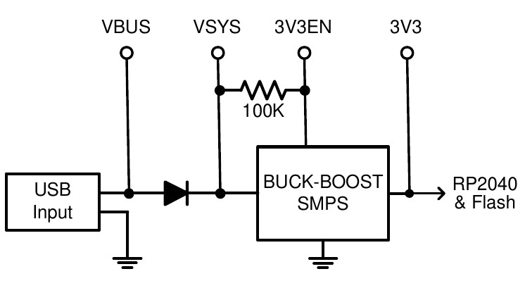
The Raspberry Pi Pico has a flexible power system.
The input voltage from either the USB or VBUS inputs is connected through a Schottky diode to the buck-boost SMPS (Switch Mode Power Supply) which has an output of 3.3V. The SMPS will accommodate input voltages from 1.8V to 5.5V allowing the PicoMite to run from a wide range of power sources including batteries.
External circuitry can be powered by VBUS (normally 5V) or by the 3V3 (3.3V) output which can source up to 300mA.
For embedded controller applications generally an external power source (other than USB) is required and this can be connected to VSYS via a Schottky diode. This will allow the PicoMite to be powered by whichever supply is producing the highest voltage (USB or VSYS). The diodes will prevent feedback into the lower voltage supply.
To minimize power supply noise it is possible to ground 3V3EN to turn off the SMPS. When shutdown the converter will stop switching, internal control circuitry will be turned off and the load disconnected. You can then power the board via a 3.3V linear regulator feeding into the 3V3 pin.
Clock Speed
By default the clock speed for the RP2040 used in the Raspberry Pi Pico is 200MHz and for the RP2350 used in the Raspberry Pi Pico 2 is 150MHz. These are the recommended maximums.
Using the OPTION CPUSPEED command, most RP2040 CPUs can be overclocked up to 420MHz or 396MHz for the RP2350 (PicoMite and WebMite only). They can also run slower to a minimum of 48MHz. This option is saved and will be reapplied on power up. When changing the clock speed the PicoMite firmware will be reset then rebooted so the USB connection will be disconnected.
Versions with Video @ 640x400 resolution have the clock set to 252MHz however this can be changed using OPTION RESOLUTION to 252MHz, 315MHz or 378MHz.
At other video resolutions the clock speed is fixed at 283.2MHz, 324MHz, 360MHz ,372MHz or 375MHz depending on the video resolution selected and this cannot be changed.
Nearly all tested Raspberry Pi Picos have worked correctly at 380MHz or more, so overclocking can be useful. If the processor fails to restart at its new clock speed you can reset it by loading Clear_flash.uf2 to reset the Pico to its factory fresh state.
Power Consumption
The power consumption is dependent on the clock speed, however at the default clock speed (200MHz for the RP2040 and 150MHz for the RP2350), the typical power consumption is 25mA. This does not include any current sourced or sunk by the I/O pins or the 3V3 pin:
The power consumption for the WebMite version for the Raspberry Pi Pico W is the same at 20mA with the WiFi disabled but, when the WiFi is enabled, the power consumption will rise to 40 to 70mA.
Using MMBasic
Commands and Program Input
At the command prompt you can enter a command and it will be immediately run. Most of the time you will do this to tell the PicoMite firmware to do something like run a program or set an option. But this feature also allows you to test out commands at the command prompt.
To enter a program the easiest method is to use the EDIT command. This will invoke the full screen program
editor which is built into the PicoMite firmware and is described later in this manual. It includes advanced
features such as search and copy, cut and paste to and from a clipboard.
You could also compose the program on your desktop computer using something like Notepad and then
transfer it to the Raspberry Pi Pico via the XModem protocol (see the XMODEM command) or by streaming it
up the console serial link (see the AUTOSAVE command).
A third and convenient method of writing and debugging a program is to use MMEdit. This is a program running on your Windows computer which allows you to edit your program on your computer then transfer it to the PicoMite with a single click of the mouse. MMEdit was written by Jim Hiley and is free to download and use. To learn more and get it go to: https://geoffg.net/mmedit.html
One thing that you cannot do is use the old BASIC way of entering a program which was to prefix each line with a line number. Line numbers are optional in MMBasic so you can still use them if you wish but if you enter a line with a line number at the prompt MMBasic will simply execute it immediately.
Program Structure
A BASIC program starts at the first line and continues until it runs off the end of the program or hits an END command - at which point MMBasic will display the command prompt (>) on the console and wait for something to be entered.
A program consists of a number of statements or commands, each of which will cause the BASIC interpreter to do something (the words statement and command generally mean the same and are used interchangeably). Normally each statement is on its own line but you can have multiple statements in the one line separated by the colon character (:). For example.
A = 24.6 : PRINT A
Appendix G – Programming in BASIC - A Tutorial at the rear of this manual provides a comprehensive tutorial on the language which will take you through the fundamentals in an easy to read format with lots of examples.
Editing the Command Line
When entering a line at the command prompt the line can be edited using the left and right arrow keys to move along the line, the Delete key to delete a character, the Backspace to delete before the cursor and the Insert key to switch between insert and overwrite modes.
Home/End will move to the beginning/end of the line and Home pressed twice will terminate the edit. At any point the Enter key will send the line to MMBasic which will execute it. The up and down arrow keys will move through a history of previously entered command lines which can be edited and reused.
Shortcut Keys
The function keys on the keyboard or the serial console can be used at the command prompt to automatically enter common commands. These function keys will insert the text followed by the Enter key so that the command is immediately executed:
- F2 : RUN
- F3 : LIST
- F4 : EDIT
- F10 : AUTOSAVE
- F11 : XMODEM RECEIVE
- F12 : XMODEM SEND
Function keys F1, and F5 to F9 can be programmed with custom text. See the OPTION FNKey command.
Interrupting A Running Program
A program is set running by the RUN command. You can interrupt MMBasic and the running program at any time by typing CTRL-C on the console input and MMBasic will return to the command prompt.
Setting Options
Many options can be set by using commands that start with the keyword OPTION. They are listed in their own
section of this manual. For example, you can change the CPU clock speed with the command:
OPTION CPUSPEED speed
Saved Variables
Because the PicoMite does not necessarily have a normal storage system it needs to save data that can be recovered when power is restored. This can be done with the VAR SAVE command which will save the variables listed on its command line in non-volatile flash memory. The space reserved for saved variables is 16KB.
These variables can be restored with the VAR RESTORE command which will add all the saved variables to the variable table of the running program. Normally this command is placed near the start of a program so that the variables are ready for use by the program.
This facility is intended for saving calibration data, user selected options and other items which change infrequently. It should not be used for high-speed saves as you may wear out the flash memory. The flash used for the Raspberry Pi Pico has a high endurance but this can be exceeded by a program that repeatedly saves variables. If you do want to save data often you should add a real time clock chip. The RTC commands can then be used to store and retrieve data from the RTC's battery backed memory. See the RTC command for more details.
Watchdog Timer
The main use for the PicoMite is as an embedded controller. It can be programmed in MMBasic and when the program is debugged and ready for "prime time" the OPTION AUTORUN configuration setting can be turned on. The module will then automatically run its program when power is applied and act as a custom circuit performing some special task. The user need not know anything about what is running inside it. However, there is the possibility that a fault in the program could cause MMBasic to generate an error and return to the command prompt. This would be of little use in an embedded situation as the PicoMite would not have anything connected to the console. Another possibility is that the BASIC program could get itself stuck in an endless loop for some reason. In both cases the visible effect would be the same… the program would stop running until the power was cycled.
To guard against this the watchdog timer can be used. This is a timer that counts down to zero and when it reaches zero the processor will be automatically restarted (the same as when power was first applied), this will occur even if MMBasic was sitting at the command prompt. Following the restart the automatic variable MM.WATCHDOG will be set to true to indicate that the restart was caused by a watchdog timeout.
The WATCHDOG command should be placed in strategic locations in the program to keep resetting the timer and therefore preventing it from counting down to zero. Then, if a fault occurs, the timer will not be reset, it will count down to zero and the program will be restarted (assuming the AUTORUN option is set).
PIN Security
Sometimes it is important to keep the data and program in an embedded controller confidential. In the PicoMite this can be done by using the OPTION PIN command. This command will set a pin number (which is stored in flash) and whenever the PicoMite returns to the command prompt (for whatever reason) the user at the console will be prompted to enter the PIN number. Without the correct PIN the user cannot get to the command prompt and their only option is to enter the correct PIN or reboot the PicoMite. When it is rebooted the user will still need the correct PIN to access the command prompt. Because an intruder cannot reach the command prompt they cannot list or copy a program, they cannot change the program or change any aspect of MMBasic or the PicoMite. Once set the PIN can only be removed by providing the correct PIN as set in the first place. If the number is lost the only method of recovery is to reload the PicoMite firmware (which will erase the program and all options). There are other time consuming ways of accessing the data (such as using a programmer to examine the flash memory) so this should not be regarded as the ultimate security but it does act as a significant deterrent.
The Library
Using the LIBRARY feature it is possible to create BASIC functions, subroutines and embedded fonts and add them to MMBasic to make them permanent and part of the language. For example, you might have written a series of subroutines and functions that perform sophisticated bit manipulation; these could be stored as a library and become part of MMBasic and perform the same as other built-in functions that are already part of the language. An embedded font can also be added the same way and used just like a normal font.
To install components into the library you need to write and test the routines as you would with any normal
BASIC routines. When they are working correctly you can use the LIBRARY SAVE command. This will
transfer the routines (as many as you like) to a non-visible part of flash memory where they will be available to any BASIC program but will not show when the LIST command is used and will not be deleted when a new program is loaded or NEW is used. However, the saved subroutines and functions can be called from within the main program and can even be run at the command prompt (just like a built-in command or function).
Some points to note:
- Library routines act exactly like normal BASIC code and can consist of any number of subroutines, functions, embedded C routines and fonts. The only difference is that they do not show when a program is listed and are not deleted when a new program is loaded.
- Library routines can create and access global variables and are subject to the same rules as the main
program – for example, respecting
OPTION EXPLICITif it is set. - When the routines are transferred to the library MMBasic will compress them by removing comments, extra spaces, blank lines and the hex codes in embedded C routines and fonts. This makes the library space efficient, especially when loading large fonts. Following the save the program area is cleared.
- You can use the
LIBRARY SAVEcommand multiple times. With each save the new contents of the program space are appended to the already existing code in the library. - You can use line numbers in the library but you cannot use a line number on an otherwise empty line as
the target for a GOTO, etc. This is because the
LIBRARY SAVEcommand will remove any blank lines. - You can use READ commands in the library but they will default to reading DATA statements in the main program memory. If you want to read from DATA statements in the library you must use the RESTORE command before the first READ command. This will reset the pointer to the library space.
- The library is saved to program flash memory Slot 3 and this will not be available for storing a program if
LIBRARY SAVEis used. - You can see what is in the library by using the
LIBRARY LISTcommand which will list the contents of the library space. - The
LIBRARYcontents can be saved to disk usingLIBRARY DISK SAVE fname$and restored usingLIBRARY DISK LOAD fname$
To delete the routines in the library space you use the LIBRARY DELETE command. This will clear the space
and return the Flash Slot 3 used by the library back to being available for storage for normal programs. The
only other way to delete a library is to use OPTION RESET.
Program Initialisation
The library can also include code that is not contained within a subroutine or function. This code (if it exists)
will be run automatically before a program starts running (ie, via the RUN command). This feature can be used
to initialise constants or setup MMBasic in some way. For example, if you wanted to set some constants you
could include the following lines in the library code:
CONST TRUE = 1
CONST FALSE = 0
For all intents and purposes, the identifiers TRUE and FALSE have been added to the language and will be available to any program that is run on the PicoMite.
MM.STARTUP
There may be a need to execute some code on initial power up, perhaps to initialise some hardware, set some
options or print a custom start-up banner. This can be accomplished by creating a subroutine with the name
MM.STARTUP. When the PicoMite is first powered up or reset it will search for this subroutine and, if found,
it will be run once.
For example, if the PicoMite has a real time clock attached, the program could contain the following code:
SUB MM.STARTUP
RTC GETTIME
END SUB
This would cause the internal clock within MMBasic to be set to the current time on every power up or reset.
After the code in MM.STARTUP has been run MMBasic will continue with running the rest of the program in
program memory. If there is no other code MMBasic will return to the command prompt.
Note that you should not use MM.STARTUP for general setup of MMBasic (like dimensioning arrays, opening
communication channels, etc) before running a program. The reason is that when you use the RUN command
MMBasic will clear the interpreter's state ready for a fresh start.
MM.PROMPT
If a subroutine with this name exists it will be automatically executed by MMBasic instead of displaying the command prompt. This can be used to display a custom prompt, set colours, define variables, etc all of which will be active at the command prompt.
Note that MMBasic will clear all variables and I/O pin settings when a program is run so anything set in this subroutine will only be valid for commands typed at the command prompt (i.e. in immediate mode). As an example the following will display a custom prompt:
SUB MM.PROMPT
PRINT TIME$ "> ";
END SUB
Note that while constants can be defined, they will not be visible because a constant defined inside a subroutine is local to a subroutine. However, DIM will create variables that are global that that should be used instead.
Full Screen Editor
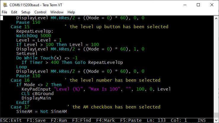
An important productivity feature is the built-in full screen editor. When running it looks like this:
The editor operates with:
- The serial console using a VT100 supported terminal emulator (such as Tera Term) on all versions.
- The VGA or HDMI video output (on versions with this feature).
- An attached LCD panel that has been configured with
OPTION LCDPANEL CONSOLE.
When the editor starts up the cursor will be automatically positioned at the last place that you were editing or, if your program had just been stopped by an error, the cursor will be positioned at the line that caused the error. At the bottom of the screen the status line lists details such as the current cursor position and the common functions supported by the editor.
If you have previously used an editor like Windows Notepad you will find that the operation of this editor is familiar. The arrow keys will move the cursor around in the text, home and end will take you to the beginning or end of the line. Page up and page down will do what their titles suggest. The delete key will delete the character at the cursor and backspace will delete the character before the cursor. The insert key will toggle between insert and overtype modes.
About the only unusual key combination is that two home key presses will take you to the start of the program and two end key presses will take you to the end.
At the bottom of the screen the status line will list the various function keys used by the editor and their action.
In more details these are:
| Key | Name | Description |
|---|---|---|
| ESC | This will cause the editor to abandon all changes and return to the command prompt with the program memory unchanged. If you have changed the text you will be asked if you really what want to abandon your changes. | |
| F1 | SAVE | This will save the program to program memory and return to the command prompt. |
| F2 | RUN | This will save the program to program memory and immediately run it. |
| F3 | FIND | This will prompt for the text that you want to search for. When you press enter the cursor will be placed at the start of the first entry found. |
| SHIFT - F3 | Once you have used the search function you can repeat the search by pressing SHIFT-F3. | |
| F4 | MARK | This is described in detail below. |
| F5 | PASTE | This will insert (at the current cursor position) the text that had been previously cut or copied (see below). |
If you pressed the mark key (F4) the editor will change to the mark mode. In this mode you can use the arrow keys to mark a section of text which will be highlighted in reverse video. You can then delete, cut or copy the marked text. In this mode the status line will change to show the functions of the function keys in the mark mode.
These keys are:
| Key | Name | Description |
|---|---|---|
| ESC | Will exit mark mode without changing anything. | |
| F4 | CUT | Will copy the marked text to the clipboard and remove it from the program. |
| F5 | COPY | Will just copy the marked text to the clipboard. |
| DELETE | Will delete the marked text leaving the clipboard unchanged. |
You can also use control keys instead of the function keys listed above. These control keystrokes are:
| function key | control key | function key | control key | function key | control key | function key | control key | |||
|---|---|---|---|---|---|---|---|---|---|---|
| UP | Ctrl-E | DOWN | Ctrl-X | LEFT | Ctrl-S | RIGHT | Ctrl-D | |||
| PageUp | Ctrl-P | PageDn | Ctrl-L | HOME | Ctrl-U | END | Ctrl-K | |||
| F1 | Ctrl-Q | F2 | Ctrl-W | DEL | Ctrl-] | INSERT | Ctrl-N | |||
| F4 | Ctrl-T | F5 | Ctrl-Y | F3 | Ctrl-R | Shift - F3 | Ctrl-G |
The best way to learn how to use the editor is to simply fire it up and experiment. 🔥
The editor is a very productive method of writing a program. With the command EDIT you can enter your program then, by pressing the F2 key, you can save and run the program.
If your program stops with an error pressing the function key F4 at the command prompt will load the editor and position the cursor at the line that caused the error. This edit/run/edit cycle is very fast.
Long Lines
Long lines will only display the first part of the line up to the display’s right hand margin. The rest of the line beyond the right hand margin is still there but it is not displayed and cannot be edited.
If you want to edit a very long line you can position the cursor near the right hand margin and press Enter. This will split the long line into two and both parts can be separately edited. To rejoin the line use the Delete or Backspace key to remove the line break that you previously entered.
Alternatively, you can enable continuation lines (OPTION CONTINUATION LINES ON) before entering the editor. The allows you to use a space followed by and underscore character at the end of a line to indicate that the next line is a continuation and should be concatenated in order for the program to run.
The concatenation occurs when the file is saved and when re-edited long lines are automatically split up as the file is read into the editor. The line breaks may not be in the same place but the editor attempts to place them in sensible positions (at the end of words etc.).
There are no limits on where continuation characters are placed. For example, they can be in the middle of a quoted string. The limit of a maximum of 255 characters in a concatenated line still applies and the editor will not allow you to exit if a line is too long.
Using a Mouse
Versions of the PicoMite firmware that support VGA/HDMI (in both the RP2040 and RP2350 versions) also supports the use of a PS2 or USB mouse in the editor. For the details of connecting a mouse see the heading Keyboard/Mouse/Gamepad later in this manual.
If you start the editor with a mouse plugged in and are in video MODE 1 with colour coding enabled you will
see a character highlighted with red on a white background. This highlight can be moved using the mouse.
Left clicking on the mouse will move the edit cursor to that position (ie, the same as using the cursor keys).
Right clicking the mouse is the same as pressing F4 on the keyboard and clicking the scroll wheel is the same as F5.
This means that in the editor’s normal mode you can position the mouse cursor and by right clicking the editor will enter mark mode (cut-and-copy) with the cursor starting where the mouse cursor was. Then moving the mouse and then left clicking will highlight the characters from the mark position to the new mouse position.
Right clicking (same as F4) will cut the highlighted region to the clipboard while clicking the scroll wheel (same as F5) will copy the highlighted text to the clipboard without deleting it from the text. Both will return the editor to normal mode.
In normal mode the contents of the clipboard can be inserted into the text by moving the mouse to the new position and clicking the scroll wheel (same as F5).
Colour Coded Editor Display
The editor can colour code the edited program with keywords, numbers and comments displayed in different colours. This feature can be turned on or off with the command:
OPTION COLOURCODE ON or OPTION COLOURCODE OFF
This option is saved in non-volatile memory and automatically applied on start-up.
Variables and Expressions
In MMBasic command names, function names, labels, variable names, file names, etc are not case sensitive, so that "Run" and "RUN" are equivalent and "dOO" and "Doo" refer to the same variable.
Variables
Variables can start with an alphabetic character or underscore and can contain any alphabetic or numeric character, the period (.) and the underscore (_). They may be up to 31 characters long. A variable name or a label must not be the same as a command, function or one of the following keywords:
THEN, ELSE, GOTO, GOSUB, TO, STEP, FOR, WHILE, UNTIL, LOAD, MOD, NOT, AND, OR, XOR, AS.
Eg, step = 5 is illegal as STEP is a keyword.
MMBasic supports three types of variables:
-
Double Precision Floating Point.
These can store a number with a decimal point and fraction (eg,
45.386) however they will lose accuracy when more than 14 digits of precision are used. Floating point variables are specified by adding the suffix!to a variable's name (eg,i!,nbr!, etc). They are also the default when a variable is created without a suffix (eg,i,nbr, etc). -
64-bit Signed Integer.
These can store positive or negative numbers with up to 19 decimal digits without losing accuracy but they cannot store fractions (i.e. the part following the decimal point). These are specified by adding the suffix
%to a variable's name. For example,i%,nbr%, etc. -
A String.
A string will store a sequence of characters (eg,
"Tom"). Each character in the string is stored as an eight bit number and can therefore have a decimal value of0to255. String variable names are terminated with a$symbol (eg,name$,s$, etc). Strings can be up to 255 characters long.
Note that it is illegal to use the same variable name with different types. Eg, using nbr! and nbr% in the
same program would cause an error.
Most programs use floating point variables for arithmetic as these can deal with the numbers used in typical situations and are more intuitive than integers when dealing with division and fractions. So, if you are not bothered with the details, always use floating point.
Constants
Numeric constants may begin with a numeric digit (0-9) for a decimal constant, &H for a hexadecimal
constant, &O for an octal constant or &B for a binary constant. For example &B1000 is the same as the
decimal constant 8. Constants that start with &H, &O or &B are always treated as 64-bit unsigned integer
constants.
Decimal constants may be preceded with a minus (-) or plus (+) and may be terminated with E followed by an
exponent number to denote exponential notation. For example 1.6E+4 is the same as 16000.
When a constant number is used it will be assumed that it is an integer if a decimal point or exponent is not
used. For example, 1234 will be interpreted as an integer while 1234.0 will be interpreted as a floating point
number.
String constants must be surrounded by double quote marks ("). Eg, "Hello World".
OPTION DEFAULT
A variable can be used without a suffix (i.e. !, % or $) and in that case MMBasic will use the default type of
floating point. For example, the following will create a floating point variable:
Nbr = 1234`
However. the default can be changed with the OPTION DEFAULT command. For example, OPTION DEFAULT INTEGER will specify that all variables without a specific type will be integer. So, the following
will create an integer variable:
OPTION DEFAULT INTEGER
Nbr = 1234
The default can be set to FLOAT (which is the default when a program is run), INTEGER, STRING or NONE. In the latter all variables must be specifically typed otherwise an error will occur.
The OPTION DEFAULT command can be placed anywhere in the program and changed at any time but good
practice dictates that if it is used it should be placed at the start of the program and left unchanged.
OPTION EXPLICIT
By default MMBasic will automatically create a variable when it is first referenced. So, Nbr = 1234 will create the variable and set it to the number 1234 at the same time. This is convenient for short and quick programs but it can lead to subtle and difficult to find bugs in large programs. For example, in the third line of this fragment the variable Nbr has been misspelt as Nbrs. As a consequence the variable Nbrs would be created with a value of zero and the value of Total would be wrong.
Nbr = 1234
Incr = 2
Total = Nbrs + Incr
The OPTION EXPLICIT command tells MMBasic to not automatically create variables. Instead they must be
explicitly defined using the DIM, LOCAL or STATIC commands (see below) before they are used. The use of
this command is recommended to support good programming practice. If it is used it should be placed at the
start of the program before any variables are used.
DIM and LOCAL
The DIM and LOCAL commands can be used to define a variable and set its type and are mandatory when the
OPTION EXPLICIT command is used.
The DIM command will create a global variable that can be seen and used throughout the program including
inside subroutines and functions. However, if you require the definition to be visible only within a subroutine
or function, you should use the LOCAL command at the start of the subroutine or function. LOCAL has
exactly the same syntax as DIM.
If LOCAL is used to specify a variable with the same name as a global variable then the global variable will be
hidden to the subroutine or function and any references to the variable will only refer to the variable defined by
the LOCAL command. Any variable created by LOCAL will vanish when the program leaves the subroutine.
At its simplest level DIM and LOCAL can be used to define one or more variables based on their type suffix or
the OPTION DEFAULT in force at the time. For example:
DIM nbr%, s$
But it can also be used to define one or more variables with a specific type when the type suffix is not used:
DIM INTEGER nbr, nbr2, nbr3, etc
In this case nbr, nbr2, nbr3, etc are all created as integers. When you use the variable within a program you do
not need to specify the type suffix. For example, MyStr in the following works perfectly as a string variable:
DIM STRING MyStr
MyStr = "Hello"
The DIM and LOCAL commands will also accept the Microsoft practice of specifying the variable's type after
the variable with the keyword "AS". For example:
DIM nbr AS INTEGER, s AS STRING
In this case the type of each variable is set individually (not as a group as when the type is placed before the list of variables).
The variables can also be initialised while being defined. For example:
DIM INTEGER a = 5, b = 4, c = 3
DIM s$ = "World", i% = &H8FF8F
DIM msg AS STRING = "Hello" + " " + s$
The value used to initialise the variable can be an expression including user defined functions.
The DIM or LOCAL commands are also used to define an array and all the rules listed above apply when
defining an array. For example, you can use:
DIM INTEGER nbr(10), nbr2, nbr3(5,8)
When initialising an array the values are listed as comma separated values with the whole list surrounded by brackets. For example:
DIM INTEGER nbr(5) = (11, 12, 13, 14, 15, 16)
or
DIM days(7) AS STRING = ("","Sun","Mon","Tue","Wed","Thu","Fri","Sat")
STATIC
Inside a subroutine or function it is sometimes useful to create a variable which is only visible within the
subroutine or function (like a LOCAL variable) but retains its value between calls to the subroutine or function.
You can do this by using the STATIC command. STATIC can only be used inside a subroutine or function and
uses the same syntax as LOCAL and DIM. The difference is that its value will be retained between calls to the
subroutine or function (i.e. it will not be initialised on the second and subsequent calls).
For example, if you had the following subroutine and repeatedly called it, the first call would print 5, the second 6, the third 7 and so on.
SUB Foo
    STATIC var = 5
    PRINT var
    var = var + 1
END SUB
Note that the initialisation of the static variable to 5 (as in the above example) will only take effect on the first
call to the subroutine. On subsequent calls the initialisation will be ignored as the variable had already been
created on the first call.
As with DIM and LOCAL the variables created with STATIC can be float, integers or strings and arrays of
these with or without initialisation. The length of the variable name created by STATIC and the length of the
subroutine or function name added together cannot exceed 31 characters.
CONST
Often it is useful to define an identifier that represents a value without the risk of the value being accidently changed - which can happen if variables were used for this purpose (this practice encourages another class of difficult to find bugs). Using the CONST command you can create an identifier that acts like a variable but is set to a value that cannot be changed. For example:
CONST InputVoltagePin = 31
CONST MaxValue = 2.4
The identifiers can then be used in a program where they make more sense to the casual reader than simple numbers. For example:
IF PIN(InputVoltagePin) > MaxValue THEN SoundAlarm
A number of constants can be created on the one line:
CONST InputVoltagePin = 31, MaxValue = 2.4, MinValue = 1.5
The value used to initialise the constant is evaluated when the constant is created and can be an expression including user defined functions.
The type of the constant is derived from the value assigned to it; so for example, MaxValue above will be a
floating point constant because 2.4 is a floating point number. The type of a constant can also be explicitly set
by using a type suffix (i.e. !, % or $) but it must agree with its assigned value.
Special Characters in Strings
Special, non-printable characters can be inserted in string constants using the backslash (ie, \) as an escape
symbol. To enable this facility the command OPTION ESCAPE must be placed at the start of the program.
These are the valid escape sequences:
| Hex Value | Description | |
|---|---|---|
\a | 07 | Alert (Beep, Bell) |
\b | 08 | Backspace |
\e | 1B | Escape character |
\f | 0C | Formfeed Page Break |
\n | 0A | Newline (Line Feed) |
\r | 0D | Carriage Return |
\q | 22 | Quote symbol |
\t | 09 | Horizontal Tab |
\v | 0B | Vertical Tab |
\\ | 5C | Backslash |
\nnn | any | The byte whose value is given by nnn interpreted as a decimal number |
\&hh | any | The byte whose value is given by hh… interpreted as a hexadecimal number |
For example, the following will print the words Hello and World on separate lines:
OPTION ESCAPE
PRINT "Hello\r\nWorld"
Expressions and Operators
MMBasic will evaluate a mathematical expression using the standard mathematical rules. For example, multiplication and division are performed first followed by addition and subtraction. These are called the rules of precedence and are detailed below.
This means that 2 + 3 * 6 will resolve to 20, so will 5 * 4 and also 10 + 4 * 3 – 2.
If you want to force the interpreter to evaluate parts of the expression first you can surround that part of the
expression with brackets. For example, (10 + 4) * (3 – 2) will resolve to 14 not 20 as would have been the case
if the brackets were not used. Using brackets does not appreciably slow down the program so you should use
them liberally if there is a chance that MMBasic will misinterpret your intention.
The following operators, in order of precedence, are implemented in MMBasic. Operators that are on the same
level (for example + and -) are processed with a left to right precedence as they occur on the program line.
| Arithmetic operators | |
|---|---|
^ | Exponentiation (eg, b^n means bn) |
* / \ MOD | Multiplication, division, integer division and modulus (remainder) |
+ - | Addition and subtraction |
| Shift operators | |
|---|---|
x << y x >> y | These operate in a special way.<< means that the value returned will be the value of x shifted by y bits to the left while >> means the same only right shifted.They are integer functions and any bits shifted off are discarded and any bits introduced are set to zero. |
| Logical operators | |
|---|---|
NOT INV | invert the logical value on the right (eg, NOT(a=b) is a<>b) or bitwise inversion of the value on the right (eg, a = INV b) |
<> < > <= =< >= => | Inequality, less than, greater than, less than or equal to, less than or equal to (alternative version), greater than or equal to, greater than or equal to (alternative version) |
= | equality |
AND OR XOR | Conjunction, disjunction, exclusive or |
For Microsoft compatibility the operators AND, OR and XOR are integer bitwise operators. For example:
> PRINT (3 AND 6)
2
Because these operators can act as both logical operators (for example, IF a=5 AND b=8 THEN …) and as bitwise operators (eg, y% = x% AND &B1010) the interpreter will be confused if they are mixed in the same expression. So, always evaluate logical and bitwise expressions
in separate expressions.
The other logical operations result in the integer 0 (zero) for false and 1 for true. For example PRINT 4 >= 5 will print the number 0 on the output and the expression A = 3 > 2 will store +1 in A.
The NOT operator will invert the logical value on its right (it is not a bitwise invert) while the INV operator
will perform a bitwise invert. Both of these have the highest precedence so they will bind tightly to the next
value. For normal use of NOT or INV the expression to be operated on should be placed in brackets. Eg:
IF NOT (A = 3 OR A = 8) THEN …
| String operators | |
|---|---|
+ | Join two strings |
<> < > <= =< >= => | Inequality, less than, greater than, less than or equal to, less than or equal to (alternative version), greater than or equal to, greater than or equal to (alternative version) in order of ascii value. |
= | Equality |
String comparisons respect case. For example "A" is greater than "a".
Mixing Floating Point and Integers
MMBasic automatically handles conversion of numbers between floating point and integers. If an operation
mixes both floating point and integers (eg, PRINT A% + B!) the integer will be converted to a floating point
number first, then the operation performed and a floating point number returned. If both sides of the operator
are integers then an integer operation will be performed and an integer returned.
The one exception is the normal division (/) which will always convert both sides of the expression to a
floating point number and then returns a floating point number. For integer division you should use the integer
division operator \.
MMBasic functions will return a float or integer depending on their characteristics. For example, PIN() will
return an integer when the pin is configured as a digital input but a float when configured as an analog input.
If necessary you can convert a float to an integer with the INT() function. It is not necessary to specifically
convert an integer to a float but if it was needed the integer value could be assigned to a floating point variable
and it will be automatically converted in the assignment.
64-bit Unsigned Integers
MMBasic supports 64-bit signed integers. This means that there are 63 bits for holding the number and one bit (the most significant bit) which is used to indicate the sign (positive or negative). However it is possible to use full 64-bit unsigned numbers as long as you do not do any arithmetic on the numbers.
64-bit unsigned numbers can be created using the &H, &O or &B prefixes to a number and these numbers can
be stored in an integer variable. You then have a limited range of operations that you can perform on these.
They are << (shift left), >> (shift right), AND (bitwise and), OR (bitwise or), XOR (bitwise exclusive or), INV
(bitwise inversion), = (equal to) and <> (not equal to). Arithmetic operators such as division or addition may
be confused by a 64-bit unsigned number and could return nonsense results.
To display 64-bit unsigned numbers you should use the HEX$(), OCT$() or BIN$() functions.
For example, the following 64-bit unsigned operation will return the expected results:
> X% = &HFFFF0000FFFF0044
> Y% = &H800FFFFFFFFFFFFF
> X% = X% AND Y%
> PRINT HEX$(X%, 16)
800F0000FFFF0044
Subroutines and Functions
Subroutines and Functions
A program defined subroutine or function is simply a block of programming code that is contained within a module and can be called from anywhere within your program. It is the same as if you have added your own command or function to the language.
Subroutines
A subroutine acts like a command and it can have arguments (sometimes called a parameter list). In the definition of the subroutine they look like this:
SUB MYSUB arg1, arg2$, arg3
<statements>
<statements>
END SUB
And when you call the subroutine you can assign values to the arguments. For example:
MYSUB 23, "Cat", 55
Inside the subroutine arg1 will have the value 23, arg2$ the value of "Cat", and so on. The arguments act
like ordinary variables but they exist only within the subroutine and will vanish when the subroutine ends. You
can have variables with the same name in the main program and they will be hidden by the arguments defined
for the subroutine.
When calling a subroutine you can supply less than the required number of values and in that case the missing values will be assumed to be either zero or an empty string. You can also leave out a value in the middle of the list and the same will happen. For example:
MYSUB 23, , 55
Will result in arg2$ being set to the empty string "".
Rather than using the type suffix (eg, the $ in arg2$) you can use the suffix AS <type> in the definition of the
subroutine argument and then the argument will be known as the specified type, even when the suffix is not
used. For example:
SUB MYSUB arg1, arg2 AS STRING, arg3
IF arg2 = "Cat" THEN …
END SUB
Inside a subroutine you can define a variable using LOCAL (which has the same syntax as DIM). This variable
will only exist within the subroutine and will vanish when the subroutine exits.
Functions
Functions are similar to subroutines with the main difference being that the function is used to return a value in an expression. The rules for the argument list in a function are similar to subroutines. The only difference is that brackets are required around the argument list when you are calling a function, even if there are no arguments (brackets are optional when calling a subroutine).
To return a value from the function you assign a value to the function's name within the function. If the function's name is terminated with a $, a % or a ! the function will return that type, otherwise it will return whatever the OPTION DEFAULT is set to. You can also specify the type of the function by adding AS <type> to the end of the function definition.
For example:
FUNCTION Fahrenheit(C) AS FLOAT
Fahrenheit = C * 1.8 + 32
END FUNCTION
Passing Arguments by Reference
If you use an ordinary variable (i.e., not an expression) as the value when calling a subroutine or a function, the argument within the subroutine/function will point back to the variable used in the call and any changes to the argument will also be made to the supplied variable. This is called passing arguments by reference.
For example, you might define a subroutine to swap two values, as follows:
SUB Swap a, b
LOCAL t
t = a
a = b
b = t
END SUB
In your calling program you would use variables for both arguments:
Swap nbr1, nbr2
And the result will be that the values of nbr1 and nbr2 will be swapped.
For this to work the type of the variable passed (eg, nbr1) and the defined argument (eg, a) must be the same (in the above example both default to float).
If you want to use an argument as a general purpose variable inside a subroutine or function (ie, change its value) you should prefix its definition with the keyword BYVAL. This instructs MMBasic to always use the value of the argument, even if it is a variable, and to never point back to the variable used in the call. This is because another user of your routine may unwittingly use a variable in their call and that variable could be "magically" changed by your routine if you did not use BYVAL.
Passing Arrays
Single elements of an array can be passed to a subroutine or function and they will be treated the same as a normal variable. For example, this is a valid way of calling the Swap subroutine (discussed above):
Swap dat(i), dat(i + 1)
This type of construct is often used in sorting arrays.
You can also pass one or more complete arrays to a subroutine or function by specifying the array with empty brackets instead of the normal dimensions. For example, a(). In the subroutine or function definition the associated parameter must also be specified with empty brackets. The type (i.e., float, integer or string) of the argument supplied and the parameter in the definition must be the same.
In the subroutine or function the array will inherit the dimensions of the array passed and these must be respected when indexing into the array. If required the dimensions of the array could be passed as additional arguments to the subroutine or function or it could find these via the BOUND() function. The array is passed by reference which means that any changes made to the array within the subroutine or function will also apply to the supplied array.
For example, when the following is run the words Hello World will be printed out:
DIM MyStr$(5, 5)
MyStr$(4, 4) = "Hello" : MyStr$(4, 5) = "World"
Concat MyStr$()
PRINT MyStr$(0, 0)
SUB Concat arg$()
arg$(0,0) = arg$(4, 4) + " " + arg$(4, 5)
END SUB
Early Exit
There can be only one END SUB or END FUNCTION for each definition of a subroutine or function. To exit
early from a subroutine (i.e., before the END SUB command has been reached) you can use the EXIT SUB
command. This has the same effect as if the program reached the END SUB statement. Similarly you can use
EXIT FUNCTION to exit early from a function.
Recursion
Recursion is where a subroutine or function calls itself. You can do recursion in MMBasic but there are a number of issues (these are a direct consequence of the limitations of microcontrollers and the BASIC language):
- There is a fixed limit to the depth of recursion. In the PicoMite firmware this is 50 levels.
- If you have many arguments to the subroutine or function and many
LOCALvariables (especially strings) you could easily run out of memory before reaching the 50 level limit. - Any
FOR…NEXTloops andDO…LOOPs will be corrupted if the subroutine or function is recursively called from within these loops.
Examples
There is often the need for a special command or function to be implemented in MMBasic but in many cases these can be constructed using an ordinary subroutine or function which will then act exactly the same as a built in command or function.
For example, sometimes there is a requirement for a TRIM function which will trim specified characters from
the start and end of a string. The following provides an example of how to construct such a simple function in
MMBasic.
The first argument to the function is the string to be trimmed and the second is a string containing the
characters to trim from the first string. RTrim$() will trim the specified characters from the end of the string,
LTrim$() from the beginning and Trim$() from both ends.
- trim any characters in c$ from the start and end of s$
Function Trim$(s$, c$)
Trim$ = RTrim$(LTrim$(s$, c$), c$)
End Function
- trim any characters in c$ from the end of s$
Function RTrim$(s$, c$)
RTrim$ = s$
Do While Instr(c$, Right$(RTrim$, 1))
RTrim$ = Mid$(RTrim$, 1, Len(RTrim$) - 1)
Loop
End Function
- trim any characters in c$ from the start of s$
Function LTrim$(s$, c$)
LTrim$ = s$
Do While Instr(c$, Left$(LTrim$, 1))
LTrim$ = Mid$(LTrim$, 2)
Loop
End Function
As an example of using these functions:
S$ = "
****23.56700
PRINT Trim$(s$, " ")

"
Will give "****23.56700"
PRINT Trim$(s$, " *0")
Will give "23.567"
PRINT LTrim$(s$, " *0")
Will give "23.56700"
Video Output
VGA Video
For versions of the firmware that support a VGA video output the following diagram illustrates how to attach such a monitor. The VGA output is automatically enabled at startup – there are no options that need to be set.
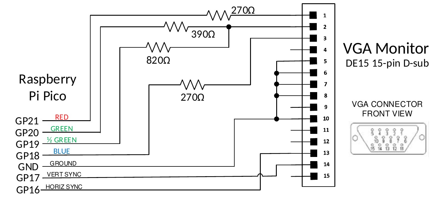
| Raspberry Pi Pico | Signal | Resistor | VGA Monitor DE15 15-pin D-sub |
|---|---|---|---|
| GP21 | RED | 270Ω | 1 |
| GP20 | GREEN | 390Ω | 2 |
| GP19 | ½ GREEN | 820Ω | 2 |
| GP18 | BLUE | 270Ω | 3 |
| GND | GROUND | 5, 6, 7, 8, 10 | |
| GP17 | VERT SYNC | 14 | |
| GP16 | HORIZ SYNC | 13 |
The output is in the standard VGA format with a pixel rate of 25.175MHz and a frame rate of 60Hz. There are two or three modes which can be selected using the MODE command:
- MODE 1 Monochrome with a resolution of 640 x 480 (default at startup)
- MODE 2 16 colours with a resolution of 320 x 240
- MODE 3 16 colours with a resolution of 640 x 480 (RP2350 only)
In MODE 2 and 3 the output is 16 colours in the 4-bit RGB121 format (i.e. 1 bit for red, 2 bits for green, and 1 bit for blue). In MODE 2 the pixels are duplicated along both the x and y axis giving a 320 x 240 resolution while the monitor still sees a 640 x 480 signal.
The output from MMBasic is written as a bitmap to a framebuffer. The firmware then uses the second CPU in the processor to feed this framebuffer data, a pixel line at a time, via DMA to one of the RP2040’s programmable I/O controllers (PIO0) to generate the display. As this runs independently of the main processor there is little or no impact on the speed of MMBasic caused by generating the VGA output.
HDMI Video
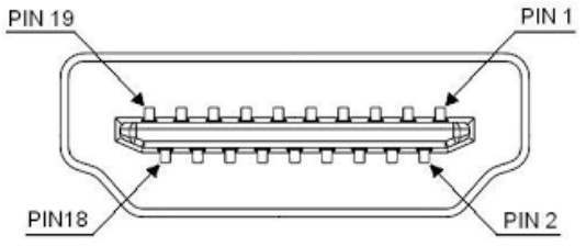
For versions of the firmware that support HDMI video the following table lists the connections to the standard HDMI Type A socket. The HDMI output is automatically enabled at startup – there are no options that need to be set.
| HDMI Pin | Raspberry Pico Pin |
|---|---|
| 1 | Pin 21 (GP16) via a 220Ω resistor |
| 2 | Ground |
| 3 | Pin 22 (GP17) via a 220Ω resistor |
| 4 | Pin 24 (GP18) via a 220Ω resistor |
| 5 | Ground |
| 6 | Pin 25 (GP19 via a 220Ω resistor |
| 7 | Pin 16 (GP12) via a 220Ω resistor |
| 8 | Ground |
| 9 | Pin 17 (GP13) via a 220Ω resistor |
| 10 | Pin 19 (GP14) via a 220Ω resistor |
| 11 | Ground |
| 12 | Pin 20 (GP15) via a 220Ω resistor |
| 13 | |
| 14 | |
| 15 | |
| 16 | |
| 17 | Ground |
| 18 | +5V via Schottky barrier diode |
| 19 |
The HDMI signal pins are driven at a high frequency and for this reason care should be taken as follows:
- Keep the signal traces as short as possible.
- Make sure that all signal traces are the same length.
- The 220Ω resistor should preferably be a surface mount type.
To generate the DVI/HDMI signal the firmware needs to overclock the RP2350 to as high as 372MHz and most Raspberry Pi Pico 2 modules will not have any trouble at these speeds. However, this cannot be guaranteed, especially with third party modules. An example is the Pimoroni Pico Plus 2 which is marginal at the required speeds and therefore cannot be recommended with the HDMI versions of the PicoMite firmware.
Similar to how VGA is generated, the output of MMBasic is written to a framebuffer which, using the second CPU and DMA, is fed to the HSTX peripheral which in turn generates the parallel video data. The video signal produced is actually DVI (HDMI supports DVI) so this means that audio is not supported on the HDMI output and sophisticated HDMI features such as High Definition Content Protection (HDCP) and Ethernet are also not supported.
HDMI video supports a number of resolutions. To set these you use the following command:
OPTION RESOLUTION nn
Where nn is one of:
640x480or6401280x720or12801024x768or1024800x600or800720x400or720848x480or848
Each HDMI resolution can operate in a number of modes which are set using the MODE command. Note that
many modes reduce the displayed resolution to save memory for other features, this reduction is done by
doubling or quadrupling each pixel, however the monitor will always see the resolution (ie, pixel density) set
by the OPTION RESOLUTION command. The default is RESOLUTION 640x480 and MODE 1
Reference Designs
VGA/PS2 Reference Design (Raspberry Pi Pico)
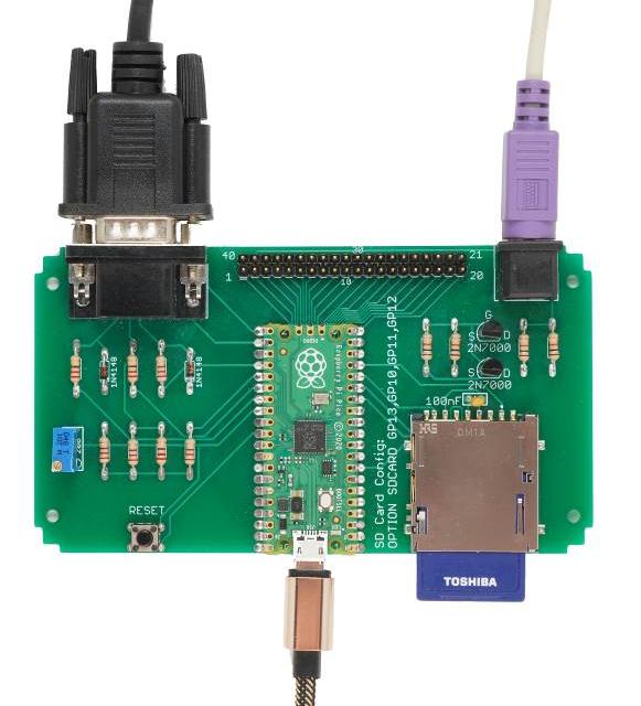
This is an easy to assemble design that implements the VGA output, PS2 keyboard interface and the SD Card socket (this design was featured in Silicon Chip magazine).
It uses common thru-hole components and can be assembled in under an hour.
All 40 pins on the Raspberry Pi Pico are routed to a 40-way connector on the rear of the PCB in the same configuration as that used by the Pico. This makes it easy to connect external devices as you can consult the pin out diagram in this manual and then select the corresponding pins on the 40-way connector.
Allowing for the I/O pins reserved for the VGA output, keyboard and SD Card there are 14 I/O pins available for external circuitry.
The board is sized to fit in an Altronics snap-together case 130 × 75 × 28mm (part number H0376).
The construction pack for this design can be downloaded from: https://geoffg.net/picomitevga.html (at the bottom of the page).
HDMI/USB Reference Design (Raspberry Pi Pico 2)
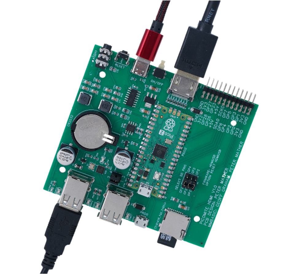
This is a full featured design based on the Raspberry Pi Pico 2 (using the RP2350 processors) which includes:
- HDMI video output
- Four USB interfaces for keyboard, mouse, game pad, etc.
- High quality audio output for amplified speakers.
- USB interface to the serial console.
- Battery backed real-time clock.
- Micro SD card socket.
- 14 I/O pins made available on the rear panel.
- Sized to fit a Multicomp MCRM2015S or Hammond RM2015S enclosure.
The construction pack for this design can be downloaded from https://geoffg.net/picomitevga.html (at the bottom of the page).
Keyboard/Mouse/Gamepad
The PicoMite firmware can accommodate a keyboard and mouse using either the PS2 or USB interfaces. The choice between PS2 and USB is determined by the version of the firmware loaded. See the chapter Firmware Versions and Files at the start of this manual.
USB versions of the firmware will also support a PS3 or PS4 gamepad with a USB interface. For versions without USB support the WII (CLASSIC) and WII NUNCHUCK commands can be used to specify a gamepad connected using I²C.
A keyboard can be used to input data to the BASIC program or, with a VGA/HDMI video output, be used to create a self contained computer with keyboard and display. Instead of using a video output you can also connected an LCD panel on versions supporting this and display the MMBasic console output on the LCD panel, creating a more compact version of a self contained computer. See the section LCD Display as the Console Output for details on how to do this.
PS2 Keyboard on the Raspberry Pi Pico (RP2040)
The PS2 keyboard clock and data signals operate at 5V but the I/O pins on the RP2040 processors must not be subjected to more than 3.6V. For this reason a level shifter should be employed so that the Raspberry Pi Pico sees signal voltages in the range 0 to 3.3V while the keyboard sees voltages 0 to 5V.
There are many ways that this can be accomplished but the following circuit is a simple and low cost solution:
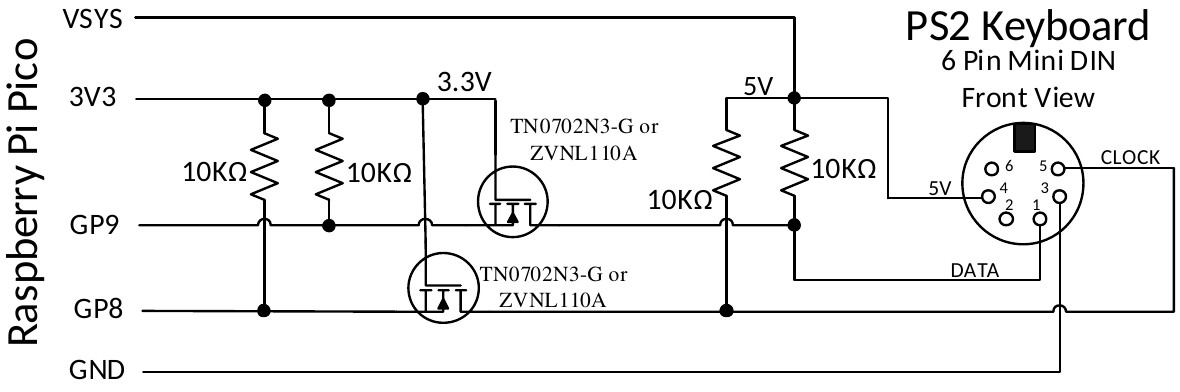
The recommended MOSFET is a TN0702N3-G or ZVNL110A however the commonly available 2N7000 has been tested and works well.
After it is connected the keyboard must be enabled with the OPTION KEYBOARD command.
PS2 Keyboard on the Raspberry Pi Pico 2 (RP2350)
The I/O pins on the RP2350 series of microcontrollers can withstand 5V (while powered up) so the keyboard
can be directly connected as illustrated with the 5V supplied by the VSYS pin on the Raspberry Pi Pico 2.
The keyboard is enabled with the OPTION KEYBOARD command.
PS2 Mouse
The I/O pins used for a PS2 mouse must be configured using the commands OPTION MOUSE (at the
command prompt) or MOUSE OPEN (within a program).
A PS2 mouse is powered via 5V so on a Raspberry Pi Pico (RP2040) a level shifter will be required for the mouse clock and data pins - this can be the same as the above circuit for a PS2 keyboard. On a Raspberry Pi Pico 2 (RP2350) a level shifter is not required so the mouse can be directly connected.
USB Interface
Versions of the firmware (both RP2040 or RP2350) with USB support will allow the connection of a keyboard, mouse and/or gamepad, all via the USB interface. To accomplish this the Raspberry Pi Pico’s USB port is converted to a USB host (as against its normal mode of USB client). This is possible because the Pico’s connector and electronics are USB OTG (On The Go) compliant similar to the connector on many mobile phones.
Because the USB connector is used for other duties the Pico must be powered via 5V applied to the VSYS pin or the VbUS pin if you desire to power an external hub/keyboard from the pico.
To connect a USB device you need a converter cable which has a Micro Male USB plug on one end (for the Pico) and a Type A USB socket at the other end (for the device). A typical example is the Jaycar Cat Nbr WC7725.
Because the USB interface on the Pico has been converted to a USB host you will not have access to the MMBasic serial console. The firmware accommodates this by automatically using pin 11 (GP8) for the serial console Tx and pin 12 (GP9) for Rx and setting the baudrate to 115200 baud. To access this console you will need a USB to serial bridge which provides a TTL serial interface on one side and a USB interface on the other (search for modules using the CP2102 or CH340 chip). If needed OPTION SERIAL CONSOLE can be used to change the pins used for the console.
USB Hub
The firmware will also support a USB hub via this interface so it is possible to have multiple keyboards or a
keyboard plus a mouse plus a gamepad, etc. A maximum of 4 devices may be connected via a hub. These are
reference by a channel index number (1 to 4). Use MM.INFO(USB n) to return the device code for any device
connected to channel n. By default a keyboard will be allocated to channel 1. A mouse will be allocated to
channel 2. The first gamepad will be allocated to channel 3 and a second gamepad to channel 4.
If you use a USB hub it is better to use an unpowered hub (ie, one that is powered by the Raspberry Pi Pico). This is because the USB protocol stack cannot reset the hub and it may be confused if the power on the Pico is cycled without doing the same for the hub. The hub can also be confused if devices are swapped while the hub is powered. If this happens you should cycle the power on the Pico followed by the hub then add the USB devices one by one.
Note that a hub is not required. If you only want to connect one device (for example a keyboard) you can just plug the device (using an adapter cable) directly into the Pico’s USB connector.
USB Keyboard
When a USB keyboard is connected it will be immediately recognised (no configuration required) and MMBasic will allocate it to channel 1 by default– there is nothing extra required.
USB Mouse
When a USB mouse is connected it will be immediately recognised (no configuration required) and MMBasic will allocate it to channel 2 by default– there is nothing extra required.
USB Gamepad

One or more PS3 or PS4 controllers or gamepad such as a Super Nintendo SNES Controller with a USB interface can be connected via USB (illustrated on the right).
By default the first gamepad will be allocated to channel 3 and a second
gamepad channel 4. Within a program the data from the gamepad can be read
using the DEVICE(GAMEPAD) function.
Configuring the Keyboard
By default the keyboard configuration will be assumed to be the standard US layout. However the OPTION KEYBOARD command can be used to configure layouts for other countries.
The syntax of the command is:
OPTION KEYBOARD language
Where language is a two-character code such as US for the standard keyboard used in the USA, Australia and
New Zealand. Other keyboard layouts are United Kingdom (UK), French (FR), German (GR), Belgium (BE),
Italian (IT) ), Brazilian (BR) or Spanish (ES).
Note that the non US layouts map some of the special keys present on these keyboards but the corresponding special character will not display as they are not part the standard PicoMite fonts. Instead a standard ASCII character will be used.
Using a Mouse
The mouse is especially useful in the MMBasic program editor where it can replicate much of the functionality found in GUI editors such as Notepad in Windows (see the heading Full Screen Editor above in this manual).
This includes positioning the insert point and copy and paste using the clipboard.
A mouse can also be used in a program where its position can be queried by using the DEVICE() function. As
an example, the following program will report any mouse movement.
Note that the mouse is always allocated to channel 2
‘ continuous loop to print on the console any movement
Do
    mx=DEVICE(MOUSE 2, x)
    my=DEVICE(MOUSE 2, y)
    If mx <> tx Or my <> ty Then Print mx, my
    tx = mx : ty = my
Loop
Program and Data Storage
The BASIC program is held in flash memory and is run from there. When a program is edited via EDIT or
loaded via the console it will be saved there. Flash memory is non-volatile so the program will not be lost if the
power is lost or the processors is reset.
In addition to this program memory there are three other locations where programs can be saved. These are described in detail below and are Flash Slots, the Flash Filesystem and an attached SD Card
Flash Slots There are three of these which can be used to save completely different programs or previous versions of the program you are working on (in case you need to revert to an earlier version). In addition, MMBasic will allow a BASIC program to load and run another program saved to a numbered flash location while retaining all the variables and settings of the original program – this is called chaining and allows for a much larger program to be run than the amount of program memory would normally allow.
To manage these numbered locations in flash you can use the following commands (note that in the following n
is a number from 1 to 3):
Command | Description
:-: | :-
FLASH SAVE n | Save the program in the program memory to the flash location n.
FLASH LOAD n | Load a program from flash location n into the program memory.
FLASH RUN n | Run a program from flash location n, clears all variables but does not erase or change the program held in the main program memory.
FLASH LIST | Display a list of all flash locations including the first line of the program.
FLASH LIST n [,ALL] | Lists the program held in location n. Use FLASH LIST n,ALL to list without page breaks
FLASH ERASE n | Erase flash location n.
FLASH ERASE ALL | Erase all flash locations.
FLASH CHAIN n | Run the program in flash location n, leaving all variables intact. This allows for very large programs, that can be split into two or three parts, to be run.
It does not erase or change the program held in the main program memory.
FLASH OVERWRITE n | Erase flash location n and then save the program in the program memory to that location.
FLASH DISK LOAD f$ [,O] | Loads a flash slot with a binary file created using LIBRARY DISK SAVE. Overwrites the slot if the optional O is specified.
In addition, the command OPTION AUTORUN can be used to specify a flash program location to be set running when power is applied or the CPU restarted. This option can also be used without specifying a flash location and in that case MMBasic will automatically run the program in program memory.
Notes:
- It is recommended that you include a comment describing the program as the first line of the program. This
will then be displayed by the
FLASH LISTcommand and will help identify the program. - All BASIC programs saved to flash may be erased if you upgrade (or downgrade) the PicoMite firmware. So make sure that you backup these first.
- The
LIBRARYcommand uses Slot 3 for saving library data therefore only 2 slots will be available if the library feature is used.
Flash Filesystem
This is an area of the Raspberry Pi Pico’s flash memory which is automatically created by the firmware and
will look like a normal disk drive to MMBasic. It is called drive A: and data and programs can be read/written
using the normal BASIC file commands (SAVE, RUN, OPEN, etc). In addition, sub directories can be created
and deleted and long filenames used.
For example, to run a program:
RUN "A:/MyProgram.bas"
Open a text file for random access:
OPEN "A:/data/database.dat" FOR RANDOM as #4
This drive is automatically created when the PicoMite firmware is loaded so it will always be available to the BASIC program. It can be used to store programs, images, music, configuration data, log files and much more. Its size varies depending on the amount of flash memory – on a Raspberry Pi Pico with 2MB flash it will be 200 to 500KB, on a Raspberry Pi Pico 2 with 4MB flash it will be a little over 2MB and on a module with 16MB the flash filesystem will be up to 14MB in size.
The system will create and maintain the file BOOTCOUNT on the Flash Filesystem. This keeps a count of
the number of times the device has been restarted and can be read with the function MM.INFO(boot count).
SD Cards
An SD card socket can be connected to the Raspberry Pi Pico and accessed as drive B:. Like the Flash Filesystem the normal BASIC file commands can be used to save/load programs as well as opening data files for read/write.
Cards up to 32 GB formatted in FAT16 or FAT32 are supported and the files created can also be read/written on personal computers running Windows, Linux or the Mac operating system. The PicoMite firmware uses the SPI protocol to talk to the card and this is not influenced by the card type, so all types (Class 4, 10, UHS-1 etc) are supported.
The SPI protocol needs to be specifically configured before it can be used. This can be done in one of two ways - by using the “system” SPI port or by directly specifying the I/O pins to use:
System SPI Port
This is a port that will be used for system use (SD card, LCD display and the touch controller on an LCD panel). There are a number of ports and pins that can be used (see the chapter PicoMite Hardware) but this example uses SPI on pins GP18, GP19 and GP16 for Clock, MOSI and MISO respectively.
OPTION SYSTEM SPI GP18, GP19, GP16
Then MMBasic must be told that there is an SD card attached and what pin is used for the Chip Select (CS) signal:
OPTION SDCARD GP22
Dedicated I/O Pins
Alternatively, where no other devices share the SPI bus with the SD card it can be set up with:
OPTION SDCARD CS_pin, CLK_pin, MOSI_pin, MISO_pin
In this case the pins can be assigned completely flexibly and do not need to be capable of SPI operation but SD card performance will be better if valid SPI pins are chosen.
These commands must be entered at the command prompt (not in a program) and will cause the PicoMite firmware to restart. This has the side effect of disconnecting the USB console interface which will need to be reconnected.
When the Raspberry Pi Pico is restarted MMBasic will automatically initialise the SD Card interface. This SPI
port will then not be available to BASIC programs (ie, it is reserved). To verify the configuration, you can use
the command OPTION LIST to list all options that have been set including the configuration of the SD Card.
The basic circuit diagram for connecting the SD Card connector using these pin allocations is illustrated below.
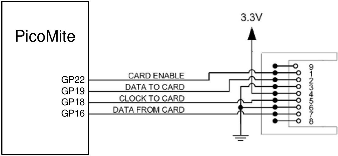
| Raspberry Pi Pico Pins | SD Card Pins | |
|---|---|---|
| unused | 9 | |
| GP22 | card enable | 1 |
| GP19 | data to card | 2 |
| GND | ground | 3 |
| 3V3 | 3.3V Power | 4 |
| GP18 | clock to card | 5 |
| GND | ground | 6 |
| GP16 | data from card | 7 |
| unused | 8 |
Note that you can use many different configurations using various pin allocations – this is just an example based on the configuration commands listed above.
Care must be taken when the SPI port is shared between a number of devices (SD Card, touch, etc). In this case all the Chip Select signals must configured in MMBasic or alternatively disabled by a permanent connection to 3.3V. If this is not done any floating Chip Select signal lines can cause the wrong controller to respond to commands on the SPI bus.
Combined Chip Select
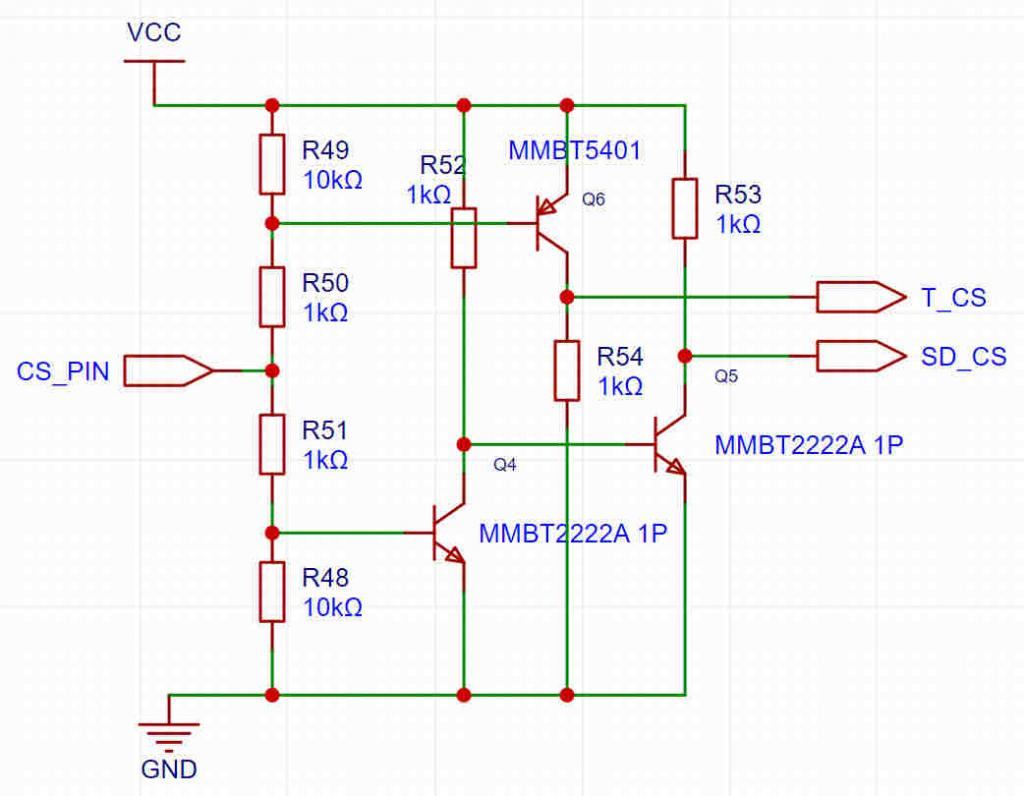
The chip select pin used for the SD card and the touch controller on an LCD panel can be combined by using the
OPTION SDCARD COMBINED CS command. If this is specified the following circuitry is required to
implement the SD chip select:
The firmware uses the touch pin as follows:
- TOUCH_CS low: TOUCH_CS low, SD_CS high
- TOUCH CS high: SD_CS low: TOUCH_CS high
- TOUCH CS set as input (high impedance) TOUCH_CS and SD_CS high.
MMBasic Support for Flash and SD Card Filesystems
The MMBasic support for the Flash Filesystem and SD Cards is almost identical. This allows programs to use either filesystem with minimal modification.
- The Flash Filesystem is referred to as drive
A: - while the SD Card (when connected) is drive
B:.
The default drive can be set with the DRIVE command and then the drive prefix is not needed.
In the following note that:
- Upper/lowercase characters and spaces are allowed. The file system on the SD Card is NOT case sensitive however the Flash Filesystem IS case sensitive (this is the only difference between the two).
- Long file/directory names are supported in addition to the old 8.3 format.
- The maximum file/path length is 63 characters.
- Any file path that uses the drive letter must be a full path from the root
- For example:
"A:/mypath/myfile.txt").
- For example:
- Directory paths are allowed in file/directory strings.
- For example:
OPEN "A:\dir1\dir2\file.txt" FOR …).
- For example:
- Either forward or back slashes can be used in paths.
- For example:
"\dir\file.txt"is the same as"/dir/file.txt".
- For example:
- On startup the active drive (ie, the default) is
A:(the Flash Filesystem). - The current PicoMite firmware time is used for file create and last access times.
- Up to ten files can be simultaneously open, mixed between the
A:andB:drives.
#fnbris the file number (1to10)- For example:
OPEN '3rdfile.txt' FOR OUTPUT AS #3
- For example:
- Except for
INPUT,LINE INPUTandPRINTthe#in#fnbris optional and may be omitted.
Programs can be loaded from or saved to the Flash Filesystem and SD Cards using these commands.
| Command | Description |
|---|---|
LOAD fname$ [,R] | Load a BASIC program. The optional suffix ,R will cause the program to be run after it has been loaded (in this case fname$ must be a string constant). |
RUN fname$ | Load a BASIC program and run it. fname$ can be a variable. |
SAVE fname$ | Save the current program to the Flash Filesystem or SD Card. |
These are the basic commands for reading and writing data.
| Command | Description |
|---|---|
OPEN fname$ FOR mode AS #fnbr | Opens a file for reading or writing. 'fname$' is the file name. 'mode' can be INPUT, OUTPUT, APPEND or RANDOM. ‘#fnbr’ is the file number ( 1 to 10). |
PRINT #fnbr, expression [[,; ]expression] … etc | Outputs text to the file opened as #fnbr. |
INPUT #fnbr, list of variables | Read a list of comma separated data into the variables specified from the file previously opened as #fnbr. |
LINE INPUT #fnbr, variable$ | Read a complete line into the string variable specified from the file previously opened as #fnbr. |
FLUSH #fnbr | Forces any buffered writes to be written to the Flash Filesystem or SD Card. It is recommended that this command be used regularly where data loss could occur in the event of power loss. |
CLOSE #fnbr [,#fnbr] … | Close the file(s) previously opened with the file number ‘#fnbr’. |
Basic file and directory manipulation. Most can be done at the command prompt or from within a BASIC program.
| Command | Description |
|---|---|
DRIVE drive$ | Sets the active disk drive as drive$. drive$ can be "A:" or "B:" where A is the flash drive and B is the SD Card (if configured). |
DRIVE "A:/FORMAT" | Reformat the Flash Filesystem (drive A:) to its initial state. |
FILES [wildcard] | Search the current directory and list the files/directories found. Note: Can only be used at the command prompt, not within a program. |
LIST fname$ | List the contents of a program or text file on the console. |
KILL fname$ | Delete a file in the current directory on the current drive. See the command reference for more details on wildcard deletes. |
MKDIR dname$ | Creates a sub directory in the current directory on the current drive. |
CHDIR dname$ | Change into to the directory $dname. $dname can also be ".." (dot dot) for up one directory or "\" for the root directory. The starting point is the current directory on the current drive. |
RMDIR dir$ | Remove, or delete, the directory dir$ in the current directory on the current drive. |
SEEK #fnbr, pos | Will position the read/write pointer in a file that has been opened for RANDOM access to the pos byte. |
RENAME fromname$ AS toname$ | Will rename the file fromname$ to have the name toname$ in the current directory on the current drive |
COPY [mode] fromname$ TO toname$ | Will copy the file fromname$ to have the file toname$. |
See the command reference for more details on the optional mode and wildcard copies.
Also there are a number of functions that support the above commands.
| Function | Description |
|---|---|
INPUT$(nbr, #fnbr) | Will return a string composed of ‘nbr’ characters read from a file previously opened for INPUT or RANDOM with the file number #fnbr. If less than ‘nbr’ characters are available the function will return with what it has (including an empty string if no characters are available). |
DIR$(fspec, type) | Will search for files and return the names of entries found. |
CWD$ | Will return the current working directory. |
EOF(#fnbr) | Will return true if the file previously opened for INPUT with the file number #fnbr is positioned at the end of the file. |
LOC(#fnbr) | For an open file this will return the current position of the read/write pointer in the file. |
LOF(#fnbr) | Will return the current length of the file in bytes. |
MM.INFO(drive) | Will return the current active drive – ie, "A:" or "B:" |
MM.INFO(free space) | Will return how much space is left on the active drive |
MM.INFO(disk size) | Will return the size of the active drive |
MM.INFO(exists file fname$) | Will return true if the file exists |
MM.INFO(exists dir dirname$) | Will return true if the directory exists |
MM.INFO(path) | Will return the file path of the program being run. This allows the user to create path relative references for any resource files needed in a program. |
See also the function reference for more details.
XModem Transfer
In addition to the standard method of XModem transfer which copies to or from the program memory the PicoMite firmware can also copy to and from a file on the Flash Filesystem or SD Card. The syntax is:
XMODEM SEND filename$
or
XMODEM RECEIVE filename$
Where ‘filename$’ is the file to save or send. ‘filename$’ can be a string expression, variable or constant. If it
is a constant the string must be quoted (eg,, XMODEM SEND "prbas.bas"). In the case of receiving a file, any
file with the same name will be overwritten.
Load and Save Image
An image can be loaded from the Flash Filesystem or SD Card for display on an attached LCD display panel or VGA/HDMI monitor. This can be used to draw a logo or add a background on the display.
The syntax is:
| Command | Description |
|---|---|
LOAD IMAGE filename$ [, StartX, StartY] | load a BMP bitmap image |
LOAD JPG filename$ [, StartX, StartY] | load a Jpeg image |
LOAD PNG filename$ [, StartX, StartY] | load a Png image (Pico2/RP2350 only) |
Where filename$ is the image to load and StartX/StartY are the coordinates of the top left corner of the image (these are optional and will default to the top left corner of the display if not specified).
The image must be in the appropriate format (BMP, JPG or PNG) and MMBasic will add the extension to the file name if it is not specified. All types of images are supported including black and white and true colour 24-bit images.
The current image on the video output, virtual LCD or an LCD panel that supports BLIT can be saved to a file using the following command:
SAVE IMAGE filename$ [,StartX, StartY, width, height]
This will save the image, or part of the image, as a 24-bit true colour BMP file (the extension .BMP) will be added if an extension is not supplied.
Example of Sequential I/O
In the example below a file is created and two lines are written to the file (using the PRINT command). The file is then closed.
OPEN "fox.txt" FOR OUTPUT AS #1
PRINT #1, "The quick brown fox"
PRINT #1, "jumps over the lazy dog"
CLOSE #1
You can read the contents of the file using the LINE INPUT command. For example:
OPEN "fox.txt" FOR INPUT AS #1
LINE INPUT #1,a$
LINE INPUT #1,b$
CLOSE #1
LINE INPUT reads one line at a time so the variable a$ will contain the text "The quick brown fox" and b$ will contain "jumps over the lazy dog".
Another way of reading from a file is to use the INPUT$() function. This will read a specified number of characters. For example:
OPEN "fox.txt" FOR INPUT AS #1
ta$ = INPUT$(12, #1)
tb$ = INPUT$(3, #1)
CLOSE #1
The first INPUT$() will read 12 characters from #1 and the second three characters. So the variable ta$ will contain The quick br and the variable tb$ will contain own.
Files normally contain just text and the print command will convert numbers to text. So in the following
example the first line will contain the line 123 and the second 56789.
nbr1 = 123 : nbr2 = 56789
OPEN "numbers.txt" FOR OUTPUT AS #1
PRINT #1, nbr1
PRINT #1, nbr2
CLOSE #1
You can read the contents of this file using the LINE INPUT command but then you would need to convert the
text to a number using VAL().
For example:
OPEN "numbers.txt" FOR INPUT AS #1
LINE INPUT #1, a$
LINE INPUT #1, b$
CLOSE #1
x = VAL(a$) : y = VAL(b$)
Following this the variable x would have the value 123 and y the value 56789.
Random File I/O
For random access the file should be opened with the keyword RANDOM. For example:
OPEN "filename" FOR RANDOM AS #1
To seek to a record within the file you would use the SEEK command which will position the read/write
pointer to a specific byte. The first byte in a file is numbered one so, for example, the fifth record in a file that
uses 64 byte records would start at byte 257. In that case you would use the following to point to it:
SEEK #1, 257
When reading from a random access file the INPUT$() function should be used as this will read a fixed number
of bytes (i.e. a complete record) from the file. For example, to read a record of 64 bytes you would use:
dat$ = INPUT$(64, #1)
When writing to the file a fixed record size should be used and this can be easily accomplished by adding sufficient padding characters (normally spaces) to the data to be written. For example:
PRINT #1, dat$ + SPACE$(64 – LEN(dat$));
The SPACE$() function is used to add enough spaces to ensure that the data written is an exact length (64 bytes
in this example). The semicolon at the end of the print command suppresses the addition of the carriage return
and line feed characters which would make the record longer than intended.
Two other functions can help when using random file access. The LOC() function will return the current byte
position of the read/write pointer and the LOF() function will return the total length of the file in bytes.
The following program demonstrates random file access. Using it you can append to the file (to add some data
in the first place) then read/write records using random record numbers. The first record in the file is record
number #1, the second is #2, etc.
RecLen = 64
OPEN "test.dat" FOR RANDOM AS #1
DO
    abort: PRINT
    PRINT "Number of records in the file =" LOF(#1)/RecLen
    INPUT "Command (r = read, w = write, a = append, q = quit): ", cmd$
    IF cmd$ = "q" THEN CLOSE #1 : END
    IF cmd$ = "a" THEN
        SEEK #1, LOF(#1) + 1
    ELSE
        INPUT "Record Number: ", nbr
    IF nbr < 1 or nbr > LOF(#1)/RecLen THEN PRINT "Invalid record" : GOTO abort
        SEEK #1, RecLen * (nbr - 1) + 1
    ENDIF
    IF cmd$ = "r" THEN
        PRINT "The record = " INPUT$(RecLen, #1)
    ELSE
        LINE INPUT "Enter the data to be written: ", dat$
        PRINT #1,dat$ + SPACE$(RecLen - LEN(dat$));
    ENDIF
LOOP
Random access can also be used on a normal text file. For example, this will print out a file backwards:
OPEN "file.txt" FOR RANDOM AS #1
FOR i = LOF(#1) TO 1 STEP -1
    SEEK #1, i
    PRINT INPUT$(1, #1);
NEXT i
CLOSE #1
Sound Output
The PicoMite firmware can play stereo WAV, FLAC, MP3 or MOD files located on the Flash Filesystem or
SD Card and generate precise sine waves using the PLAY command.
Note that the switching power regulator on the Raspberry Pi Pico can cause some noise on the audio output. This can be reduced by disabling the regulator and powering the module via an external linear regulator.
Pulse Width Modulated (PWM) Signal
The audio is created using PWM outputs so before the PLAY commands can be used the PWM output pins
must be allocated as audio outputs:
This is done using the OPTION AUDIO command as follows:
OPTION AUDIO PWM-A-PIN, PWM-B-PIN
This command should be entered at the command prompt and will be saved, so it only needs to be run once. Both pins must be on the same PWM channel with PWM-A-PIN the left audio channel and PWM-B-PIN the right.
For example:
OPTION AUDIO GP0, GP1
The audio signal is superimposed on a 44KHz square wave (called the carrier wave) as a pulse width modulated (PWM) signal. This means that a low pass filter is required to remove the carrier and recover the audio signal.
Filter Circuits
Most low cost amplified speakers (for a personal computer) will not respond to the carrier frequency so they will act as a low pass filter in themselves. Therefore, if you want to keep it simple, you can directly connect the PWM output to an amplified speaker’s input and a reasonable sound output should be achieved. However, the high level of the 44KHz carrier may cause problems for the amplifier (eg, overheating or distortion) so the following filter is recommended. This removes most of the carrier and delivers about 2V peak to peak (0.6V RMS) with reasonable fidelity up to 8KHz (more than enough for most amplified speakers):
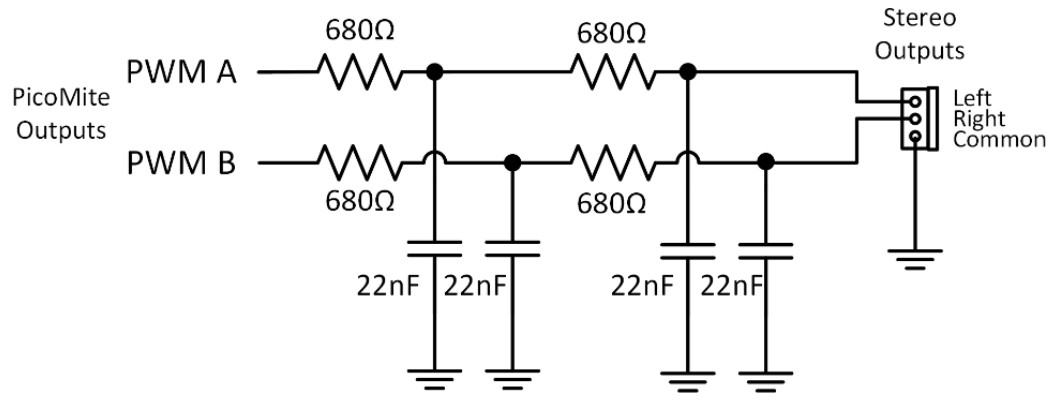
Below is a superior circuit producing quality audio with an insignificant amount of the carrier remaining. This is suitable for a more sophisticated HiFi amplifier/speaker configuration. The output is good for 10Hz to 15KHz at about 3V peak to peak (1V RMS) at 1KHz.
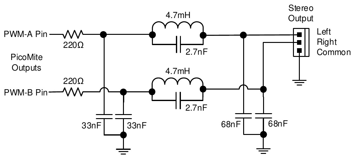
Both circuits are designed to feed an amplifier (not directly drive a headphone or speaker) and rely on capacitor coupling into the following amplifier (most have this).
VS1053 support
The audio output can be generated using a VS1053 CODEC module which is configured using the command
OPTION AUDIO VS1053 CLKpin, MOSIpin, MISOpin, XCSpin, XDCSpin, DREQpin,XRSTpin
This requires no output filtering and can drive 32Ω headphones direct. It also supports additional playback capabilities.
If a VS1053 codec is used as the audio output device, additional commands are available:
PLAY MP3 file$, interrupt
PLAY MIDIFILE file$, interrupt
PLAY MIDI
PLAY MIDI CMD cmd%, data1% [,data2%]
PLAY NOTE ON channel, note, velocity
PLAY NOTE OFF channel, note [,velocity]
PLAY HALT
PLAY CONTINUE track$
PLAY STREAM buffer%(), readpointer%, writepointer%
These are explained in more detail in the commands listing section.
MCP48n2 DAC
The audio output can also be generated through a connected MCP48n2 DAC (eg, MCP4822) in which case it is configured using the command:
OPTION AUDIO SPI CS-PIN, CLK-PIN, MOSI-PIN
The DAC does not need a complex low pass filter and a 120Ω resistor connected to the DAC output with the other end of the resistor connected to GND via a 100nF capacitor will be adequate. When a MCP4822 is used the LDAC pin on the DAC should be connected to GND.
I2S DAC
The audio output can also be generated though an I2S DAC such as the PCM5102A. The DAC must support creating its own master clock as this is not created by the firmware. The I2S DAC on the Pico2 (RP2350A/B) uses PIO2 to generate the output so this will not be available when the I2S DAC is enabled. The I2S DAC on the RP2040 uses PIO 0 which is shared with the VGA PIO on VGA versions.
The I2S DAC is configured with the command:
OPTION AUDIO I2S BCLK-PIN, DIN-PIN
The I2S word clock (LRCK) will then be on the next pin to the BCLK. So, for example if BCLK is set to GP0 then LRCK will be on GP1. Both these pins and the DIN pin must be unused when the command is issued. Typically, the DAC module will also require a GND and power pin to be connected (typically 5V) The I2S DAC will produce CD quality audio from FLAC files and output from MP3 files limited only by the inherent MP3 compression. FLAC files up to 96000Hz and 24-bit have been tested.
Playing WAV, FLAC, MP3 and MOD Files
The PLAY command can play a WAV, FLAC, MP3 (RP2350 only) or MOD file residing on the Flash Filesystem or SD Card to the sound output. It can be used to provide background music, add sound effects to programs and provide informative announcements.
The commands are:
PLAY WAV file$, interrupt
PLAY FLAC file$, interrupt
PLAY MODFILE file$, interrupt
PLAY MP3 file$, interrupt ‘RP2350 only
‘file$’ is the name of the audio file to play. It must be on the Flash Filesystem or SD Card and the appropriate extension (eg .WAV) will be appended if missing. The audio will play in the background (ie, the program will continue without pause). ‘interrupt’ is optional and is the name of a subroutine which will be called when the file has finished playing.
Generating Sine Waves
The PLAY TONE command uses the audio output to generate sine waves with selectable frequencies for the left and right channels. This feature is intended for generating attention catching sounds but, because the frequency is very accurate, it can be used for many other applications. For example, signalling DTMF tones down a telephone line or testing the frequency response of loudspeakers.
The syntax of the command is:
PLAY TONE left, right, duration, interrupt
‘left’ and ‘right’ are the frequencies in Hz to use for the left and right channels.
The tone plays in the background (the program will continue running after this command) and ‘duration’ specifies the number of milliseconds that the tone will sound for. ‘duration’ is optional and if not specified the tone will continue until explicitly stopped or the program terminates. ‘interrupt’ (if specified) will be triggered when the duration has finished.
The specified frequency can be from 1 Hz to 20 KHz and is very accurate (it is based on a crystal oscillator). The frequency can be changed at any time by issuing a new PLAY TONE command.
Using PLAY
It is important to realise that the PLAY command will generate the audio in the background. This allows a
program (for example) to play the sound of a bell while continuing with its control function. Without the
background facility the whole BASIC program would freeze while the sound was played.
However, generating the audio in the background has some subtle inferences which can trip up newcomers.
For example, take the following program:
PLAY TONE 500, 500, 2000
END
You may expect the 500Hz tone to sound for 2 seconds but in practice it will not make any sound at all. This is because MMBasic will execute the PLAY TONE command (which will start generating the sound in the background) and then it will immediately execute the END command which will terminate the program and the background sound. This will happen so fast that nothing is heard.
Similarly the following program will not work either:
PLAY TONE 500, 500, 2000
PLAY TONE 300, 300, 5000
This is because the first command will set a 500Hz the tone playing but then the second PLAY command will
immediately replace that with a 300Hz tone and following that the program will run off the end terminating the
program (and the background audio), resulting in nothing being heard.
If you want MMBasic to wait while the PLAY command is doing its thing you should use suitable PAUSE
commands. For example:
PLAY TONE 500, 500 : PAUSE 2000
PLAY TONE 300, 300 : PAUSE 5000
PLAY STOP
This applies to all versions of the PLAY command including PLAY WAV.
Utility Commands
There are a number of commands that can be used to manage the sound output:
| Command | Description |
|---|---|
| PLAY PAUSE | Temporarily halt (pause) the currently playing file or tone. |
| PLAY RESUME | Resume playing a file or tone that was previously paused. |
| PLAY NEXT | Play the next WAV, MP3 or FLAC file in a directory |
| PLAY PREVIOUS | Play the previous WAV, MP3, or FLAC file in a directory |
| PLAY STOP | Terminate the playing of the file or tone, same as when the program ends. |
| PLAY VOLUME L, R | Set the volume to between 0 and 100 with 100 being the maximum volume. The volume will reset to the maximum level when a program is run. A logarithmic scale is used so that PLAY VOLUME 50,50 should sound half as loud as 100,100. |
Specialised Audio Output
The PLAY SOUND command will generate an output based on a mixture of sine, square, etc waveforms. See
the details in the command listing.
Using the I/O pins
The Raspberry Pi Pico has 26 input/output pins which can be controlled from within the BASIC program with 3 of these supporting a high speed ADC (Analog to Digital Converter).
An I/O pin is referred to by its pin number and this can be the number (eg,, 2) or its GP number (eg,, GP1).
Digital Inputs
A digital input is the simplest type of input configuration. If the input voltage is higher than 2.5V the logic level will be true (numeric value of 1) and anything below 0.65V will be false (numeric value of 0). The inputs use a Schmitt trigger input so anything in between these levels will retain the previous logic level.
Note that the maximum voltage on the RP2040 (ie, the Raspberry Pi Pico) I/O pins is 3.3V. Level shifting will be required if a device uses 5V levels for signalling. The Raspberry Pi Pico 2 using the RP2350 can tolerate 5V (while powered) so, in this case, level shifting is not required for signals up to 5V.
In your BASIC program you would set the input as a digital input and use the PIN() function to get its level.
For example:
SETPIN GP4, DIN
IF PIN(GP4) = 1 THEN PRINT "High"
The SETPIN command configures pin GP4 as a digital input and the PIN() function will return the value of that
pin (the number 1 if the pin is high). The IF command will then execute the command after the THEN
statement if the input was high. If the input pin was low the program would just continue with the next line in
the program.
The SETPIN command also recognises a couple of options that will connect an internal resistor from the input
to either the supply or ground. This is called a "pullup" or "pulldown" resistor and is handy when connecting to
a switch as it saves having to install an external resistor to place a voltage across the contacts. Due to a
hardware issue with the RP2350 processor it is recommended that an external resistor of 8,2K or less be used if
a pulldown is required on that processor.
Analog Inputs
Pins marked as ADC can be configured to measure the voltage on the pin. The input range is from zero to 3.3V
and the PIN() function will return the voltage. For example:
> SETPIN 31, AIN
> PRINT PIN(31)
2.345
>
You will need a voltage divider if you want to measure voltages greater than 3.3V. For small voltages you may need an amplifier to bring the input voltage into a reasonable range for measurement.
The measurement uses 3.3V power supply to the CPU as its reference and it is assumed that this is exactly
3.3V. This value can be changed with the OPTION VCC command. In order to get the best possible reading,
the analogue input is sampled 10 times. The values are then sorted and the top 2 and bottom 2 discarded and the
remaining 6 averaged.
If you want the direct reading from the ADC you can use the raw mode by using the ARAW option to the SETPIN command:
SETPIN pinno,ARAW
In this case a value between 0 and 4095 will be returned based on a single sample.
The ADC commands provide an alternate method of recording analog inputs and are intended for high speed recording of many readings into an array.
Counting Inputs
Any four pins can be used as counting inputs to measure frequency, period or just count pulses on the input.
The pins used for this function can be configured using the OPTION COUNT command but, if not changed,
will default to GP6, GP7, GP8 and GP9.
As an example, the following will print the frequency of the signal on pin GP7:
> SETPIN GP7, FIN
> PRINT PIN(GP7)
110374
>
In this case the frequency is 110.374 kHz.
By default the gate time is one second which is the length of time that MMBasic will use to count the number
of cycles on the input and this means that the reading is updated once a second with a resolution of 1 Hz. By
specifying a third argument to the SETPIN command it is possible to specify an alternative gate time between
10 ms and 100000 ms. Shorter times will result in the readings being updated more frequently but the value
returned will have a lower resolution. The PIN() function will always scale the returned number as the
frequency in Hz regardless of the gate time used.
For example, the following will set the gate time to 10ms with a corresponding loss of resolution:
> SETPIN GP7, FIN, 10
> PRINT PIN(GP7)
110300
>
For accurate measurement of signals less than 10 Hz it is generally better to measure the period of the signal.
When set to this mode the PicoMite firmware will measure the number of milliseconds between sequential rising edges of the input signal. The value is updated on the low to high transition so if your signal has a period of (say) 100 seconds you should be prepared to wait that amount of time before the PIN() function will return
an updated value.
The count pins can also count the number of pulses on their input. When a pin is configured as a counter (for
example, SETPIN 7,CIN) the counter will be reset to zero and PicoMite firmware will then count every
transition from a low to high voltage. The counter can be reset to zero again by executing PIN(7) = 0.
Counting inputs are accurate up to about 200KHz at the default processors frequency. A minimum pulse width
of about 40nS is needed to trigger the counter. The RP2350 also has the option of configuring GP1 as an
extremely fast frequency counting pin (see the SETPIN GP1, FFIN command).
Digital Outputs
All I/O pins can be configured as a digital output using the DOUT parameter to the SETPIN command. For
example:
SETPIN GP15, DOUT
This means that when an output pin is set to logic low it will pull its output to zero and when set high it will pull its output to 3.3V. In MMBasic this is done with the PIN command. For example PIN(GP15) = 0 will set pin GP15 to low while PIN(GP15) = 1 will set it high.
Pulse Width Modulation
The PWM (Pulse Width Modulation) command allows the PicoMite firmware to generate square waves with a program controlled duty cycle.
By varying the duty cycle you can generate a program controlled voltage output for use in controlling external devices that require an analog input (power supplies, motor controllers, etc). The PWM outputs are also useful for driving servos and for generating a sound output via a small transducer.
RP2040 The PWM outputs consists of up to 8 channels (numbered 0 to 7) with each channel having two outputs (A and B). For each channel the frequency can be selected and for each output a different duty cycle can be set. Up to 16 pins can be configured as PWM outputs using the SETPIN command.
RP2350 The RP2350 supports up to 12 PWM channels numbered 0 to 11) and up to 24 pins can be configured as PWM outputs using the SETPIN command.
Communications Interfaces (Serial, SPI and I²C)
These are described in the appendices at the rear of this manual. Before these interfaces can be used the pins that are to be used for the relevant signals must be configured using the SETPIN command.
Some devices such as an SD Card, LCD panels, touch, etc also use SPI or I²C interfaces and the pins used for these must similarly be configured using the OPTION SYSTEM command before they can be used.
Interrupts
Interrupts are a handy way of dealing with an event that can occur at an unpredictable time. An example is when the user presses a button. In your program you could insert code after each statement to check to see if the button has been pressed but an interrupt makes for a cleaner and more readable program.
When an interrupt occurs MMBasic will execute a defined subroutine and when finished return to the main program. The main program is completely unaware of the interrupt and will carry on as normal.
Any I/O pin that can be used as a digital input can be configured to generate an interrupt using the SETPIN command with up to ten interrupts active at any one time. Interrupts can be set up to occur on a rising or falling digital input signal (or both) and will cause an immediate branch to the specified user defined subroutine. The target can be the same or different for each interrupt. Return from an interrupt is via the END SUB or EXIT SUB commands. Note that no parameters can be passed to the subroutine however within the interrupt calls to other subroutines and functions are allowed.
If two or more interrupts occur at the same time they will be processed in order of the interrupts as defined below. During the processing of an interrupt all other interrupts are disabled until the interrupt subroutine returns. During an interrupt (and at all times) the value of the interrupt pin can be accessed using the PIN() function.
Interrupts can occur at any time but they are disabled during INPUT statements. Also interrupts are not
recognised during some long hardware related operations (eg, the TEMPR() function, LCD drawing
commands, and SD access commands) although they will be recognised if they are still present when the
operation has finished. When using interrupts the main program is completely unaffected by the interrupt
activity unless a variable used by the main program is changed during the interrupt.
Because interrupts run in the background they can cause difficult to diagnose bugs. Keep in mind the following factors when using interrupts:
-
Interrupts are only checked by MMBasic at the completion of each command, and they are not latched by the hardware. This means that an interrupt that lasts for a short time can be missed, especially when the program is executing commands that take some time to execute. Most commands will execute in under 15µs however some commands such as the
TEMPR()function can take up to 200ms so it is possible for an interrupt to occur and vanish within this window and thus not be recognised. -
When inside an interrupt all other interrupts are blocked so your interrupts should be short and exit as soon as possible. For example, never use
PAUSEinside an interrupt. If you have some lengthy processing to do you should simply set a flag and immediately exit the interrupt, then your main program loop can detect the flag and do whatever is required. -
The subroutine that the interrupt calls (and any other subroutines or functions called by it) should always be exclusive to the interrupt. If you must call a subroutine that is also used by an interrupt you must disable the interrupt first (you can reinstate it after you have finished with the subroutine).
-
+Remember to disable an interrupt when you have finished needing it – background interrupts can cause strange and non-intuitive bugs.
In addition to interrupts generated by the change in state of an I/O pin, an interrupt can also be generated by other sections of MMBasic including timers and communications ports and the above notes also apply to them. The list of all these interrupts (in high to low priority ranking) is:
- PID control loops
- ON KEY individual
- ON KEY general
- ON PS2
- PIO RX FIFO
- PIO TX FIFO
- PIO RX DMA completion
- PIO TX DMA completion
- GUI Int Down
- GUI Int Up
- Sprite collision
- WebMite: TCP receive
- WebMite: MQTT compete
- WebMite: UDP receive
- USB Game Controller/USB or PS2 Mouse/Wii controller
- ADC completion
- I²C Slave Rx
- I²C Slave Tx
- I²C2 Slave Rx
- I²C2 Slave Tx
- WAV Finished
- COM1: Serial Port
- COM2: Serial Port
- IR Receive
- Keypad
- Interrupt command/CSub Interrupt
- I/O Pin Interrupts in order of definition
- Tick Interrupts (1 to 4 in that order)
As an example: If an ON KEY interrupt occurred at the same time as a COM1: interrupt the ON KEY interrupt
subroutine would be executed first and then, when the interrupt subroutine finished, the COM1: interrupt
subroutine would then be executed.
Special Device Support
To make it easier for a program to interact with the external world the PicoMite firmware includes drivers for a number of common peripheral devices.
These are:
- Infrared remote control
- DS18B20 temperature sensor
- DHT22 temperature/humidity sensor
- LCD display modules
- Numeric keypads
- Battery backed clock
- Ultrasonic distance sensor
- WS2812 RGB LEDs
- OV7670 Camera module: see the CAMERA command
Infrared Remote Control Decoder
You can easily add a remote control to your project using the IR command. When enabled this function will run in the background and interrupt the running program whenever a key is pressed on the IR remote control.
It will work with any NEC (see this pdf) or Sony compatible remote controls including ones that generate extended IR Receiver messages. Most cheap programmable remote controls will generate either protocol and using one of these you 3.3V can add a sophisticated flair to your Pico based project.
The NEC protocol is also used by many other PicoMite manufacturers including Apple, Pioneer, Sanyo, Akai and Toshiba so their branded remotes can be used.
To detect the IR signal you need an IR receiver. NEC remotes use a 38kHz modulation of the IR signal and suitable receivers tuned to this frequency include the Vishay TSOP4838, Jaycar ZD1952 and Altronics Z1611A. Note that the I/O pins on the Raspberry Pi Pico are only 3.3V tolerant and so the receiver must be powered by a maximum of 3.3V. The Raspberry Pi Pico 2 is different and can withstand 5V.
Sony remotes use a 40 kHz modulation but receivers for this frequency can be hard to find. Generally 38 kHz receivers will work but maximum sensitivity will be achieved with a 40 kHz receiver.
The IR receiver can be connected to any pin on the Raspberry Pi Pico. This pin must be configured by the program using the command SETPIN n, IR where n is the I/O pin to use for this function.
To setup the decoder you use the command IR dev, key, interrupt. Where dev is a variable that will be updated with the device code and key is the variable to be updated with the key code. interrupt is the interrupt subroutine to call when a new key press has been detected. The IR decoding is done in the background and the program will continue after this command without interruption.
This is an example of using the IR decoder connected to the GP6 pin:
SETPIN GP6, IR               ' define the pin to be used
DIM INTEGER DevCode, KeyCode ' variables used by the decoder
IR DevCode, KeyCode, IRInt   ' start the IR decoder
DO
  ' < body of the program >
LOOP

SUB IRInt                    ' a key press has been detected
  PRINT "Received device = " DevCode " key = " KeyCode
END SUB
IR remote controls can address many different devices (VCR, TV, etc) so the program would normally examine the device code first to determine if the signal was intended for the program and, if it was, then take action based on the key pressed. There are many different devices and key codes so the best method of determining what codes your remote generates is to use the above program to discover the codes.
more complex example
https://www.ad-notam.com/download/RS232/ad_notam_IR_protocol_DFU.pdf
Infrared Remote Control Transmitter
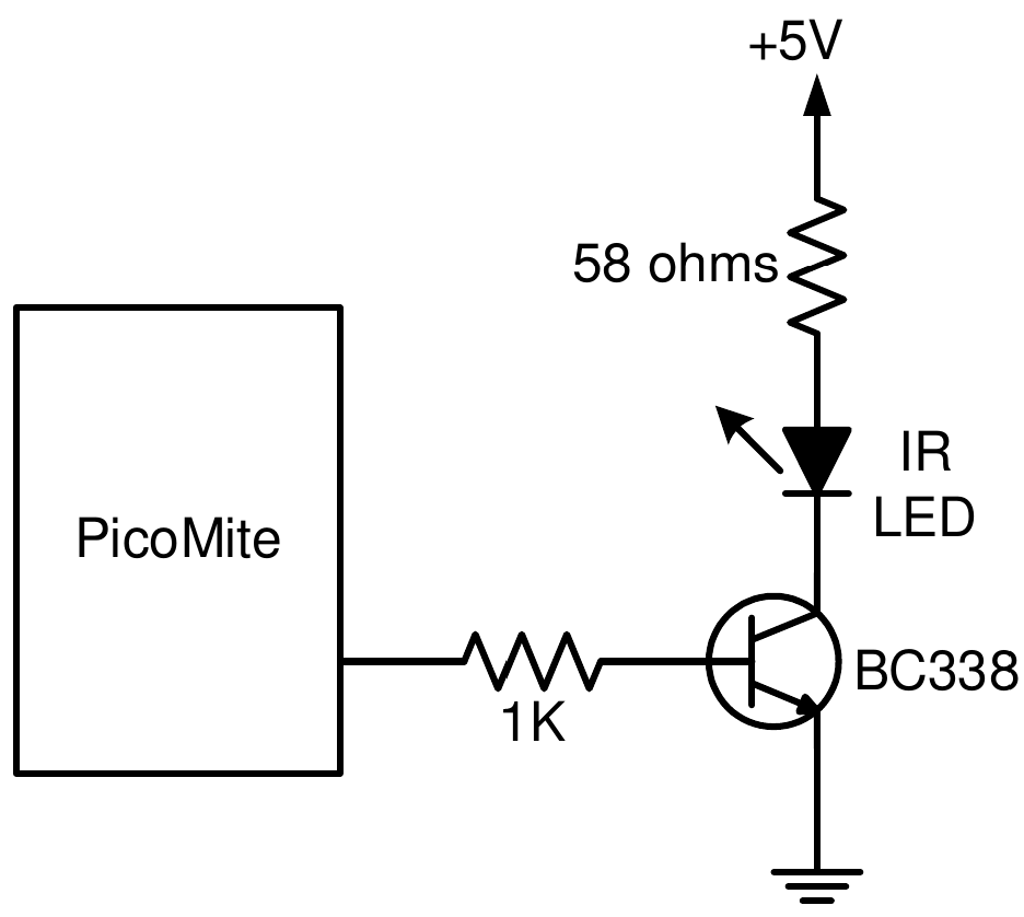
Using the IR SEND command you can transmit a 12 bit Sony infrared remote control signal. This is intended for Raspberry Pi Pico to Raspberry Pi Pico or Micromite communications but it will also work with Sony equipment that uses 12 bit codes. Note that all Sony products require that the message be sent three times with a 26 ms delay between each message.
The circuit on the right illustrates what is required. The transistor is used to drive the infrared LED because the output capability of the Raspberry Pi Pico is limited. This circuit provides about 50 mA to the LED.
To send a signal you use the command IR SEND pin, dev, key
Where pin is the I/O pin used, dev is the device code to send and key is the key code. Any I/O pin on the Raspberry Pi Pico can be used and you do not have to set it up beforehand (IR SEND will automatically do that).
The modulation frequency used is 38 kHz and this matches the common IR receivers (described in the previous page) for maximum sensitivity when communicating between two Raspberry Pi Picos or with a Micromite.
Measuring Temperature
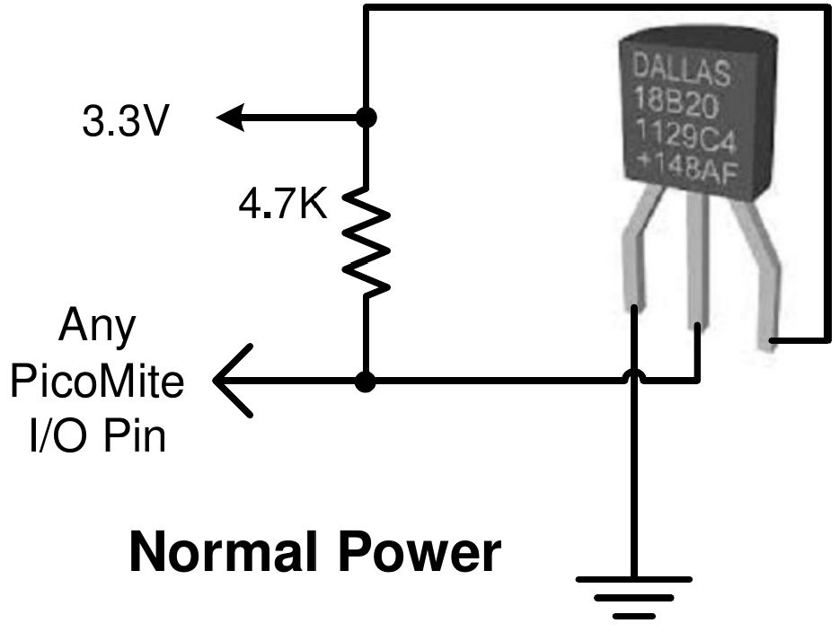
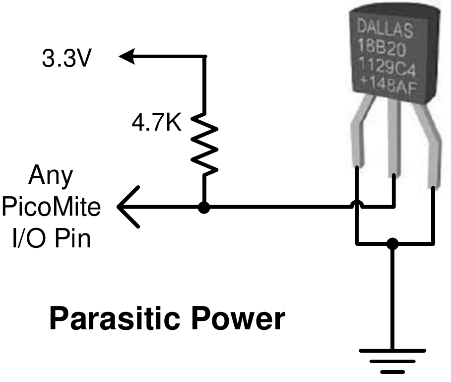
The TEMPR() function will get the temperature from a DS18B20 3.3V temperature sensor. This device can be purchased on eBay for about 4.7K US$5 in a variety of packages including a waterproof probe version.
The DS18B20 can be powered separately by a 3.3V supply or it can Any PicoMite operate on parasitic power from the Raspberry Pi Pico as shown on the I/O Pin right. Multiple sensors can be used but a separate I/O pin and a 4.7K pullup resistor is required for each one.
Normal Power To get the current temperature you just use the TEMPR() function in an expression. For example, PRINT "Temperature: " TEMPR(pin)
Where pin is the I/O pin to which the sensor is connected. You do not have to configure the I/O pin, that is handled by MMBasic.
3.3V The returned value is in degrees C with a resolution of 0.25 ºC and is 4.7K accurate to ±0.5 ºC. If there is an error during the measurement the returned value will be 1000.
Any PicoMite The time required for the overall measurement is 200ms and the running I/O Pin program will halt for this period while the measurement is being made.
This also means that interrupts will be disabled for this period. If you do Parasitic Power not want this you can separately trigger the conversion using the TEMPR START command then later use the TEMPR() function to retrieve the temperature reading. The TEMPR() function will always wait if the sensor is still making the measurement.
For example:
TEMPR START GP15
< do other tasks >
PRINT "Temperature: " TEMPR(GP15)
The TEMPR START command can also be used to change the resolution of the measurement (from the default 0.25 ºC) and the associated conversion time.
Measuring Humidity and Temperature
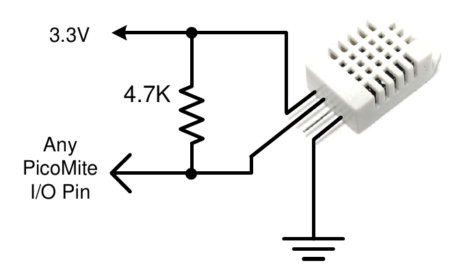
The HUMID command will read the humidity and temperature from a DHT22 humidity/temperature sensor. This device is also sold as the RHT03 or AM2302 but all are compatible and can be purchased on eBay for under $5. The DHT11 sensor is also supported.
The DHT22 must be powered from 3.3V (or up to 5V with the Raspberry Pi Pico 2) and it should have a pullup resistor on the data line as shown. This is suitable for long cable runs (up to 20 meters) but for short runs the resistor can be omitted as the PicoMite firmware also provides an internal weak pullup.
To get the temperature or humidity you use the HUMID command with three arguments as follows: HUMID pin, tVar, hVar [,DHT11]
Where pin is the I/O pin to which the sensor is connected. The I/O pin will be automatically configured by MMBasic.
tVar is a floating point variable in which the temperature is returned and hVar is a second variable for the humidity. The temperature is returned as degrees C with a resolution of one decimal place (eg, 23.4) and the humidity is returned as a percentage relative humidity (eg, 54.3).
If the optional DHT11 parameter is set to 1 then the command will use device timings suitable for that device.
In this case the results will be returned with a resolution of 1 degree and 1% humidity This example demonstrates using the DHT22 to display the current temperature and humidity every second:
DIM FLOAT temp, humidity
DO
  HUMID GP15, temp, humidity
  PRINT "The temperature is" temp " and the humidity is" humidity
  PAUSE 1000
LOOP
LCD Display
for system display panels see the chapter on Display Panels
The LCD command will display text on a standard LCD module with the minimum of programming effort.
For detailed command reference, see the LCD Commands section.
This command will work with LCD modules that use the KS0066, HD44780 or SPLC780 controller chip and have 1, 2 or 4 lines. Typical displays include the LCD16X2 (futurlec.com), the Z7001 (altronics.com.au) and the QP5512 (jaycar.com.au). eBay is another good source where prices can range from $10 to $50.
To setup the display you use the DEVICE LCD INIT command LCD INIT d4, d5, d6, d7, rs, en
d4, d5, d6 and d7 are the numbers of the I/O pins that connect to inputs D4, D5, D6 and D7 on the LCD module (inputs D0 to D3 and R/W on the module should be connected to ground). rs is the pin connected to the register select input on the module (sometimes called CMD or DAT). en is the pin connected to the enable or chip select input on the module.
Any I/O pins on the Raspberry Pi Pico can be used and you do not have to set them up beforehand (the LCD command automatically does that for you). The following shows a typical set up.
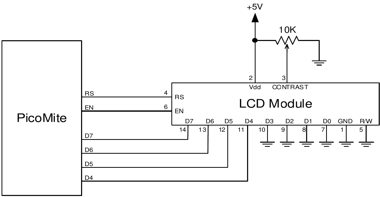
To display characters on the module you use the LCD command
LCD line, pos, data$
Where line is the line on the display (1 to 4) and pos is the position on the line where the data is to be written (the first position on the line is 1). data$ is a string containing the data to write to the LCD display.
The characters in data$ will overwrite whatever was on that part of the LCD.
The following shows a typical usage where d4 to d7 are connected to pins GP2 to GP5, rs is connected to pin GP6 and en to pin GP7.
LCD INIT GP2, GP3, GP4, GP5, GP6, GP7
LCD 1, 2, "Temperature"
LCD 2, 6, STR$(TEMPR(GP15)) ' DS18B20 connected to pin GP15
Note that this example also uses the TEMPR() function to get the temperature (described above).
Keypad Interface
A keypad is a low tech but effective method of entering numeric data. The PicoMite firmware supports either a 4x3 keypad or a 4x4 keypad and the monitoring and decoding of key presses is done in the background. When a key press is detected an interrupt will be issued where the program can deal with it.
Examples of a 4x3 keypad and a 4x4 keypad are the Altronics S5381 and S5383 (go to https://www.altronics.com ).
To enable the keypad feature you use the command KEYPAD var, int, r1, r2, r3, r4, c1, c2, c3, c4
Where var is a variable that will be updated with the key code and int is the name of the interrupt subroutine to call when a new key press has been detected. r1, r2, r3 and r4 are the pin numbers used for the four row connections to the keypad (see the diagram below) and c1, c2, c3 and c4 are the column connections. c4 is only used with 4x4 keypads and should be omitted if you are using a 4x3 keypad.
Any I/O pins on the Raspberry Pi Pico can be used and you do not have to set them up beforehand, the KEYPAD command will automatically do that for you.
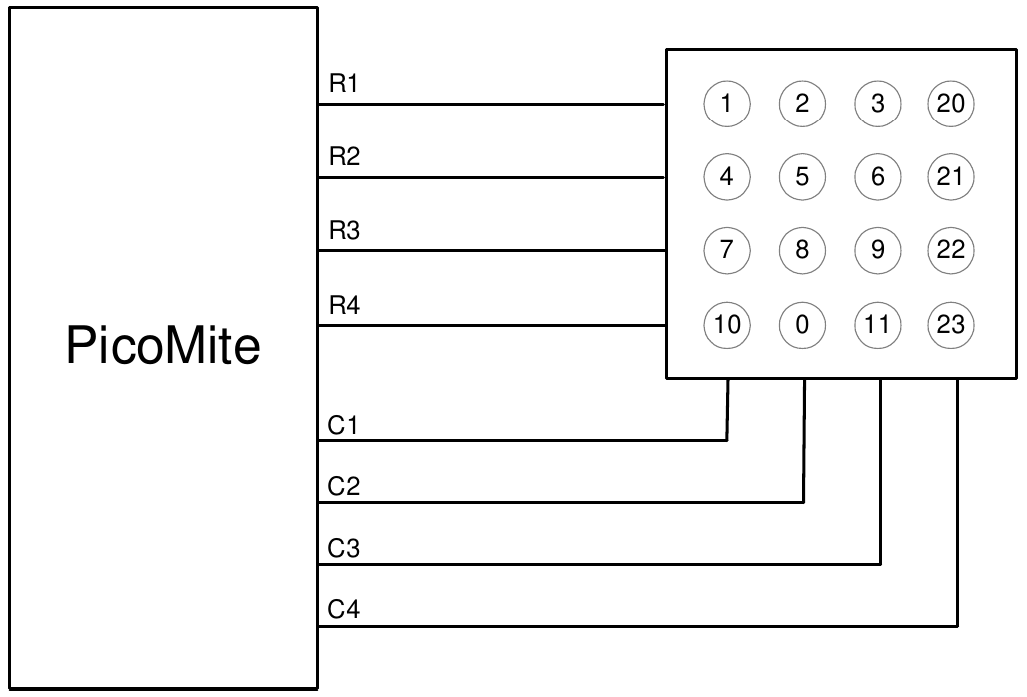
The detection and decoding of key presses is done in the background and the program will continue after this command without interruption. When a key press is detected the value of the variable var will be set to the number representing the key (this is the number inside the circles in the diagram above). Then the interrupt will be called.
For example:
Keypad KeyCode,KP_Int,GP2,GP3,GP4,GP5,GP6,GP7,GP8 ' 4x3 keybd
DO
< body of the program >
LOOP

SUB KP_Int           ' run when a key press has been detected
  PRINT "Key press = " KeyCode
END SUB
Real Time Clock Interface
Using the RTC GETTIME command it is easy to get the current time from a PCF8563, DS1307, DS3231 or DS3232 real time clock as well as compatible devices such as the M41T11. These integrated circuits are popular and cheap, will keep accurate time even with the power removed and can be purchased for US$2 to $8 on eBay. Complete modules including the battery can also be purchased on eBay for a little more.
The PCF8563 and DS1307 will keep time to within a minute or two over a month while the DS3231 and DS3232 are particularly precise and will remain accurate to within a minute over a year.
These chips are I²C devices and should be connected to the I²C I/O pins of the Raspberry Pi Pico.
Internal pullup resistors (100KΩ) are applied to the I²C I/O pins so, in many cases external resistors are not needed.
In order to enable the RTC you first need to allocate the I²C pins to be used using the command OPTION SYSTEM I2C SDApin, SCLpin
The time used by the RTC must also be set. That is done with the RTC SETTIME command which uses the format RTC SETTIME year, month, day, hour, minute, second (Note that the hour must be in 24 hour format).
For example, the following will set the real time clock to 4PM on the 10th November 2025:
RTC SETTIME 2025, 11, 10, 16, 0, 0
To get the time you use the RTC GETTIME command which will read the time from the real time clock chip and set the clock inside the Raspberry Pi Pico. Normally this command will be placed at the beginning of the program or in the subroutine MM.STARTUP so that the time is set on power up.
The command OPTION RTC AUTO ENABLE can also be used to set an automatic update of the TIME$ and DATE$ read only variables from the real time clock chip on boot and every hour.
Measuring Distance
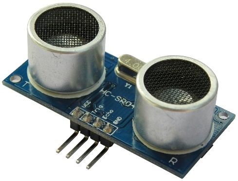
Using a HC-SR04 ultrasonic sensor and the DISTANCE() function you can measure the distance to a target.
This device can be found on eBay for about US$4 and it will measure the distance to a target from 3cm to 3m. It works by sending an ultrasonic sound pulse and measuring the time it takes for the echo to be returned.
Compatible sensors are the SRF05, SRF06, Parallax PING and the DYPME007 (which is waterproof and therefore good for monitoring the level of a water tank). Others that have been reported as working well use the CS100 chip - such as the HC-SR04 and US-025.
In the PicoMite firmware you use the DISTANCE function as follows:
d = DISTANCE(trig, echo)
The value returned is the distance in centimetres to the target.
Where trig is the I/O pin connected to the "trig" input of the sensor and echo is the pin connected the "echo" output of the sensor. You can also use 3-pin devices and in that case only one pin number is specified.
Note that the maximum voltage on all the Raspberry Pi Pico’s I/O pins is 3.3V. Level shifting will be required for this sensor because it uses 5V levels for its echo output. The Raspberry Pi Pico 2 can tolerate 5V (while powered) so, in this case, level shifting is not required.
WS2812 multicolour LED
The PicoMite firmware has built in support for the WS2812 multicolour LED chip. This chip needs a very specific timing to work properly and with the DEVICE WS2812 command it is easy to control these devices with minimal effort.
This command will output the required signals needed to drive a chain of WS2812 LED chips connected to the pin specified and set the colours of each LED in the chain. The syntax of the command is:
WS2812 type, pin, nbr%, colours%[()]
Note that the pin must be set to a digital output before this command is used. The colours%() array should be sized to have at least the same number of elements as the number of LEDs to be driven (nbr%). Each element in the array should contain the colour in the normal RGB888 format (0 - HFFFFFF). Where a single LED is to be driven then colours% should be a simple variable.
Up to 256 WS2812 chips in a string are supported.
type is a single character specifying the type of chip being driven as follows:
O= original WS2812B= WS2812BS= SK6812W= SK6812W (RGBW)
As an example:
DIM b%(4)=(RGB(red), Rgb(green), RGB(blue), RGB(Yellow), rgb(cyan))
SETPIN GP5, DOUT
WS2812 O, GP5, 5, b%()
will output the specified colours to an array of five WS2812 LEDs daisy chained off pin GP5.
It is possible that a WS2812 will not work reliably with the 3.3V output from the Raspberry Pi Pico. In this case there are a number of solutions:
- Use the WS2812B which will work with a 3.3V supply and inputs.
- Use the Raspberry Pi Pico 2 which can tolerate 5V (while powered) so, in this case, level shifting is not required..
- Use a single WS2812 powered from 3.3V as a first stage to buffer the input of the first "real" LED in the string.
The minimum supply for the WS2812 is 4V but in many cases it will work at 3.3V.
OV7670 Camera module
The PicoMite firmware has support for a OV7670 camera module. See the CAMERA command for details
Display Panels
NOT AVAILABLE ON HDMI OR VGA VERSIONS
The PicoMite firmware includes support for many LCD display panels using an SPI, I2C or parallel interface. These commands must be entered at the command prompt (not in a program) and will cause the PicoMite firmware to restart. This has the side effect of disconnecting the USB console interface which will need to be reconnected.
Note that the maximum voltage on all the Raspberry Pi Pico’s I/O pins is 3.3V. Level shifting will be required for displays that use 5V levels for signalling. The Raspberry Pi Pico 2 can tolerate 5V (while powered) so, in this case, level shifting is not required.
System SPI Bus
The system SPI bus is a dedicated SPI channel which is used by many LCD panels, all touch controllers and also to communicate with a SD Card. If any of these are attached the I/O pins used for the system SPI bus must be defined first.
This is done using this command:
OPTION SYSTEM SPI CLK-pin, MOSI-pin, MISO-pin
This must be entered at the command prompt and will cause the firmware to restart and disconnect the USB console interface, which will need to be reconnected. This option will be reapplied on startup and the pins will be reserved and not be available for other uses.
A typical example is:
OPTION SYSTEM SPI GP18, GP19, GP16
Note that the speed of drawing to SPI based displays and accessing SD cards is not affected by the CPU speed.
SPI Based Display Panels
These display panels are configured using the following commands. All require that the system SPI bus (see above) has been defined first.
In all commands the parameters are:
| Parameter | Description |
|---|---|
| OR | This is the orientation of the display and it can be LANDSCAPE, PORTRAIT, |
| RLANDSCAPE or RPORTRAIT. These can be abbreviated to L, P, RL or RP. The R prefix | |
| indicates the reverse or "upside down" orientation. | |
| DC | Display Data/Command control pin. |
| RESET | Display Reset pin (when pulled low). |
| CS | Display Chip Select pin (active low). |
| BL | Optional pin used to control the backlight brightness using Pulse Width Modulation (PWM). |
| INVERT | This option will cause the colours to be inverted to compensate for a non standard panel. |
-
OPTION LCDPANEL ILI9341, OR, DC, RESET, CS [,BL] [,INVERT]Initialises a TFT display using the ILI9341 controller. This supports 320 * 240 resolution. Displays using this controller are capable of transparent text and will work with the BLIT and BLIT READ commands.
-
OPTION LCDPANEL ILI9163, OR, DC, RESET, CS [,BL] [,INVERT]Initialises a TFT display using the ILI9163 controller. This supports 128 * 128 resolution.
-
OPTION LCDPANEL ILI9481, OR, DC, RESET, CS [,BL] [,INVERT]Initialises a TFT display using the ILI9481 controller. This supports 480 * 320 resolution.
-
OPTION LCDPANEL ILI9481IPS, OR, DC, RESET,CS [,BL][,INVERT]Initialises an IPS display using the ILI9481 controller. This supports 480 * 320 resolution.
-
OPTION LCDPANEL ILI9488, OR, DC, RESET, CS [,BL] [,INVERT]Initialises a TFT display using the ILI9488 controller. This supports 480 * 320 resolution. Note that this controller has an issue with the MISO pin which interferes with the touch controller. For this display to work the MISO pin must not be connected.
-
OPTION LCDPANEL ILI9488P, OR, DC, RESET, CS [,BL] [,INVERT]Initialises a TFT display using the ILI9488 controller. This supports 320 * 320 resolution. Note that this controller has an issue with the MISO pin which interferes with the touch controller. This configuration supports the PicoCalc with the display in portrait mode.
-
OPTION LCDPANEL ILI9488W, OR, DC, RESET, CS [,BL] [,INVERT]Initialises a TFT display using the ILI9488 controller. This supports the Waveshare 3.5" display as used on their Pico Eval board and the normal 3.5" display adapter.
-
OPTION LCDPANEL N5110, OR, DC, RESET, CS [,contrast] [,INVERT]Initialises a LCD display using the Nokia 5110 controller. This supports 84 * 48 resolution. An additional parameter ‘contrast’ may be specified to control the contrast of the display. Try contrast values between &HA8 and &HD0 to suit your display, default if omitted is &HB1
-
OPTION LCDPANEL SSD1306SPI, OR, DC, RESET, CS [,offset] [,INVERT]Initialises a OLED display using the SSD1306 controller with an SPI interface. This supports 128 * 64 resolution. An additional parameter ‘offset’ may be specified to control the position of the display. 0.96" displays typically need a value of 0. 1.3" displays typically need a value of 2. Default if omitted is 0.
-
OPTION LCDPANEL SSD1331, OR, DC, RESET, CS [,BL] [,INVERT]Initialises a colour OLED display using the SSD1331 controller. This supports 96 * 64 resolution.
-
OPTION LCDPANEL ST7735, OR, DC, RESET, CS [,BL] [,INVERT]Initialises a TFT display using the ST7735 controller. This supports 160 * 128 resolution.
-
OPTION LCDPANEL ST7735S, OR, DC, RESET, CS [,BL] [,INVERT]Initialises a IPS display using the ST7735S controller. This supports 160 * 80 resolution.
-
OPTION LCDPANEL ST7735S_W, OR, DC, RESET, CS [,BL][,INVERT]Initialises a Waveshare 128x128 ST7735S display. This supports 128 * 128 resolution.
-
OPTION LCDPANEL ST7789, OR, DC, RESET, CS [,BL] [,INVERT]Initialises a IPS display using the 7789 controller. This supports 240 * 240 resolution. NOTE: display boards without a CS pin are not currently supported in the PicoMite firmware unless modified.
-
OPTION LCDPANEL ST7789_135, OR, DC, RESET,CS [,BL][,INVERT]Initialises a IPS display using the 7789 controller. This supports 240 * 135 resolution.
NOTE: display boards without a CS pin are not currently supported in the PicoMite firmware unless modified. -
OPTION LCDPANEL ST7789_320, OR, DC, RESET,CS [,BL][,INVERT]Initialises a IPS display using the 7789 controller. This type supports the 320 * 240 resolution display from Waveshare ( https://www.waveshare.com/wiki/Pico-ResTouch-LCD-2.8 ).
These are capable of transparent text and will work with the BLIT and BLIT READ commands.
NOTE: display boards without a CS pin are not currently supported in the PicoMite firmware unless modified.
-
OPTION LCDPANEL ST7796S, OR, DC, RESET,CS [,BL][,INVERT]Initialises a IPS display using the ST7796S controller. This supports 480 * 320 resolution.
NOTE: In order for transparent test and blit to work properly the diode D1 on the back of the display should be bridged and it is recommended that J1 is also bridged to run on 3.3V
-
OPTION LCDPANEL ST7796SP, OR, DC, RESET,CS [,BL][,INVERT]Initialises a TFT display using the ST7796S controller. This supports 320 * 320 resolution. This configuration supports the PicoCalc with the display in portrait mode.
-
OPTION LCDPANEL GC9A01, OR, DC, RESET, CS [,BL] [,INVERT]Initialises a IPS display using the GC9A01 controller. This supports 240 * 240 resolution.
-
OPTION LCDPANEL ST7920, OR, DC, RESETInitialises a LCD display using the ST7920 controller. This supports 128 * 64 resolution. Note this display does not support a chip select so the SPI bus cannot be shared if this display is used.
I2C Based LCD Panels
All I2C based display controllers use the system I2C pins as per the pinout for the specific device. Other I2C devices can share the bus subject to their addresses being unique.
To setup the system I2C bus use the command:
OPTION SYSTEM I2C sdapin, sclpin
If an I2C display is configured it will not be necessary to "open" the I2C port for an additional device (I2C OPEN), I2C CLOSE is blocked, and all I2C devices must be capable of 100KHz operation. The I2C bus speed is not affected by changes to the CPU clock speed.
These panels are configured using the following commands. In all commands the parameters OR is the orientation of the display and it can be LANDSCAPE, PORTRAIT, RLANDSCAPE or RPORTRAIT. These can be abbreviated to L, P, RL or RP. The R prefix indicates the reverse or "upside down" orientation.
-
OPTION LCDPANEL SSD1306I2C, OR [,offset]Initialises a OLED display using the SSD1306 controller with an I2C interface. This supports 128 * 64 resolution. An additional parameter offset may be specified to control the position of the display. 0.96" displays typically need a value of 0. 1.3" displays typically need a value of 2. Default if omitted is 0. NB many cheap I2C versions of SSD1306 displays do not implement I2C properly due to a wiring error. This seems to be particularly the case with 1.3" variants -
OPTION LCDPANEL SSD1306I2C32, ORInitialises a OLED display using the SSD1306 controller with an I2C interface. This supports 128 * 32 resolution.
8-bit Parallel LCD Panels
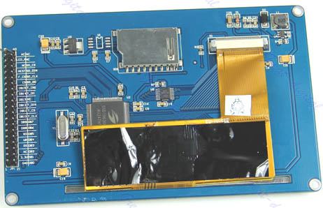
In addition to the SPI and I2C based controllers the PicoMite firmware supports LCD displays using the SSD1963 controller (as illustrated) and the ILI9341 controller.
These use a parallel interface, are available in sizes from 2.8" to 9" and have better specifications than the smaller displays. All these displays have an SD Card socket which is fully supported by MMBasic. On eBay you can find suitable displays by searching for the controller’s name (eg SSD1963).
Because they use a parallel interface data can be transferred much faster than an SPI interface resulting in a very quick screen update.
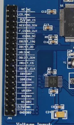
The characteristics of these displays are:
- A 2.8, 3.2, 4.3, 5, 7, 8 or 9 inch display
- Resolution of 320 x 240, 480 x 272 pixels (4.3" version) or 800 x 480 pixels (5”, 7", 8" or 9" versions).
- An SSD1963 display controller or ILI9341 display controller with a parallel interface (8080 format)
- A touch controller (SPI interface).
- A full sized SD Card socket.
There are a number of different designs using the SSD1963 controller but fortunately most suppliers have standardised on a single connector as illustrated on the right.
It is strongly recommended that any display purchased has a matching connector
– this provides some confidence that the manufacturer has followed the standard
that the PicoMite firmware is designed to use.
Connecting an 8-bit parallel LCD Panel
The controller uses a parallel interface while the touch controller and SD Card use an SPI interface. The touch and SD Card features are optional but if they are used they will use the second SPI port (SPI2).
The following table lists the connections required between the display board and the Raspberry Pi Pico to support the 8-bit parallel interface and the LCD display. The touch controller and SD Card interfaces are listed below.
| 8-bit parallel Display | Description | Raspberry Pi Pico |
|---|---|---|
| DB0 | Parallel Data Bus bit 0 | Pin 1/GP0 |
| DB1 | Parallel Data Bus bit 1 | Pin 2/GP1 |
| DB2 | Parallel Data Bus bit 2 | Pin 4/GP2 |
| DB3 | Parallel Data Bus bit 3 | Pin 5/GP3 |
| DB4 | Parallel Data Bus bit 4 | Pin 6/GP4 |
| DB5 | Parallel Data Bus bit 5 | Pin 7/GP5 |
| DB6 | Parallel Data Bus bit 6 | Pin 9/GP6 |
| DB7 | Parallel Data Bus bit 7 | Pin 10/GP7 |
| CS | Chip Select (active low) | Ground (ie, always selected) |
| WR | Write (active low) | Pin 19/GP14* |
| RD | Read (active low) | Pin 20/GP15* |
| DC | Command/Data | Pin 17/GP13* |
| RESET | Reset the SSD1963 | Pin 21/GP16* |
| LED_A | Backlight control for an unmodified display panel | Configurable see OPTION LCDPANEL |
| 5V | 5V power for the backlight on some displays (most displays use the 3.3V supply for this) | |
| 3.3V | Power supply. | |
| GND | Ground |
* Pins DC, WR, RD, RESET can be allocated to other pins as a block of 4 using the optional parameter DCpin
The following table lists the connections required to support the touch controller interface: 8-bit parallel
| Display | Raspberry Pi Pico | Description |
|---|---|---|
| T_CS | Touch Chip Select | Recommended Pin 24/GP18 |
| T_IRQ | Touch Interrupt | Recommended Pin 25/GP19 |
| T_DIN | Touch Data In (MOSI) | Recommended Pin 15/GP11 |
| T_CLK | Touch SPI Clock | Recommended Pin 14/GP10 |
| T_DO | Touch Data Out (MISO) | Recommended Pin 16/GP12 |
The following table lists the connections required to support the SD Card connector:
| 8-bit parallel Display | Description | Raspberry Pi Pico |
|---|---|---|
| SD_CS | SD Card Chip Select | Recommended Pin 29/GP22 |
| SD_DIN | SD Card Data In (MOSI) | Recommended Pin 15/GP11 |
| SD_CLK | SD Card SPI Clock | Recommended Pin 14/GP10 |
| SD_DO | SD Card Data Out (MISO) | Recommended Pin 16/GP12 |
Where a connection is listed as "Recommended" this is only a suggestion and other pins can be used depending on the hardware configuration. Regardless, the specific pin should be specified in the appropriate OPTION command (see below).
Generally 7 inch and larger displays have a separate pin on the connector (marked 5V) for powering the backlight from a 5V supply. If this pin is not provided the backlight power will be drawn from the 3.3V pin. Note that the power drawn by the backlight can be considerable. For example, a 7 inch display will typically draw 330 mA from the 5V pin.
If the Pico’s 3,3V output is used for powering a panel plus its backlight, it may easily require more current than the Pico can supply. Symptoms of a marginal supply could include TOUCH calibration failures or SD access failures. In this case an external 3.3V supply should be used.
The current drawn by the backlight can also cause a voltage drop on the LCD display panel’s ground pin which can in turn shift the logic levels as seen by the display controller resulting in corrupted colours or text. An easy way of diagnosing this effect is to reduce the CPU speed to (say) 48MHz. If this fixes the problem it is a strong indication that this is the cause. Soldering power and ground wires direct to the LCD display panel’s PCB is one workaround.
Care must be taken with display panels that share the SPI port between a number of devices (SD Card, touch, etc).
In this case all the Chip Select signals must configured in MMBasic or disabled by a permanent connection to 3.3V. If this is not done the pin will float causing the wrong controller to respond to commands on the SPI bus.
In the PicoMite firmware either SPI channel can used to communicate with the touch controller and the SD Card interface as defined by the OPTION SYSTEM SPI setting. If this is set, that SPI channel will be unavailable to BASIC programs (which can use the other SPI channel).
Configuring an 8-bit parallel LCD Panel
To use the display MMBasic must be configured using the OPTION LCDPANEL command which is normally entered at the command prompt. Every time the PicoMite firmware is restarted MMBasic will automatically initialise the display.
The syntax is:
OPTION LCDPANEL controller, orientation [,backlightpin] [,DCpin] [,NORESET] [DB0pin]
Where 'controller' can be either:
- SSD1963_4 : For a 4.3 inch display
- SSD1963_5 : For a 5 inch display
- SSD1963_5A : For an alternative version of the 5 inch display if SSD1963_5 does not work
- SSD1963_7 for a 7 inch display
- SSD1963_7A for an alternative version of the 7 inch display if SSD1963_7 does not work.
- SSD1963_8 for 8 inch or 9 inch displays.
- ILI9341_8 for a 2.8” or 3.2” display
orientation can be LANDSCAPE, PORTRAIT, RLANDSCAPE or RPORTRAIT. These can be abbreviated to
L, P, RL or RP. The R prefix indicates the reverse or "upside down" orientation.
DCpin is optional and is the Data/Command pin (previously called the RS pin). If this parameter is omitted the pin assignment will be as above in the table. If it is specified then DC, WR, RD and RESET pins will be assigned sequentially from DC pin.
The optional NORESET parameter can be used to save a pin. In this case the reset pin should be tied high. The optional DB0pin is only applicable to the RP2350B and can be used to specify the start pin for the 8 or 16 consecutive data pins used by the display.
This command only needs to be run once. From then on MMBasic will automatically initialise the display on
startup or reset. In some circumstances it may be necessary to interrupt power to the LCD panel while the
PicoMite firmware is running (eg, to save battery power) and in that case the GUI RESET LCDPANEL
command can be used to reinitialise the display.
If the LCD panel is no longer required the command OPTION LCDPANEL DISABLE can be used which will
return the I/O pins for general use.
To verify the configuration you can use the command OPTION LIST to list all options that have been set
including the configuration of the LCD panel.
To test the display you can enter the command GUI TEST LCDPANEL. You should see an animated display of colour circles being rapidly drawn on top of each other. Press the space bar on the console’s keyboard to stop the test.
8 and 9 inch Displays
The controller configuration SSD1963_8 has only been tested with the 8 and 9 inch displays made by EastRising (available at http://www.buydisplay.com). These must be purchased as a TFT LCD panel with 8080 interface, 800x480 pixel LCD, SSD1963 display controller and XPT2046 touch controller.
Note that the EastRising panels use a non-standard interface connector pin-out so you will need to refer to their data sheets when connecting these to the Raspberry Pi Pico. A suitable adapter to convert to the standard 40-pin connection can be purchased from: https://www.rictech.nz/micromite-products
16-bit Parallel LCD Panels
SSD1963 panels can also be enabled for 16-bit parallel operation. In this case, by default, pins GP0-GP15 are used for the data connections and, by default, pins GP16 to GP19 are used for the control signals DC, WR, RD and RESET.
For systems using the RP2350B only the data pins used can be selected by using the optional DB0pin parameter in the configuration command. To enable 16-bit operation append “_16” to the controller. Eg, SD1963_4_16.
The firmware also supports ILI9341, ILI9486, NT35510 and OTM8009A panels in 16-bit mode using the controller types ILI9341_16, ILI9486_16, and IPS_4_16 (supports both NT35510 and OTM8009A).
Valid 16-bit 'controllers' can be:
SSD1963_4_16For a 4.3 inch displaySSD1963_5_16For a 5 inch displaySSD1963_5A_16For an alternative version of the 5 inch display ifSSD1963_5does not workSSD1963_5ER_16For the 5 inch EastRising panelSSD1963_7_16For a 7 inch displaySSD1963_7A_16For an alternative version of the 7 inch display ifSSD1963_7does not work.SSD1963_7ER_16For the 7 inch EastRising panelSSD1963_8_16For 8 inch or 9 inch displays.ILI9341_16For a 2.8” or 3.2” displayILI9486_16Also supports NXP R61529IPS_4_16
Backlight Control
For the ILI9163, ILI9341, ST7735, ST7735S, SSD1331, ST7789, ILI9481, ILI9488, ILI9488W, ST7789_135, ILI9341_8 and ST7789_320 displays an optional parameter , backlight can be added to the end of the configuration parameters which specifies a pin to use to control the brightness of the backlight (LED_A). This will setup a PWM output on that pin with a frequency of 50KHz and an initial duty cycle of 99%.
You can then use the BACKLIGHT command to change the brightness between 0 and 100%. The PWM channel
is blocked for normal PWM use and must not conflict with the PWM channel that may be set up for audio.
For example:
OPTION LCDPANEL ILI9341, OR, DC, RESET, CS, GP11
The backlight can then be set to 40% with this command:
BACKLIGHT 40
Most SSD1963 based LCD panels have three pairs of solder pads on the PCB which are grouped under the heading "Backlight Control" as illustrated on the right.
Normally the pair marked "LED-A" are shorted together with a zero ohm resistor and this allows control of the backlight's brightness with a PWM (pulse width modulated) signal on the LED-A pin of the display panel's main connector.
However, it is better to use the SSD1963 controller to generate this signal as it frees up one I/O pin and allows finer control.
To use the SSD1963 control, the zero ohm resistor should be removed from the pair marked "LED-A" and used to short the nearby pair of solder pads marked "1963-PWM". The brightness can then be set using the
BACKLIGHT command via the SSD1963 controller (this is automatic, nothing needs to be configured).
Touch Support
Many LCD panels are supplied with a resistive touch sensitive panel and associated controller chip. MMBasic fully supports this interface and this allows many of the physical knobs and switches used in a project to be implemented as on-screen controls activated by touch.
In all cases the LCD display panel itself should be configured and tested first, then the touch feature can be configured. The touch controller uses the SPI protocol for communications and for LCD panels using the SPI protocol this has normally been previously done using the OPTION SYSTEM SPI command.
For display panels using I2C or a parallel interface the OPTION SYSTEM SPI command must be separately
used to define the system SPI bus for use by the touch controller. This command was discussed near the start of this chapter and defined in detail in the Options chapter of this manual.
For example, using the recommended pins for an 8-bit parallel display (described above) you would use:
OPTION SYSTEM SPI GP10, GP11, GP12
To use the touch facility MMBasic must be told that the touch controller is available on the system SPI bus by using the OPTION TOUCH command. This tells MMBasic what pins are used for the Chip Select and Interrupt signals.
As an example, for a typical ILI9341 display, this sets Chip Select to the GP12 pin and Interrupt to GP11:
OPTION TOUCH GP12, GP11
This must be entered at the command prompt and will cause the firmware to restart and disconnect the USB console interface, which will need to be reconnected.
When the PicoMite firmware is restarted MMBasic will automatically initialise the touch controller. To verify the configuration, you can use the command OPTION LIST to list all options that have been set including the configuration of the display panel and touch.
Care must be taken when the SPI port is shared between a number of devices (SD Card, touch, etc). In this case all the Chip Select signals must configured in MMBasic or alternatively disabled.
Calibrating the Touch Screen
Before the touch facility can be used it must be calibrated using the GUI CALIBRATE command.
This command will present a target in the top left corner of the screen (as illustrated). Using a pointy but blunt object (such as a toothpick) press exactly on the centre of the target and hold it down for at least a second.
MMBasic will record this location and then continue the calibration by sequentially displaying the target in the other three corners of the screen for touch and calibration. The calibration routine may warn that the calibration was not accurate. This is just a warning and you can still use the touch feature if you wish but it would be better to repeat the calibration using more care.
Following calibration you can test the touch facility using the GUI TEST TOUCH command. This command will blank the screen and wait for a touch. When the screen is touched a white dot will be placed on the display marking the position on the screen. If the calibration was carried out successfully the dot should be displayed exactly under the location of the stylus on the screen. To exit the test routine you can press the space bar on the console’s keyboard.
Touch Functions To detect if and where the screen is touched you can use the following functions in a BASIC program:
TOUCH(X)Returns the X coordinate of the currently touched location or -1 if the screen is not being touched.TOUCH(Y)Returns the Y coordinate of the currently touched location or -1 if the screen is not being touched.
Touch Interrupts
An interrupt can be set on the IRQ pin number that was specified when the touch facility was configured. To detect touch down the interrupt should be configured as INTL (i.e., high to low). The interrupt can be
cancelled with the command SETPIN pin, OFF.
The following program illustrates how the touch interrupt can be used. Whenever the screen is touched it will print on the console the coordinates of that touch. It assumes that the command OPTION TOUCH 7, 15 was used to initially configure the touch function:
SETPIN 15, INTL, MyInt  ' assumes that OPTION TOUCH 7, 15 was used
DO : LOOP

SUB MyInt               ' subroutine called on a touch interrupt
PRINT TOUCH(X) TOUCH(Y)
END SUB
LCD Display as the Console Output
A PS2 or USB keyboard can be used with an LCD display panel to create a fully self contained computer that will boot direct to the MMBasic prompt. This feature works particularly well with 5 and 7 inch LCD panels using the SSD1963 controller. These can display a lot of text and update rapidly resulting in a user experience that is comparable to a PicoMite based computer using VGA or HDMI video output.
The LCD must be first configured using OPTION LCDPANEL. Then, to enable the console output on the LCD panel, you should use the following command:
OPTION LCDPANEL CONSOLE [font [, fc [, bc [, blight]]] [,NOSCROLL]
font is the default font, fc is the default foreground colour, bc is the default background colour and blight is the default backlight brightness (2 to 100). These settings are saved in flash and are used to configure MMBasic at power up. They are all optional and default to font 2, white, black and 100%.
On displays where the framebuffer cannot be read, the firmware will automatically set the NOSCROLL option. When this is set and output reaches the bottom of the screen the screen is cleared and output continues again at the top. This also applies to the in-built editor. For SPI displays that can read the framebuffer (eg ILI9341) scrolling is very slow so the NOSCROLL parameter can be set to improve output and editing performance.
Note that this isn’t necessary if the display is used in portrait mode as H/W scrolling is then used.
Colour coding in the editor is also turned on by this command (see the chapter Full Screen Editor). To disable using the LCD panel as the console the command is OPTION LCDPANEL NOCONSOLE.
Example SPI LCD Panel Configuration
The following is a summary of how a typical LCD panel using an ILI9341 controller can be connected. This example supports the SD Card socket, the LCD display and the touch interface.
Typical panels can be found on ebay.com and similar sites by searching for the keyword “ILI9341”. Make sure that the connections on the rear of the panel resemble that shown below:
The panel should be connected to the Raspberry Pi Pico as illustrated:
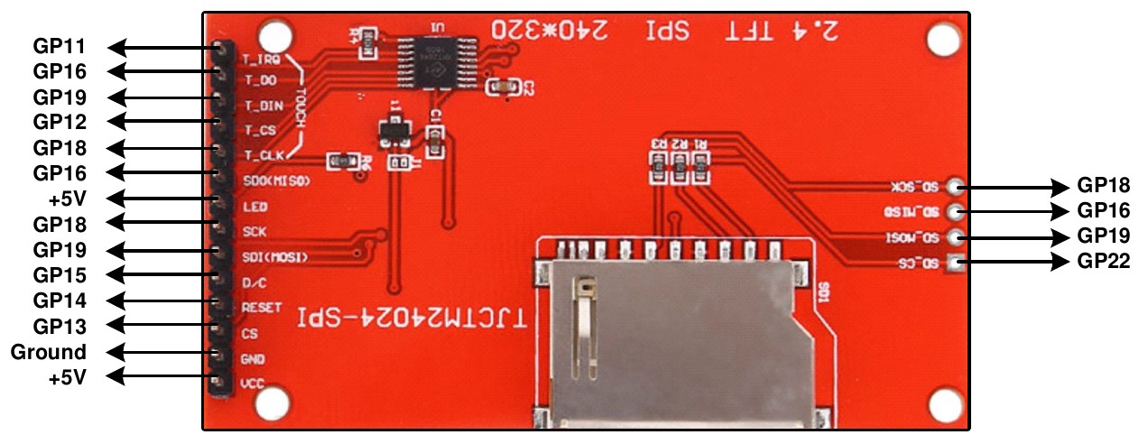
To match the above connections the following configuration commands should be entered, one by one at the command prompt:
OPTION SYSTEM SPI GP18, GP19, GP16
OPTION LCDPANEL ILI9341, L, GP15, GP14, GP13
OPTION TOUCH GP12, GP11
OPTION SDCARD GP22
These commands will be remembered and automatically applied on power up. Note that after each command is entered the firmware will restart, and the USB connection will be lost and must be reconnected.
Next the touch screen should be calibrated with:
GUI CALIBRATE
You can then test the various components.
The following will draw multiple colourful overlapping circles on the LCD screen which will confirm that the LCD is connected correctly:
GUI TEST LCDPANEL
The following will test the touch interface. When you touch the LCD screen a dot should appear on the screen at the exact point of the touch.
GUI TEST TOUCH
If this is not accurate you may have to run the GUI CALIBRATE command a second time taking greater care.
Finally, the following will list the files on the SD Card, if it executes without error you can be assured that the SD Card interface is good.
FILES
If you run into trouble getting the display to work it is worth disconnecting everything and clear the options with the command OPTION RESET so that you can start with a clean slate. Then reconnect it one stage at a time and configure and test each new stage as you progress. As you do this remember that any device connected to the SPI bus must be configured in MMBasic or its chip select line must be held logic high. This is because the voltage on an unconnected chip select line will float, possibly causing the wrong device to respond to signals intended for another device.
Also note that the ILI9341 controller is very sensitive to static discharge so, if the panel will not respond, it could easily be damaged and it would be worth testing with another panel.
Graphics Functions
These commands and functions operate on attached LCD panels and VGA/HDMI video outputs. A tutorial on using these facilities is included in the firmware distribution file.
See the file: Graphics in the PicoMite.pdf
Colours
Colour is specified as a true colour 24 bit number where the top eight bits represent the intensity of the red colour, the middle eight bits the green intensity and the bottom eight bits the blue. The easiest way to generate this number is with the RGB() function which has the form:
RGB(red, green, blue)
The RGB() function also supports a shortcut where you can specify common colours by naming them. For example, RGB(red) or RGB(cyan). The colours that can be named using the shortcut form are white, black, blue, green, cyan, red, magenta, yellow, brown, white, orange, pink, gold, salmon, beige, lightgrey and grey (or USA spelling gray/lightgray).
MMBasic will automatically translate all colours to the format required by the individual display controller.
For example, in the case of the ILI9341 LCD controller, is 64K colours in the 565 format.
The default for commands that require a colour parameter can be set with the COLOUR command (can also be spelt COLOR). This is handy if your program uses a consistent colour scheme, you can then set the defaults and use the short version of the drawing commands throughout your program.
The COLOUR command takes the format: COLOUR foreground-colour, background-colour
Fonts
also see the chapter on fonts for detailed depictions
Built-in Fonts
There are eight built in fonts. These are:
| Font Number | Size (width x height) | Character Set | Description |
|---|---|---|---|
| 1 | 8 x 12 | All 95 ASCII characters plus 7F to FF (hex) | Standard font (default on start-up). |
| 2 | 12 x 20 | All 95 ASCII characters | Medium sized font. |
| 3 | 16 x 16 (VGA) 16 x 24 (HDMI, LCD) | All 95 ASCII characters | A large font |
| 4 | 10x16 | All 95 ASCII characters plus 7F to FF (hex) | A font with extended graphic characters. Suitable for high resolution displays. |
| 5 | 24 x 32 | All 95 ASCII characters | Extra large font, very clear. |
| 6 | 32 x 50 | 0 to 9 + some symbols | Numbers plus decimal point, positive, negative, equals, degree and colon symbols. Very clear. |
| 7 | 6x8 | All 95 ASCII characters | A small font useful when low resolutions are used. |
| 8 | 4x6 | All 95 ASCII characters | An even smaller font. |

Note that font 3 has a 16 x 16 pixel size when used with VGA video output but a 16 x 24 size for HDMI and LCD panels.
In all fonts (including font #6) the back quote character ` (60 hex or 96 decimal) has been replaced with the degree symbol º.
Font #1 (the default font) and font #4 have an extended character set covering all characters from CHR$(32) to CHR$(255) or 20 to FF (hex) as illustrated on the right.
Embedded Fonts
If required, additional fonts can be embedded in a BASIC program. These fonts work exactly same as the built in font (i.e. selected using the FONT command or specified in the TEXT command).
The format of an embedded font is:
DefineFont #Nbr
  hex [[ hex[…]
  hex [[ hex[…]
END DefineFont
It must start with the keyword "DefineFont" followed by the font number (which may be preceded by an optional # character). Any font number in the range of 2 to 5 and 8 to 16 can be specified and if it is the same as a built in font it will replace that font.
The body of the font is a sequence of 8-digit hex words with each word separated by one or more spaces or a new line. The font definition is terminated by an End DefineFont keyword. These can be placed anywhere in a program and MMBasic will skip over it. This format is the same as that used by the Micromite.
Additional fonts and information can be found in the Embedded Fonts folder in the PicoMite firmware download. These fonts cover a wide range of character sets including a symbol font (Dingbats) which is handy for creating on screen icons, etc.
Screen Coordinates
All coordinates and measurements on the screen are done in terms of pixels with the X coordinate being the horizontal position and Y the vertical position. The top left corner of the screen has the coordinates X = 0 and Y = 0 and the values increase as you move down and to the right of the screen.
There are four read only variables which provide useful information about the display currently connected:
MM.HRES: Returns the width of the display (the X axis) in pixels.MM.VRES: Returns the height of the display (the Y axis) in pixels.MM.INFO(FONTHEIGHT): Returns the height of the current default font (in pixels). All characters in a font have the same height.MM.INFO(FONTWIDTH): Returns the width of a character in the current font (in pixels). All characters have the same width.
Drawing Commands
There are ten basic drawing commands that you can use within MMBasic programs to draw graphics. Most of these have optional parameters. You can completely leave these off the end of a command or you can use two commas in sequence to indicate a missing parameter. For example, the fifth parameter of the LINE command is optional so you can use this format:
LINE 0, 0, 100, 100, , rgb(red)
Optional parameters are indicated below by italics, for example: font
In the following commands C is the drawing colour and defaults to the current foreground colour. FILL is the fill colour which defaults to -1 which indicates that no fill is to be used.
The basic drawing commands are:
-
CLS CClears the screen to the colour C.
If C is not specified the current default background colour will be used.
-
PIXEL X, Y, CIlluminates a pixel.If C is not specified the current default foreground colour will be used.
-
LINE X1, Y1, X2, Y2, LW, CDraws a line starting at X1 and Y1 and ending at X2 and Y2.
LW is the line’s width and is only valid for horizontal or vertical lines. It defaults to 1 if not specified or if the line is a diagonal.
There is an extended version for diagonal lines (see LINE AAA).
-
BOX X, Y, W, H, LW, C, FILLDraws a box starting at X and Y which is W pixels wide and H pixels high.
LW is the width of the sides of the box and can be zero. It defaults to 1.
-
RBOX X, Y, W, H, R, C, FILLDraws a box with rounded corners starting at X and Y which is W pixels wide and H pixels high.
R is the radius of the corners of the box. It defaults to 10.
-
CIRCLE X, Y, R, LW, A, C, FILLDraws a circle with X and Y as the centre and a radius R.
LWis the width of the line used for the circumference and can be zero (defaults to 1).A is the aspect ratio which is a floating point number and defaults to 1.
For example, an aspect of 0.5 will draw an oval where the width is half the height.
-
TEXT X, Y, STRING, ALIGNMENT, FONT, SCALE, C, BCDisplays a string starting at X and Y.
ALIGNMENTis 0, 1 or 2 characters (a string expression or variable is also allowed) where the first letter is the horizontal alignment around X and can be L, C or R forLEFT,CENTERorRIGHTaligned text and the second letter is the vertical alignment around Y and can be T, M or B forTOP,MIDDLEorBOTTOMaligned text. The default alignment is left/top.An additional code letter can be used to rotate the text (see below for the details).
FONTandSCALEare optional and default to that set by theFONTcommand.C is the drawing colour and
BCis the background colour. They are optional and default to that set by theCOLOURcommand. -
GUI BITMAP X, Y, BITS, WIDTH, HEIGHT, SCALE, C, BCDisplays the bits in a bitmap starting at X and Y.
HEIGHTandWIDTHare the dimensions of the bitmap as displayed on the LCD panel and default to 8x8.SCALE, C andBCare the same as for theTEXTcommand.The bitmap can be an integer or a string variable or constant and is drawn using the first byte as the first bits of the top line (bit 7 first, then bit 6, etc) followed by the next byte, etc.
When the top line has been filled the next line of the displayed bitmap will start with the next bit in the integer or string.
-
POLYGON n, xarray%(), yarray%() [, bordercolour] [, fillcolour]Draws a filled or outline polygon with n xy-coordinate pairs in
xarray%()andyarray%().If
fillcolouris omitted then just the polygon outline is drawn.If
bordercolouris omitted then it will default to the current default foreground colour. -
ARC x, y, r1, [r2], a1, a2 [, c]Draws an arc of a circle with a given colour and width between two radials (defined in degrees).
Parameters for the
ARCcommand are the x and y coordinates of the centre of the arc, the inner and outer radii, the start and end angles of the arc and the colour of the arc. The zero degrees reference is at the 12 o’clock position
Rotated Text
As described above the alignment of the text in the TEXT command can be specified by using one or two characters in a string expression for the third parameter of the command. In this string you can also specify a 3ʳᵈ character to indicate the rotation of the text.
| 3ʳᵈ char | Meaning | Description |
|---|---|---|
N | normal | normal orientation (default) |
V | vertical | for vertical text with each character under the previous running from top to bottom. |
I | inverted | the text will be inverted (i.e. upside down) |
U | up | the text will be rotated counter clockwise by 90º |
D | down | the text will be rotated clockwise by 90º |
As an example, the following will display the text "LCD Display" vertically down the left hand margin of the display panel and centred vertically:
TEXT 0, 250, "LCD Display", "LMV", 5
Positioning is relative to the top left corner of the character when viewed normally so inverted 100,100 will have the top left pixel of the first character at 100,100 and the text will then be above y=101 and to the left of x=101. Similarly, R in the alignment string is viewed from the perspective of the character in whatever orientation it is in (not the screen).
Transparent Text
The VGA or HDMI video output or LCD displays using the SSD1963, ST7796S, ILI9341, ST7789_320, or ILI9488 with MISO connected are capable of transparent text.
In this case the TEXT command will allow the use of -1 for the background colour. This means that the text is drawn over the background with the background image showing through the gaps in the letters.
Framebuffers and Layers
All variants of the firmware can create one or two in memory framebuffers and one or two layer buffers (this is memory dependent). These are areas of memory with the same width and height as the main display. In the case of HDMI and VGA displays they will have the same colour depth as the current mode. In the case of LCD displays, they will have 4-bits per pixel (16 colours).
Depending on the version of the firmware and current display mode, creation of framebuffers or layer buffers will either use pre-allocated memory or allocate memory from user memory.
Framebuffers can be used to construct image data that can be copied to the physical display. Layer buffers are typically used to create partial images that can sit on top of a background display image and provide an efficient method of moving display elements over a static background.
All standard graphics drawing commands can be used on a framebuffer or layer buffer in the same way as if
writing to the physical display. The FRAMEBUFFER WRITE command is used to direct the destination of the
graphic output using a code.
The code is a single character which can be:
NThe physical output device.FThe framebuffer.2A second framebuffer (RP2350 only)LThe layerbufferTA second layerbuffer (RP2350 only)
The basic framebuffer commands are:
FRAMEBUFFER CREATE  ‘ code F
FRAMEBUFFER LAYER   ‘ code L
FRAMEBUFFER CLOSE
FRAMEBUFFER WRITE code
FRAMEBUFFER COPY code1, code2 [,B]
See the detail command descriptions for addition framebuffer commands.
In the case of VGA and HDMI versions of the firmware, depending on the display mode and CPU speed (>=252MHz), layers are automatically applied on top of the main display image as it is output to the screen. In the case of LCD displays the FRAMEBUFFER MERGE command is used to create the final image from a framebuffer and a layer buffer. The game PETSCII robots shows how this technique can be used to great effect.
The automatic application of a layer buffer is implemented in VGA versions mode 2 and mode 3 (RP2350 only) as well as HDMI modes 2, 3, 4, and 5. Two layers buffers are only available on the RP2350 and in the following modes: VGA mode 2, HDMI modes 2 and 5.
BLIT and Sprite Commands
In previous versions of the firmware the blit and sprite commands were synonyms for the same functionality. In release 6.00.00 onwards they are separate commands. The distinction is that BLIT is a simple memory operation copying to and from a display or memory to a display or memory. Sprites are more complex and allow the programmer to display elements over a background and then move them over the background without corrupting the background image. In addition, the programmer can use the sprite functionality to detect collisions between sprites and between a sprite and the edges of the display.
Sprites cannot be used unless the display supports reading from its framebuffer and blit functionality is also limited unless this is the case. Sprites are enabled for all versions of the firmware when used on a an in-memory framebuffer and VGA and HDMI versions of the firmware directly with the screen.
Sprites are always stored as RGB121 nibbles with 2 pixels to a byte. In contrast BLIT buffers are stored as RGB888 values and so can be used with full colour LCD displays. Of course this comes at the expense of significantly greater memory usage.
See the SPRITE command and function together with Appendix G for more information on using sprites.
If the display is capable of transparent text the BLIT command allows a portion of the image currently showing on the display to be copied to a memory buffer and later copied back to the display. This is useful when something needs to be drawn over the background and later removed without damaging the image in the background. Examples include a game where a character is moving about in front of a landscape or the moving needle of a photorealistic gauge.
The available standard blit commands are:
BLIT READ #b, x, y, w, h
BLIT WRITE #b, x, y [,mode]
BLIT LOAD #b, f$, x, y, w, h
BLIT CLOSE #b
#b is the buffer number in the range of 1 to 64.
x and y are the coordinates of the top left corner and w and h are the width and height of the image.
READ will copy the display image to the buffer,
WRITE will copy the buffer to the display and CLOSE will free up the buffer and reclaim the memory used. LOAD will load an image file into the buffer.
BLIT LOAD and BLIT WRITE will work on any display while BLIT and BLIT READ will only work on displays capable of transparent text (i.e. using the SSD1963, ILI9341, ST7789_320, or ILI9488 with MISO connected) as well as VGA and HDMI displays and any in-memory framebuffers
These commands can be used to copy a portion of the display to another location (by copying to a buffer then writing somewhere else) but a simpler method is to use an alternative version of the BLIT command as follows:
BLIT x1, y1, x2, y2, w, h
This will copy a portion of the image at x1/y1 to the location x2/y2. w and h specify the width and height of the image to be copied. The source and destination areas can overlap and the BLIT command will perform the copy correctly.
This form of the BLIT command is particularly useful for creating graphs that can scroll horizontally or vertically as new data is added.
In addition, the firmware provides BLIT MEMORY, BLIT COMPRESSED, BLIT FRAMEBUFFER, and BLIT MERGE commands.
These advanced commands can be used to help code games with hundreds of display elements such as the port to MMBasic of PETSCII robots.
Load Image
The LOAD IMAGE and LOAD JPG commands can be used to load an image from the Flash Filesystem or SD
Card and display it on the LCD display. This can be used to draw a logo or add an ornate background to the
graphics drawn on the display.
Advanced Graphics
NOT AVAILABLE IN VGA/HDMI AND WEBMITE RP2040 VERSIONS
The PicoMite firmware includes a suite of advanced graphics functions to make it easy for a programmer to create touch sensitive control elements on an LCD panel as illustrated. These include on screen switches, buttons, indicator lights, keyboard, etc.
MMBasic will draw the control and animate it (ie, a switch will appear to depress when touched). All that the BASIC programmer needs to do is invoke a single command to specify the basic details of the control.
These functions make it easy to create a control panel to manage any control functions like a lathe, motor controller, heating system, small industrial process and so on.
The Advanced Graphics functions are described in detail in the document Advanced Graphics Functions.pdf which is included in the firmware download file.
3D Engine
NOT AVAILABLE IN WEBMITE VERSIONS
The 3D Engine includes ten commands for manipulating 3D images including setting the camera, creating, hiding, rotating, etc. See the document Appendix J - The CMM2 3D engine for a full description of these commands and how to use them.
LCD Graphics Example
As an example of using the simple graphics commands the following program will draw a simple digital clock on an ILI9341 based LCD display. The program will terminate and return to the command prompt if the display screen is touched.
First the display and touch options must be configured by entering the commands listed at the beginning of this chapter. The exact format of these will depend on how you have connected the display panel.
Then enter and run the program:
CONST DBlue = RGB(0, 0, 128)         ' A dark blue colour
COLOUR RGB(GREEN), RGB(BLACK)        ' Set the default colours
FONT 1, 3                            ' Set the default font
BOX 0, 0, MM.HRes-1, MM.VRes/2, 3, RGB(RED), DBlue
DO
TEXT MM.HRes/2, MM.VRes/4, TIME$, "CM", 1, 4, RGB(CYAN), DBlue
TEXT MM.HRes/2, MM.VRes*3/4, DATE$, "CM"
IF TOUCH(X) <> -1 THEN END
LOOP
This program starts by defining a constant with a value corresponding to a dark blue colour and then sets the defaults for the colours and the font. It then draws a box with red walls and a dark blue interior.
Following this the program enters a continuous loop where it performs three functions:
- Displays the current time inside the previously drawn box. The string is drawn centred both horizontally and vertically in the middle of the box. Note that the
TEXTcommand overrides both the default font and colours to set its own parameters. - Draws the date centred in the lower half of the screen. In this case the
TEXTcommand uses the default font and colours previously set. - Checks for a touch on the screen. This is indicated when the
TOUCH(X)function returns something other than-1. In that case the program will terminate.
The screen display should look like this (the font used in this illustration is different):
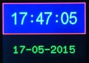
Supported Hardware
LCD Panels
The resolution and number of colours supported by an LCD panel is determined by the panel itself and the driver – see the chapter Display Panels for the details.
VGA Video
There are a number of modes which can be selected using the MODE command:
OPTION RESOLUTION 640x480
| MODE | RESOLUTION | COLOUR | BUFFER |
|---|---|---|---|
| MODE 1 | 640x480 | monochrome with RGB121 tiles | optional layer buffer |
| MODE 2 | 320x240 | 4-bit colour | optional layer buffer (RP2350 only) 2nd optional layer buffer |
| MODE 3 | 640x480 | 4-bit colour | optional layer buffer (RP2350 only) |
OPTION RESOLUTION 720x400
| MODE | RESOLUTION | COLOUR | BUFFER |
|---|---|---|---|
| MODE 1 | 720x400 | monochrome with RGB121 tiles | optional layer buffer |
| MODE 2 | 360x200 | 4-bit colour | |
| MODE 3 | 720x400 | 4-bit colour |
OPTION RESOLUTION 800x600 (RP2350 only)
| MODE | RESOLUTION | COLOUR | BUFFER |
|---|---|---|---|
| MODE 1 | 800x600 | monochrome with RGB121 tiles | optional layer buffer |
| MODE 2 | 400x300 | 4-bit colour | two optional layers |
| MODE 3 | 800x600 | 4-bit colour | optional layer buffer |
OPTION RESOLUTION 848x480 (RP2350 only)
| MODE | RESOLUTION | COLOUR | BUFFER |
|---|---|---|---|
| MODE 1 | 848x480 | monochrome with RGB121 tiles | optional layer buffer |
| MODE 2 | 424x240 | 4-bit colour | two optional layers |
| MODE 3 | 848x480 | 4-bit colour | optional layer buffer |
HDMI Video (RP2350 only)
Each HDMI resolution can operate in a number of modes which are set using the MODE command:
OPTION RESOLUTION 640x480
| MODE | RESOLUTION-COLOUR | BUFFER |
|---|---|---|
| MODE 1 | 640x480x2-colours with RGB555 | optional layer buffer |
| MODE 2 | 320x240x16colours and colour mapping to RGB555 palette | two optional layers |
| MODE 3 | 640x480x16 colours and colour mapping to RGB555 palette | optional layer buffer |
| MODE 4 | 320x240x32768 colours | optional layer buffer |
| MODE 5 | 320x240x256 colours and colour mapping to RGB555 palette | optional layer buffer |
OPTION RESOLUTION 720x400
| MODE | RESOLUTION-COLOUR | BUFFER |
|---|---|---|
| MODE 1 | 720x400 monochrome with RGB555 tiles | optional layer buffer |
| MODE 2 | 360x200 4-bit colour and colour mapping to RGB555 palette | two optional layers |
| MODE 3 | 720x400 4-bit colour and colour mapping to RGB555 palette | optional layer buffer |
| MODE 4 | 360x200x32768 colours | optional layer buffer |
| MODE 5 | 360x200x256 colours and colour mapping to RGB555 palette | optional layer buffer |
OPTION RESOLUTION 800x600 (RP2350 only)
MODE 1 | 800x600 monochrome with RGB332 tiles| optional layer buffer MODE 2 | 400x300 4-bit colour and colour mapping to RGB332 palette| optional layer buffer MODE 3 | 800x600 4-bit colour and colour mapping to RGB332 palette| optional layer buffer MODE 5 | 400x300x256 colours| optional layer buffer
OPTION RESOLUTION 848x480 (RP2350 only)
MODE 1 | 848x480 monochrome with RGB332 tiles| optional layer buffer MODE 2 | 424x240 4-bit colour and colour mapping to RGB332 palette| optional layer buffer MODE 3 | 848x480 4-bit colour and colour mapping to RGB332 palette| optional layer buffer MODE 5 | 424x240x256 colours| optional layer buffer
OPTION RESOLUTION 1280x720
MODE 1 | 1280x720x2-colours with RGB332| optional layer buffer MODE 2 | 320x180x16colours and colour mapping to RGB332 palette| optional layer buffer MODE 3 | 640x360x16 colours and colour mapping to RGB332 palette| optional layer buffer MODE 5 | 320x180x256 colours| optional layer buffer
OPTION RESOLUTION 1024x768
MODE 1 | 1024x768x2-colours with RGB332tiles| optional layer buffer MODE 2 | 256x192x16colours and colour mapping to RGB332 palette| optional layer buffer MODE 3 | 512x384x16 colours and colour mapping to RGB332 palette| optional layer buffer MODE 5 | 256x192x256 colours| optional layer buffer
Fonts
There are 8 built-in fonts available on Picomite.
In all fonts (including font #6) the back quote character ` (60 hex or 96 decimal) has been replaced with the degree symbol º.
Font 1
default on startup
Dimensions: 8 x 12 pixels
All 95 ASCII characters plus 7F to FF (hex)
Font 2
Medium sized font
Dimensions: 12 x 20 pixels
All 95 ASCII characters
Font 3
A large font
This font has a height of 16 pixels size when used with VGA video output but a height of 24 pixels for HDMI and LCD panels.
Dimensions: 16 x 16 pixels (VGA), 16 x 24 pixels (HDMI, LCD)
All 95 ASCII characters
Font 4
A font with extended graphic characters. Default on HiRes displays
Suitable for high resolution displays.
Dimensions: 10 x 16 pixels (VGA), 16 x 24 pixels (HDMI, LCD)
All 95 ASCII characters plus 7F to FF (hex)
Font 5
Extra large font, very clear.
Dimensions: 24 x 32 pixels
All 95 ASCII characters
Font 6
Extra large font, very clear.
Dimensions: 32 x 50 pixels
Numbers 0-9 plus decimal point ., positive +, negative -, equals =, degree ° and colon ,.
Font 7
A small font useful when low resolutions are used.
Dimensions: 6 x 8 pixels
All 95 ASCII characters
Font 8
A extra small font
Dimensions: 4 x 6 pixels
All 95 ASCII characters
Character Set
Picomite uses an ASCII compatible character encoding.
Non-Printable ASCII characters (character code 0-31)
The first 32 characters in the ASCII-table are unprintable control codes and are used to control peripherals such as printers.
| Int | HEX | Symbol | Unicode Codepoint | Description |
|---|---|---|---|---|
| 00 | 00 | ␀ | U+00000 | Null character |
| 01 | 01 | ␁ | U+00001 | Start of Heading |
| 02 | 02 | ␂ | U+00002 | Start of Text |
| 03 | 03 | ␃ | U+00003 | End of Text |
| 04 | 04 | ␄ | U+00004 | End of Transmission |
| 05 | 05 | ␅ | U+00005 | Enquiry |
| 06 | 06 | ␆ | U+00006 | Acknowledge |
| 07 | 07 | ␇ | U+00007 | Bell, Alert |
| 08 | 08 | ␈ | U+00008 | Backspace |
| 09 | 09 | ␉ | U+00009 | Horizontal Tab |
| 10 | 0A | ␊ | U+0000A | Line Feed |
| 11 | 0B | ␋ | U+0000B | Vertical Tabulation |
| 12 | 0C | ␌ | U+0000C | Form Feed |
| 13 | 0D | ␍ | U+0000D | Carriage Return |
| 14 | 0E | ␎ | U+0000E | Shift Out |
| 15 | 0F | ␏ | U+0000F | Shift In |
| 16 | 10 | ␐ | U+00010 | Data Link Escape |
| 17 | 11 | ␑ | U+00011 | Device Control One (XON) |
| 18 | 12 | ␒ | U+00012 | Device Control Two |
| 19 | 13 | ␓ | U+00013 | Device Control Three (XOFF) |
| 20 | 14 | ␔ | U+00014 | Device Control Four |
| 21 | 15 | ␕ | U+00015 | Negative Acknowledge |
| 22 | 16 | ␖ | U+00016 | Synchronous Idle |
| 23 | 17 | ␗ | U+00017 | End of Transmission Block |
| 24 | 18 | ␘ | U+00018 | Cancel |
| 25 | 19 | ␙ | U+00019 | End of medium |
| 26 | 1A | ␚ | U+0001A | Substitute |
| 27 | 1B | ␛ | U+0001B | Escape |
| 28 | 1C | ␜ | U+0001C | File Separator |
| 29 | 1D | ␝ | U+0001D | Group Separator |
| 30 | 1E | ␞ | U+0001E | Record Separator |
| 31 | 1F | ␟ | U+0001F | Unit Separator |
Printable ASCII characters
Codes 32-127 are common for all the different variations of the ASCII table, they are called printable characters, represent letters, digits, punctuation marks, and a few miscellaneous symbols. You will find almost every character on your keyboard.
| Int | HEX | Symbol | Unicode Codepoint | Description | Font1 |
|---|---|---|---|---|---|
| 32 | 20 | SP | U+00020 | Space |  |
| 33 | 21 | ! | U+00021 | Exclamation mark |  |
| 34 | 22 | " | U+00022 | Double quotes (or speech marks) |  |
| 35 | 23 | # | U+00023 | Number sign |  |
| 36 | 24 | $ | U+00024 | Dollar |  |
| 37 | 25 | % | U+00025 | Per cent sign |  |
| 38 | 26 | & | U+00026 | Ampersand |  |
| 39 | 27 | ' | U+00027 | Single quote |  |
| 40 | 28 | ( | U+00028 | Open parenthesis (or open bracket) |  |
| 41 | 29 | ) | U+00029 | Close parenthesis (or close bracket) |  |
| 42 | 2A | * | U+0002A | Asterisk |  |
| 43 | 2B | + | U+0002B | Plus |  |
| 44 | 2C | , | U+0002C | Comma |  |
| 45 | 2D | - | U+0002D | Hyphen-minus |  |
| 46 | 2E | . | U+0002E | Period, dot or full stop |  |
| 47 | 2F | / | U+0002F | Slash or divide |  |
| 48 | 30 | 0 | U+00030 | Zero |  |
| 49 | 31 | 1 | U+00031 | One |  |
| 50 | 32 | 2 | U+00032 | Two |  |
| 51 | 33 | 3 | U+00033 | Three |  |
| 52 | 34 | 4 | U+00034 | Four |  |
| 53 | 35 | 5 | U+00035 | Five |  |
| 54 | 36 | 6 | U+00036 | Six |  |
| 55 | 37 | 7 | U+00037 | Seven |  |
| 56 | 38 | 8 | U+00038 | Eight |  |
| 57 | 39 | 9 | U+00039 | Nine |  |
| 58 | 3A | : | U+0003A | Colon |  |
| 59 | 3B | ; | U+0003B | Semicolon |  |
| 60 | 3C | < | U+0003C | Less than (or open angled bracket) |  |
| 61 | 3D | = | U+0003D | Equals |  |
| 62 | 3E | > | U+0003E | Greater than (or close angled bracket) |  |
| 63 | 3F | ? | U+0003F | Question mark |  |
| 64 | 40 | @ | U+00040 | At sign |  |
| 65 | 41 | A | U+00041 | Uppercase A |  |
| 66 | 42 | B | U+00042 | Uppercase B |  |
| 67 | 43 | C | U+00043 | Uppercase C |  |
| 68 | 44 | D | U+00044 | Uppercase D |  |
| 69 | 45 | E | U+00045 | Uppercase E |  |
| 70 | 46 | F | U+00046 | Uppercase F |  |
| 71 | 47 | G | U+00047 | Uppercase G |  |
| 72 | 48 | H | U+00048 | Uppercase H |  |
| 73 | 49 | I | U+00049 | Uppercase I |  |
| 74 | 4A | J | U+0004A | Uppercase J |  |
| 75 | 4B | K | U+0004B | Uppercase K |  |
| 76 | 4C | L | U+0004C | Uppercase L |  |
| 77 | 4D | M | U+0004D | Uppercase M |  |
| 78 | 4E | N | U+0004E | Uppercase N |  |
| 79 | 4F | O | U+0004F | Uppercase O |  |
| 80 | 50 | P | U+00050 | Uppercase P |  |
| 81 | 51 | Q | U+00051 | Uppercase Q |  |
| 82 | 52 | R | U+00052 | Uppercase R |  |
| 83 | 53 | S | U+00053 | Uppercase S |  |
| 84 | 54 | T | U+00054 | Uppercase T |  |
| 85 | 55 | U | U+00055 | Uppercase U |  |
| 86 | 56 | V | U+00056 | Uppercase V |  |
| 87 | 57 | W | U+00057 | Uppercase W |  |
| 88 | 58 | X | U+00058 | Uppercase X |  |
| 89 | 59 | Y | U+00059 | Uppercase Y |  |
| 90 | 5A | Z | U+0005A | Uppercase Z |  |
| 91 | 5B | [ | U+0005B | Opening bracket |  |
| 92 | 5C | \ | U+0005C | Backslash |  |
| 93 | 5D | ] | U+0005D | Closing bracket | ![]](fonts/font1/5D.png) |
| 94 | 5E | ^ | U+0005E | Caret - circumflex |  |
| 95 | 5F | _ | U+0005F | Underscore |  |
| 96 | 60 | ` | U+00060 | Grave accent |  |
| 97 | 61 | a | U+00061 | Lowercase a |  |
| 98 | 62 | b | U+00062 | Lowercase b |  |
| 99 | 63 | c | U+00063 | Lowercase c |  |
| 100 | 64 | d | U+00064 | Lowercase d |  |
| 101 | 65 | e | U+00065 | Lowercase e |  |
| 102 | 66 | f | U+00066 | Lowercase f |  |
| 103 | 67 | g | U+00067 | Lowercase g |  |
| 104 | 68 | h | U+00068 | Lowercase h |  |
| 105 | 69 | i | U+00069 | Lowercase i |  |
| 106 | 6A | j | U+0006A | Lowercase j |  |
| 107 | 6B | k | U+0006B | Lowercase k |  |
| 108 | 6C | l | U+0006C | Lowercase l |  |
| 109 | 6D | m | U+0006D | Lowercase m |  |
| 110 | 6E | n | U+0006E | Lowercase n |  |
| 111 | 6F | o | U+0006F | Lowercase o |  |
| 112 | 70 | p | U+00070 | Lowercase p |  |
| 113 | 71 | q | U+00071 | Lowercase q |  |
| 114 | 72 | r | U+00072 | Lowercase r |  |
| 115 | 73 | s | U+00073 | Lowercase s |  |
| 116 | 74 | t | U+00074 | Lowercase t |  |
| 117 | 75 | u | U+00075 | Lowercase u |  |
| 118 | 76 | v | U+00076 | Lowercase v |  |
| 119 | 77 | w | U+00077 | Lowercase w |  |
| 120 | 78 | x | U+00078 | Lowercase x |  |
| 121 | 79 | y | U+00079 | Lowercase y |  |
| 122 | 7A | z | U+0007A | Lowercase z |  |
| 123 | 7B | { | U+0007B | Opening brace |  |
| 124 | 7C | | | U+0007C | Vertical bar |  |
| 125 | 7D | } | U+0007D | Closing brace |  |
| 126 | 7E | ~ | U+0007E | Equivalency sign - tilde |  |
| 127 | 7F | ⌂ | U+2302 | HOUSE 1 2 |  |
Character 127 should represent the command DEL, but is replaced for all fonts on PicoMite.
Symbols
Fonts 1 and 4 have an extended character set. The symbols are not from the ASCII standard, some are not even in Unicode (as of 2025)
| Int | Char | Font 1 | Unicode Codepoint | Description |
|---|---|---|---|---|
| 128 | ☐ |  | U+2610 | BALLOT BOX |
| 129 | ☑ |  | U+2611 | BALLOT BOX WITH CHECK |
| 130 | ☒ |  | U+2612 | BALLOT BOX WITH X |
| 131 | ⊡ |  | U+22A1 | SQUARED DOT OPERATOR |
| 132 | ⊟ |  | U+229F | SQUARED MINUS2 |
| 133 | & |  | BALLOT BOX WITH EXCLAMATION MARK 3 | |
| 134 | & |  | BALLOT BOX WITH QUESTION MARK 3 | |
| 135 | ☻ |  | U+263B | BLACK SMILING FACE |
| 136 | ☺ |  | U+263A | WHITE SMILING FACE |
| 137 | ♦ |  | U+2666 | BLACK DIAMOND SUIT |
| 138 | ♣ |  | U+2663 | BLACK CLUB SUIT |
| 139 | ♠ |  | U+2660 | BLACK SPADE SUIT |
| 140 | ♥ |  | U+2665 | BLACK HEART SUIT |
| 141 | ◙ |  | U+25D9 | INVERSE WHITE CIRCLE |
| 142 | ● |  | U+25CF | BLACK CIRCLE |
| 143 | ♪ |  | U+266A | EIGHTH NOTE |
| 144 | ↕ |  | U+2195 | UP DOWN ARROW |
| 145 | ↔ |  | U+2194 | LEFT RIGHT ARROW |
| 146 | ↑ |  | U+2191 | UPWARDS ARROW |
| 147 | ↓ |  | U+2193 | DOWNWARDS ARROW |
| 148 | → |  | U+2192 | RIGHTWARDS ARROW |
| 149 | ← |  | U+2190 | LEFTWARDS ARROW |
| 150 | ⏻ |  | U+23FB | POWER SYMBOL |
| 151 | 💡 |  | U+1F4A1 | ELECTRIC LIGHT BULB |
| 152 | 🧍 |  | U+1F9CD | STANDING PERSON |
| 153 |  | SECURE DIGITAL STORAGE CARD 3 | ||
| 154 |  | LIGHT-EMITTING DIODE WHITE 3 | ||
| 155 |  | LIGHT-EMITTING DIODE BLACK 3 | ||
| 156 | 🔊 |  | U+1F50A | SPEAKER WITH THREE SOUND WAVES2 |
| 157 | ¶ |  | U+00B6 | PILCROW SIGN |
| 158 | 🗲 |  | U+1F5F2 | LIGHTNING MOOD2 |
| 159 | ★ |  | U+2605 | BLACK STAR |
| 160 | ⏸ |  | U+23F8 | DOUBLE VERTICAL BAR |
| 161 | ⏵ |  | U+23F5 | BLACK MEDIUM RIGHT-POINTING TRIANGLE |
| 162 | ⏹ |  | U+23F9 | BLACK SQUARE FOR STOP |
| 163 | 🔍 |  | U+1F50D | LEFT-POINTING MAGNIFYING GLASS |
| 164 | € |  | U+20AC | EURO SIGN |
| 165 | 🏠 |  | U+1F3E0 | HOUSE BUILDING |
| 166 | 🗑 |  | U+1F5D1 | WASTEBASKET |
| 167 |  | CIRCLED HEAVY WHITE UPWARDS ARROW 3 | ||
| 168 | 🖵 |  | U+1F5B5 | SCREEN |
| 169 | ❗ |  | U+2757 | HEAVY EXCLAMATION MARK SYMBOL |
| 170 | 🌩 |  | U+1F329 | CLOUD WITH LIGHTNING |
| 171 | ᴼᵢ |  | U+1D3C U+1D62 | MODIFIER LETTER CAPITAL O LATIN SUBSCRIPT SMALL LETTER I2 |
| 172 | 🔑 |  | U+1F511 | KEY |
Borders and UI Elements
| Int | Char | Font 1 | Unicode Codepoint | Description |
|---|---|---|---|---|
| 173 | |  | U+1CC45 | DENSE HORIZONTAL FILL |
| 174 | |  | U+1CC44 | DENSE VERTICAL FILL |
| 175 | 🮕 |  | U+1FB95 | CHECKER BOARD FILL |
| 176 | 🮘 |  | U+1FB98 | UPPER LEFT TO LOWER RIGHT FILL |
| 177 | ▒ |  | U+2592 | MEDIUM SHADE |
| 178 | 🮙 |  | U+1FB99 | UPPER RIGHT TO LOWER LEFT FILL |
| 179 | │ |  | U+2502 | BOX DRAWINGS LIGHT VERTICAL |
| 180 | ┤ |  | U+2524 | BOX DRAWINGS LIGHT VERTICAL AND LEFT |
| 181 | ╡ |  | U+2561 | BOX DRAWINGS VERTICAL SINGLE AND LEFT DOUBLE |
| 182 | ╢ |  | U+2562 | BOX DRAWINGS VERTICAL DOUBLE AND LEFT SINGLE |
| 183 | ╖ |  | U+2556 | BOX DRAWINGS DOWN DOUBLE AND LEFT SINGLE |
| 184 | ╕ |  | U+2555 | BOX DRAWINGS DOWN SINGLE AND LEFT DOUBLE |
| 185 | ╣ |  | U+2563 | BOX DRAWINGS DOUBLE VERTICAL AND LEFT |
| 186 | ║ |  | U+2551 | BOX DRAWINGS DOUBLE VERTICAL |
| 187 | ╗ |  | U+2557 | BOX DRAWINGS DOUBLE DOWN AND LEFT |
| 188 | ╝ |  | U+255D | BOX DRAWINGS DOUBLE UP AND LEFT |
| 189 | ╜ |  | U+255C | BOX DRAWINGS UP DOUBLE AND LEFT SINGLE |
| 190 | ╛ |  | U+255B | BOX DRAWINGS UP SINGLE AND LEFT DOUBLE |
| 191 | ┐ |  | U+2510 | BOX DRAWINGS LIGHT DOWN AND LEFT |
| 192 | └ |  | U+2514 | BOX DRAWINGS LIGHT UP AND RIGHT |
| 193 | ┴ |  | U+2534 | BOX DRAWINGS LIGHT UP AND HORIZONTAL |
| 194 | ┬ |  | U+252C | BOX DRAWINGS LIGHT DOWN AND HORIZONTAL |
| 195 | ├ |  | U+251C | BOX DRAWINGS LIGHT VERTICAL AND RIGHT |
| 196 | ─ |  | U+2500 | BOX DRAWINGS LIGHT HORIZONTAL |
| 197 | ┼ |  | U+253C | BOX DRAWINGS LIGHT VERTICAL AND HORIZONTAL |
| 198 | ╞ |  | U+255E | BOX DRAWINGS VERTICAL SINGLE AND RIGHT DOUBLE |
| 199 | ╟ |  | U+255F | BOX DRAWINGS VERTICAL DOUBLE AND RIGHT SINGLE |
| 200 | ╚ |  | U+255A | BOX DRAWINGS DOUBLE UP AND RIGHT |
| 201 | ╔ |  | U+2554 | BOX DRAWINGS DOUBLE DOWN AND RIGHT |
| 202 | ╩ |  | U+2569 | BOX DRAWINGS DOUBLE UP AND HORIZONTAL |
| 203 | ╦ |  | U+2566 | BOX DRAWINGS DOUBLE DOWN AND HORIZONTAL |
| 204 | ╠ |  | U+2560 | BOX DRAWINGS DOUBLE VERTICAL AND RIGHT |
| 205 | ═ |  | U+2550 | BOX DRAWINGS DOUBLE HORIZONTAL |
| 206 | ╬ |  | U+256C | BOX DRAWINGS DOUBLE VERTICAL AND HORIZONTAL |
| 207 | ╧ |  | U+2567 | BOX DRAWINGS UP SINGLE AND HORIZONTAL DOUBLE |
| 208 | ╨ |  | U+2568 | BOX DRAWINGS UP DOUBLE AND HORIZONTAL SINGLE |
| 209 | ╤ |  | U+2564 | BOX DRAWINGS DOWN SINGLE AND HORIZONTAL DOUBLE |
| 210 | ╥ |  | U+2565 | BOX DRAWINGS DOWN DOUBLE AND HORIZONTAL SINGLE |
| 211 | ╙ |  | U+2559 | BOX DRAWINGS UP DOUBLE AND RIGHT SINGLE |
| 212 | ╘ |  | U+2558 | BOX DRAWINGS UP SINGLE AND RIGHT DOUBLE |
| 213 | ╒ |  | U+2552 | BOX DRAWINGS DOWN SINGLE AND RIGHT DOUBLE |
| 214 | ╓ |  | U+2553 | BOX DRAWINGS DOWN DOUBLE AND RIGHT SINGLE |
| 215 | ╫ |  | U+256B | BOX DRAWINGS VERTICAL DOUBLE AND HORIZONTAL SINGLE |
| 216 | ╪ |  | U+256A | BOX DRAWINGS VERTICAL SINGLE AND HORIZONTAL DOUBLE |
| 217 | ┘ |  | U+2518 | BOX DRAWINGS LIGHT UP AND LEFT |
| 218 | ┌ |  | U+250C | BOX DRAWINGS LIGHT DOWN AND RIGHT |
| 219 | █ |  | U+2588 | FULL BLOCK |
| 220 | ▄ |  | U+2584 | LOWER HALF BLOCK |
| 221 | ▌ |  | U+258C | LEFT HALF BLOCK |
| 222 | ▐ |  | U+2590 | RIGHT HALF BLOCK |
| 223 | ▀ |  | U+2580 | UPPER HALF BLOCK |
Math Symbols
| Int | Char | Font 1 | Unicode Codepoint | Description |
|---|---|---|---|---|
| 224 | α |  | U+03B1 | GREEK SMALL LETTER ALPHA |
| 225 | β |  | U+3B2 | GREEK SMALL LETTER BETA |
| 226 | Γ |  | U+393 | GREEK CAPITAL LETTER GAMMA |
| 227 | π |  | U+3C0 | GREEK SMALL LETTER PI |
| 228 | Σ |  | U+3A3 | GREEK CAPITAL LETTER SIGMA |
| 229 | σ |  | U+3C3 | GREEK SMALL LETTER SIGMA |
| 230 | μ |  | U+3BC | GREEK SMALL LETTER MU |
| 231 | γ |  | U+3B3 | GREEK SMALL LETTER GAMMA |
| 232 | Φ |  | U+3A6 | GREEK CAPITAL LETTER PHI |
| 233 | Θ |  | U+398 | GREEK CAPITAL LETTER THETA |
| 234 | Ω |  | U+3A9 | GREEK CAPITAL LETTER OMEGA |
| 235 | δ |  | U+3B4 | GREEK SMALL LETTER DELTA |
| 236 | ∞ |  | U+221E | INFINITY |
| 237 | ∞̷ |  | U+221E U+0337 | INFINITY COMBINING SHORT SOLIDUS OVERLAY2 |
| 238 | ∈ |  | U+2208 | ELEMENT OF |
| 239 | ∩ |  | U+2229 | INTERSECTION |
| 240 | ≡ |  | U+2261 | IDENTICAL TO |
| 241 | ± |  | U+B1 | PLUS-MINUS SIGN |
| 242 | ≥ |  | U+2265 | GREATER-THAN OR EQUAL TO |
| 243 | ≤ |  | U+2264 | LESS-THAN OR EQUAL TO |
| 244 | ½ |  | U+BD | VULGAR FRACTION ONE HALF |
| 245 | ¼ |  | U+BC | VULGAR FRACTION ONE QUARTER |
| 246 | ÷ |  | U+F7 | DIVISION SIGN |
| 247 | ≈ |  | U+2248 | ALMOST EQUAL TO |
| 248 | ` |  | U+60 | GRAVE ACCENT |
| 249 | · |  | U+B7 | MIDDLE DOT |
| 250 | ᐨ |  | U+1428 | CANADIAN SYLLABICS FINAL SHORT HORIZONTAL STROKE2 |
| 251 | √ |  | U+221A | SQUARE ROOT |
| 252 | ⁿ |  | U+207F | SUPERSCRIPT LATIN SMALL LETTER N |
| 253 | ² |  | U+B2 | SUPERSCRIPT TWO |
| 254 | ∎ |  | U+220E | END OF PROOF |
| 255 | ✵ |  | U+2735 | EIGHT POINTED PINWHEEL STAR2 |
visual approximation, using the closest match
no unicode equivalent as of Unicode v16.0 (Sep. 2024)
Font 1
| 0 | 1 | 2 | 3 | 4 | 5 | 6 | 7 | |
|---|---|---|---|---|---|---|---|---|
| 00 |  |  |  |  |  |  |  | |
| 08 |  |  |  |  |  |  |  |  |
| 10 |  |  |  |  |  |  |  |  |
| 18 |  |  |  |  |  |  |  |  |
| 20 | | | | | | | | |
| 28 | | | | | | | | |
| 30 | | | | | | | | |
| 38 | | | | | | | | |
| 40 | | | | | | | | |
| 48 | | | | | | | | |
| 50 | | | | | | | | |
| 58 | | | | | | | | |
| 60 | | | | | | | | |
| 68 | | | | | | | | |
| 70 | | | | | | | | |
| 78 | | | | | | | | |
| 80 | | | | | | | | |
| 88 | | | | | | | | |
| 90 | | | | | | | | |
| 98 | | | | | | | | |
| A0 | | | | | | | | |
| A8 | | | | | | | | |
| B0 | | | | | | | | |
| B8 | | | | | | | | |
| C0 | | | | | | | | |
| C8 | | | | | | | | |
| D0 | | | | | | | | |
| D8 | | | | | | | | |
| E0 | | | | | | | | |
| E8 | | | | | | | | |
| F0 | | | | | | | | |
| F8 | | | | | | | | |
Font 2
| 0 | 1 | 2 | 3 | 4 | 5 | 6 | 7 | |
|---|---|---|---|---|---|---|---|---|
| 00 |  |  |  |  |  |  |  | |
| 08 |  |  |  |  |  |  |  |  |
| 10 |  |  |  |  |  |  |  |  |
| 18 |  |  |  |  |  |  |  |  |
| 20 |  |  |  |  |  |  |  |  |
| 28 |  |  |  |  |  |  |  |  |
| 30 |  |  |  |  |  |  |  |  |
| 38 |  |  |  |  |  |  |  |  |
| 40 |  |  |  |  |  |  |  |  |
| 48 |  |  |  |  |  |  |  |  |
| 50 |  |  |  |  |  |  |  |  |
| 58 |  |  |  |  |  | ![]](fonts/font2/5D.png) |  |  |
| 60 |  |  |  |  |  |  |  |  |
| 68 |  |  |  |  |  |  |  |  |
| 70 |  |  |  |  |  |  |  |  |
| 78 |  |  |  |  |  |  |  |  |
| 80 |  |  |  |  |  |  |  |  |
| 88 |  |  |  |  |  |  |  |  |
| 90 |  |  |  |  |  |  |  |  |
| 98 |  |  |  |  |  |  |  |  |
| A0 |  |  |  |  |  |  |  |  |
| A8 |  |  |  |  |  |  |  |  |
| B0 |  |  |  |  |  |  |  |  |
| B8 |  |  |  |  |  |  |  |  |
| C0 |  |  |  |  |  |  |  |  |
| C8 |  |  |  |  |  |  |  |  |
| D0 |  |  |  |  |  |  |  |  |
| D8 |  |  |  |  |  |  |  |  |
| E0 |  |  |  |  |  |  |  |  |
| E8 |  |  |  |  |  |  |  |  |
| F0 |  |  |  |  |  |  |  |  |
| F8 |  |  |  |  |  |  |  |  |
Font 3
| 0 | 1 | 2 | 3 | 4 | 5 | 6 | 7 | |
|---|---|---|---|---|---|---|---|---|
| 00 |  |  |  |  |  |  |  | |
| 08 |  |  |  |  |  |  |  |  |
| 10 |  |  |  |  |  |  |  |  |
| 18 |  |  |  |  |  |  |  |  |
| 20 |  |  |  |  |  |  |  |  |
| 28 |  |  |  |  |  |  |  |  |
| 30 |  |  |  |  |  |  |  |  |
| 38 |  |  |  |  |  |  |  |  |
| 40 |  |  |  |  |  |  |  |  |
| 48 |  |  |  |  |  |  |  |  |
| 50 |  |  |  |  |  |  |  |  |
| 58 |  |  |  |  |  | ![]](fonts/font3/5D.png) |  |  |
| 60 |  |  |  |  |  |  |  |  |
| 68 |  |  |  |  |  |  |  |  |
| 70 |  |  |  |  |  |  |  |  |
| 78 |  |  |  |  |  |  |  |  |
| 80 |  |  |  |  |  |  |  |  |
| 88 |  |  |  |  |  |  |  |  |
| 90 |  |  |  |  |  |  |  |  |
| 98 |  |  |  |  |  |  |  |  |
| A0 |  |  |  |  |  |  |  |  |
| A8 |  |  |  |  |  |  |  |  |
| B0 |  |  |  |  |  |  |  |  |
| B8 |  |  |  |  |  |  |  |  |
| C0 |  |  |  |  |  |  |  |  |
| C8 |  |  |  |  |  |  |  |  |
| D0 |  |  |  |  |  |  |  |  |
| D8 |  |  |  |  |  |  |  |  |
| E0 |  |  |  |  |  |  |  |  |
| E8 |  |  |  |  |  |  |  |  |
| F0 |  |  |  |  |  |  |  |  |
| F8 |  |  |  |  |  |  |  |  |
Font 4
| 0 | 1 | 2 | 3 | 4 | 5 | 6 | 7 | |
|---|---|---|---|---|---|---|---|---|
| 00 |  |  |  |  |  |  |  | |
| 08 |  |  |  |  |  |  |  |  |
| 10 |  |  |  |  |  |  |  |  |
| 18 |  |  |  |  |  |  |  |  |
| 20 |  |  |  |  |  |  |  |  |
| 28 |  |  |  |  |  |  |  |  |
| 30 |  |  |  |  |  |  |  |  |
| 38 |  |  |  |  |  |  |  |  |
| 40 |  |  |  |  |  |  |  |  |
| 48 |  |  |  |  |  |  |  |  |
| 50 |  |  |  |  |  |  |  |  |
| 58 |  |  |  |  |  | ![]](fonts/font4/5D.png) |  |  |
| 60 |  |  |  |  |  |  |  |  |
| 68 |  |  |  |  |  |  |  |  |
| 70 |  |  |  |  |  |  |  |  |
| 78 |  |  |  |  |  |  |  |  |
| 80 |  |  |  |  |  |  |  |  |
| 88 |  |  |  |  |  |  |  |  |
| 90 |  |  |  |  |  |  |  |  |
| 98 |  |  |  |  |  |  |  |  |
| A0 |  |  |  |  |  |  |  |  |
| A8 |  |  |  |  |  |  |  |  |
| B0 |  |  |  |  |  |  |  |  |
| B8 |  |  |  |  |  |  |  |  |
| C0 |  |  |  |  |  |  |  |  |
| C8 |  |  |  |  |  |  |  |  |
| D0 |  |  |  |  |  |  |  |  |
| D8 |  |  |  |  |  |  |  |  |
| E0 |  |  |  |  |  |  |  |  |
| E8 |  |  |  |  |  |  |  |  |
| F0 |  |  |  |  |  |  |  |  |
| F8 |  |  |  |  |  |  |  |  |
Font 5
| 0 | 1 | 2 | 3 | 4 | 5 | 6 | 7 | |
|---|---|---|---|---|---|---|---|---|
| 00 |  |  |  |  |  |  |  | |
| 08 |  |  |  |  |  |  |  |  |
| 10 |  |  |  |  |  |  |  |  |
| 18 |  |  |  |  |  |  |  |  |
| 20 |  |  |  |  |  |  |  |  |
| 28 |  |  |  |  |  |  |  |  |
| 30 |  |  |  |  |  |  |  |  |
| 38 |  |  |  |  |  |  |  |  |
| 40 |  |  |  |  |  |  |  |  |
| 48 |  |  |  |  |  |  |  |  |
| 50 |  |  |  |  |  |  |  |  |
| 58 |  |  |  |  |  | ![]](fonts/font5/5D.png) |  |  |
| 60 |  |  |  |  |  |  |  |  |
| 68 |  |  |  |  |  |  |  |  |
| 70 |  |  |  |  |  |  |  |  |
| 78 |  |  |  |  |  |  |  |  |
| 80 |  |  |  |  |  |  |  |  |
| 88 |  |  |  |  |  |  |  |  |
| 90 |  |  |  |  |  |  |  |  |
| 98 |  |  |  |  |  |  |  |  |
| A0 |  |  |  |  |  |  |  |  |
| A8 |  |  |  |  |  |  |  |  |
| B0 |  |  |  |  |  |  |  |  |
| B8 |  |  |  |  |  |  |  |  |
| C0 |  |  |  |  |  |  |  |  |
| C8 |  |  |  |  |  |  |  |  |
| D0 |  |  |  |  |  |  |  |  |
| D8 |  |  |  |  |  |  |  |  |
| E0 |  |  |  |  |  |  |  |  |
| E8 |  |  |  |  |  |  |  |  |
| F0 |  |  |  |  |  |  |  |  |
| F8 |  |  |  |  |  |  |  |  |
Font 6
| 0 | 1 | 2 | 3 | 4 | 5 | 6 | 7 | |
|---|---|---|---|---|---|---|---|---|
| 00 |  |  |  |  |  |  |  | |
| 08 |  |  |  |  |  |  |  |  |
| 10 |  |  |  |  |  |  |  |  |
| 18 |  |  |  |  |  |  |  |  |
| 20 |  |  |  |  |  |  |  |  |
| 28 |  |  |  |  |  |  |  |  |
| 30 |  |  |  |  |  |  |  |  |
| 38 |  |  |  |  |  |  |  |  |
| 40 |  |  |  |  |  |  |  |  |
| 48 |  |  |  |  |  |  |  |  |
| 50 |  |  |  |  |  |  |  |  |
| 58 |  |  |  |  |  | ![]](fonts/font6/5D.png) |  |  |
| 60 |  |  |  |  |  |  |  |  |
| 68 |  |  |  |  |  |  |  |  |
| 70 |  |  |  |  |  |  |  |  |
| 78 |  |  |  |  |  |  |  |  |
| 80 |  |  |  |  |  |  |  |  |
| 88 |  |  |  |  |  |  |  |  |
| 90 |  |  |  |  |  |  |  |  |
| 98 |  |  |  |  |  |  |  |  |
| A0 |  |  |  |  |  |  |  |  |
| A8 |  |  |  |  |  |  |  |  |
| B0 |  |  |  |  |  |  |  |  |
| B8 |  |  |  |  |  |  |  |  |
| C0 |  |  |  |  |  |  |  |  |
| C8 |  |  |  |  |  |  |  |  |
| D0 |  |  |  |  |  |  |  |  |
| D8 |  |  |  |  |  |  |  |  |
| E0 |  |  |  |  |  |  |  |  |
| E8 |  |  |  |  |  |  |  |  |
| F0 |  |  |  |  |  |  |  |  |
| F8 |  |  |  |  |  |  |  |  |
Font 7
| 0 | 1 | 2 | 3 | 4 | 5 | 6 | 7 | |
|---|---|---|---|---|---|---|---|---|
| 00 |  |  |  |  |  |  |  | |
| 08 |  |  |  |  |  |  |  |  |
| 10 |  |  |  |  |  |  |  |  |
| 18 |  |  |  |  |  |  |  |  |
| 20 |  |  |  |  |  |  |  |  |
| 28 |  |  |  |  |  |  |  |  |
| 30 |  |  |  |  |  |  |  |  |
| 38 |  |  |  |  |  |  |  |  |
| 40 |  |  |  |  |  |  |  |  |
| 48 |  |  |  |  |  |  |  |  |
| 50 |  |  |  |  |  |  |  |  |
| 58 |  |  |  |  |  | ![]](fonts/font7/5D.png) |  |  |
| 60 |  |  |  |  |  |  |  |  |
| 68 |  |  |  |  |  |  |  |  |
| 70 |  |  |  |  |  |  |  |  |
| 78 |  |  |  |  |  |  |  |  |
| 80 |  |  |  |  |  |  |  |  |
| 88 |  |  |  |  |  |  |  |  |
| 90 |  |  |  |  |  |  |  |  |
| 98 |  |  |  |  |  |  |  |  |
| A0 |  |  |  |  |  |  |  |  |
| A8 |  |  |  |  |  |  |  |  |
| B0 |  |  |  |  |  |  |  |  |
| B8 |  |  |  |  |  |  |  |  |
| C0 |  |  |  |  |  |  |  |  |
| C8 |  |  |  |  |  |  |  |  |
| D0 |  |  |  |  |  |  |  |  |
| D8 |  |  |  |  |  |  |  |  |
| E0 |  |  |  |  |  |  |  |  |
| E8 |  |  |  |  |  |  |  |  |
| F0 |  |  |  |  |  |  |  |  |
| F8 |  |  |  |  |  |  |  |  |
Font 8
| 0 | 1 | 2 | 3 | 4 | 5 | 6 | 7 | |
|---|---|---|---|---|---|---|---|---|
| 00 |  |  |  |  |  |  |  | |
| 08 |  |  |  |  |  |  |  |  |
| 10 |  |  |  |  |  |  |  |  |
| 18 |  |  |  |  |  |  |  |  |
| 20 |  |  |  |  |  |  |  |  |
| 28 |  |  |  |  |  |  |  |  |
| 30 |  |  |  |  |  |  |  |  |
| 38 |  |  |  |  |  |  |  |  |
| 40 |  |  |  |  |  |  |  |  |
| 48 |  |  |  |  |  |  |  |  |
| 50 |  |  |  |  |  |  |  |  |
| 58 |  |  |  |  |  | ![]](fonts/font8/5D.png) |  |  |
| 60 |  |  |  |  |  |  |  |  |
| 68 |  |  |  |  |  |  |  |  |
| 70 |  |  |  |  |  |  |  |  |
| 78 |  |  |  |  |  |  |  |  |
| 80 |  |  |  |  |  |  |  |  |
| 88 |  |  |  |  |  |  |  |  |
| 90 |  |  |  |  |  |  |  |  |
| 98 |  |  |  |  |  |  |  |  |
| A0 |  |  |  |  |  |  |  |  |
| A8 |  |  |  |  |  |  |  |  |
| B0 |  |  |  |  |  |  |  |  |
| B8 |  |  |  |  |  |  |  |  |
| C0 |  |  |  |  |  |  |  |  |
| C8 |  |  |  |  |  |  |  |  |
| D0 |  |  |  |  |  |  |  |  |
| D8 |  |  |  |  |  |  |  |  |
| E0 |  |  |  |  |  |  |  |  |
| E8 |  |  |  |  |  |  |  |  |
| F0 |  |  |  |  |  |  |  |  |
| F8 |  |  |  |  |  |  |  |  |
WiFi and Internet Functions
WEBMITE VERSION ONLY
This chapter provides an overview of the WiFi and Internet features implemented in the WebMite version for the Raspberry Pi Pico W and the Raspberry Pi Pico 2 W.
These functions are complex and, as a result, a few points should be noted:
- Implementing the Internet protocols uses a lot of the resources of the processor (particularly RAM) so the WebMite firmware should only be used where WiFi and Internet connectivity are important and some performance impact can be tolerated compared to the standard Raspberry Pi Pico.
- This manual describes how the WebMite interfaces with the WiFi and Internet protocols and provides some simple examples but it does not describe HTML, TCP and the many other protocols and conventions involved. They can be confusing for the newcomer who will need to consult some of the many primers available on the web.
- While processing complex Internet protocols the WebMite firmware can get confused and hang or throw an error and return to the command prompt. To allow for this, programs should use the WATCHDOG feature to recover from such situations. It is also recommended that from time to time (eg, once a week) the program should force a reboot using
CPU RESTARTto ensure that the protocol stacks are reset.
Connecting to a WiFi Network
Before you do anything, you need to enable the WiFi feature on the WebMite and this is done with the following command entered at the command prompt:
OPTION WIFI ssid, password
Where ssid is the name of the WiFi network and password is the security password used to gain access to the
network. Both are strings and if string constants are used they should be quoted as shown in this example:
OPTION WIFI "MyNetwork", "secret"
When this is entered the WebMite will restart which means that you will lose the USB connection and access to the console. If you reconnect quickly, you will see the following message:
Connecting to WiFi...
Connected 192.168.1.52
The address given in the last line is the IP address given to the WebMite by the router and will vary depending on the network. If the WebMite cannot connect you will see this message:
Connecting to WiFi...
failed to connect.
If the connection fails you should check the configuration of your WiFi router:
- The WiFi security must be WPA-PSK with either TKIP or AES encryption (or both).
- The WiFi access must have a password set.
- DHCP must be configured.
This command only needs to be entered once and will be remembered every time your WebMite is restarted.
You can check its setting with the OPTION LIST command. When connected you can also check the IP address allocated as follows:
> PRINT MM.Info(ip address)
192.168.1.52
With some routers it can take some time or a couple of attempts to connect, so if you are using OPTION AUTORUN ON, it would be worth inserting something like this at the very start of your program:
DO WHILE MM.INFO(IP ADDRESS) = "0.0.0.0"
IF TIMER > 5000 THEN CPU RESTART
LOOP
This would wait 5 seconds for a connection and restart if still not connected.
Remote Console Access
You can remotely connect to the console of the WebMite via WiFi using Telnet. This is handy if the device is in a location that is difficult to access. Once connected via Telnet you can do everything that you would normally do via the USB console including running the editor.
To enable this feature, enter the following at the command prompt: OPTION TELNET CONSOLE ON
This only needs to be entered once and will be remembered every time your WebMite is restarted. It will also cause the WebMite to restart so you will need to reconnect to the USB console.
Tera Term supports Telnet and is recommended for this task as it has a good VT100 emulation and supports the XModem file transfer protocol.
File Transfer
Files can be transferred to and from the WebMite via XModem or TFTP. XModem is supported by Tera Term and will operate over Telnet the same as it does over a direct serial connection. However TFTP is much faster and more reliable than XModem so it is the recommended method of transferring files to and from the WebMite.
A TFTP server on the WebMite is automatically enabled when you are connected to a WiFi network so nothing is needed there. You do need a TFTP client for your PC and many different implementations are available for Windows, Mac OS and Linux. Note that many tutorials on TFTP discuss setting up a TFTP server - this is not needed, you only need a client.
TFTP client on Windows
For Windows a TFTP client is included in the operating system but it needs to be enabled via the Control Panel.
To do this:
- select
Control Panel->Programs and Features->Turn Windows features on or off - Then scroll down the list and tick TFTP Client.
To send a file from your PC to the WebMite run the following in a Command or Power Shell window on your Windows PC (‘IP-Addr’ is the IP address of the WebMite):
TFTP -i IP-Addr PUT filename
And to copy a file from the WebMite to your PC:
TFTP -i IP-Addr GET filename
To list the functions of the TFTP client use the following:
TFTP -h
An alternative and simple graphical Windows TFTP client is tftp2
Getting the Time
A common first step in a program is to get the time/date and set the clock in the WebMite. This action also confirms that the WebMite can reach the internet. Getting the time is done with the WEB NTP command as follows:
WEB NTP [timeoffset [, NTPserver$]]
Where timeoffset is the time zone that you are in and "NTPserver$" is the name or IP address of the time
server to use. This last parameter is optional and if left out the firmware will use a public timeserver pool.
If the timeoffset parameter is also omitted the WebMite's clock will be set to UTC.
This is a typical example for a device in the Los Angeles time zone:
> WEB NTP -10
ntp address 27.124.125.251
got ntp response: 08/03/2023 05:34:57
If the WebMite does not have access to the Internet, you will get an error. This can be trapped using the ON ERROR SKIP command and a suitable action taken (ie, reboot or display a message for the operator).
For example:
ON ERROR SKIP 3
WEB NTP -10
IF MM.ERRNO THEN WEB NTP -10
IF MM.ERRNO THEN PRINT "Failure to connect to the Internet" : CPU RESTART
The reason why we try the WEB NTP command twice is in case the first attempt failed due to some timing
error (this can happen) – however, it should be successful on the second attempt.
Implementing a Web Server
A popular requirement is to setup a web server which will display data collected by the WebMite in a user friendly web page.
The first step is to configure the server function using this command at the command prompt:
OPTION TCP SERVER PORT nn
Where nn is the port number to use (normally 80 for a web page). Typically the command will be:
OPTION TCP SERVER PORT 80
As with the other OPTION commands listed above this only needs to be entered once and will be remembered
every time the WebMite is restarted. It will also cause the WebMite to restart and if you reconnect quickly, you will see the following (with a different IP address):
Starting server at 192.168.1.52 on port 80
The above step configured the WebMite firmware to support a TCP server. In your program you need to start the server running with the following command:
WEB TCP INTERRUPT InterruptSub
Where InterruptSub is the name of your subroutine that will be called whenever a request is received by the TCP server. This subroutine can use the command WEB TCP READ to read the incoming request from the
remote client and the command WEB TRANSMIT PAGE can be used to send the requested web page.
For example, below is the full program to implement a simple web page (don't forget to use the OPTION TCP SERVER command first):
1    DIM buff%(4096/8)
2    WEB TCP INTERRUPT WebInterrupt
3    DO
4    '<do some processing here>'
5    LOOP
6
7    SUB WebInterrupt
8    LOCAL a%, p%, t%, s$
9    FOR a% = 1 To MM.INFO(MAX CONNECTIONS)
10    WEB TCP READ a%, buff%()
11    p% = LINSTR(buff%(),"GET")
12    t% = LINSTR(buff%(),"HTTP")
13    If (p% <> 0) And (t% > p%) Then
14     WEB TRANSMIT PAGE a%,"index.html"
15    ENDIF
16   NEXT a%
17   END SUB
The following describes this program in detail:
Line | Description
:-: | :-
1 | First a 4K byte buffer is created for the incoming request from the client. This example uses the long string commands in MMBasic for handling the data and this is the buffer for this (see the next chapter titled Long Strings for a description of long strings). The size of this buffer will limit the amount of data received from the client.
2 | This starts the server running and specifies the interrupt subroutine for handling incoming requests as WebInterrupt.
4 | This is your main program loop and would be normally collecting data, switching outputs, etc.
7 | This is the subroutine that is called every time a request is made by the remote client browser.
9 | Loop through all the incoming connections (there could be a number of simultaneous connections).
10 | Read the incoming message into the long string buffer.
11-12 | Get the locations of key words in the message.
13 | Check that the keywords are present and in the correct order.
14 | Send the page. This is a file called index.html which is located in the default directory on the internal flash filesystem or SD card. It is formatted in html which means that it can contain tags such as <h1>This is a heading</h1>. See A Typical WEB Page below for more.
Inserting Data in the Web Page
Usually you need to insert data generated by the BASIC program in the web page that is transmitted.
This is easily done by inserting the name of the BASIC variable surrounded by curly brackets (ie, { and }) into the text of the web page.
For example, if your program had a variable called CurrentTemp which had the value of 24 and represented
the current temperature, the following web page: The temperature is {CurrentTemp} would display in
the client's browser as:
The temperature is 24.
The identifier between the curly brackets can be a float, integer or string, an array element and even an
expression (ie, A + B). You can also use functions, so if you wanted to format a floating point number with the correct number of decimal places, etc you could use the formatting function Str$(). Note that an error in the expression will cause a corresponding error when the WEB TRANSMIT PAGE command is executed.
If you need to use an opening curly bracket in your web page you can use two as a pair (ie, {{) and that will be changed to a single opening bracket. A closing curly bracket without an opening partner will be untouched.
Sending Multiple Pages
When a remote client requests data without specifying a page it will send the request as GET / HTTP with the forward slash representing the default page for the server (which is normally index.html). The example above did not bother checking for this, it just sent the same page for all requests.
However, if your page contains clickable links such as
<a href="page2.html">Next page</a>
and the user clicked on this link the remote client will then send another request containing GET /page2.html HTTP.
This can be easily accommodated by examining the requested data between the GET and HTML keywords.
For example, replace line 15 in the above example with the following (s$ is the file requested):
s$ = LGetStr$(buff%(), p% + 4, t% - p% - 5)
IF s$ = "/" THEN
WEB TRANSMIT PAGE a%,"index.html"
ELSE IF s$ = "/page2.html" THEN
WEB TRANSMIT PAGE a%,"page2.html"
ENDIF
this can be extended to as many pages as you need.
Sending an Image
You can insert an image in your web page using the following html code:
<img src="img/pix.jpg"/>
When the remote browser reads this it will send the following request GET /pix.jpg HTTP.
You can then send the requested image using the code shown in bold:
s$ = LGetStr$(buff%(), p% + 4, t% - p% - 5)
IF s$ = "/" THEN
WEB TRANSMIT PAGE a%,"index.html"
ELSE IF s$ = "/page2.html" THEN
WEB TRANSMIT PAGE a%,"page2.html"
ELSE IF s$ = "img//pix.jpg" THEN
WEB TRANSMIT FILE a%,"img/pix.jpg","image/jpeg"
ENDIF
Note that pix.jpg must be a jpeg image residing in the default directory of the internal flash filesystem or SD card. The WebMite is not a fast server so small and simple images are preferred.
The "image/jpeg" parameter is known as a MIME type and there are many different types, other common
image types are image/bmp, image/png, and image/gif.
Page Not Found (404) Response
If a remote client requests a page or a file which is not supported by your program you can use the WEB TRANSMIT CODE command to send a 404 error as follows:
s$ = LGetStr$(buff%(), p% + 4, t% - p% - 5)
IF s$ = "/" THEN
WEB TRANSMIT PAGE a%,"index.html"
ELSE IF s$ = "/page2.html" THEN
WEB TRANSMIT PAGE a%,"page2.html"
ELSE IF s$ = "img//pix.jpg" THEN
WEB TRANSMIT FILE a%,"img/pix.jpg","image/jpeg"
ELSE
WEB TRANSMIT CODE a%, 404
ENDIF
Live Graphical Data in a WEB Page
Serving numbers and text in a Web page is useful but often you would like to also include graphical elements such as pi charts, line graphs, historical trends, etc derived from the data collected by the program
This can be done in a roundabout manner by configuring the WebMite with a virtual display panel, then drawing on that display using the standard drawing commands (pixel, line, circle, etc) and saving that as a BMP image.
This file can then be included in the web page as an image. In more detail, this process is as follows:
First a virtual display needs to be configured. There are two that you can use,
- VIRTUAL_C is a 320x240 pixel image with 16 colours
- VIRTUAL_M is a 640x480 pixel monochrome image.
For example:
OPTION LCDPANEL VIRTUAL_C
As with the other OPTION commands this must be entered at the command prompt, will cause a restart and only needs to be entered once.
Then, in your program you can draw images and text on this "display" using the commands described in the chapter Graphics Commands and Functions.
For example:
CIRCLE 100, 100, 50, 1, 1, RGB(red), RGB(blue)
LINE 10, 10, 200, 200, 1, RGB(yellow)
When you are finished, save this image:
SAVE COMPRESSED IMAGE "graph.bmp"
Within the web page that you are serving you can insert this image using the following html code:
<img src="graph.bmp"/>
Finally, in your BASIC program, you must arrange for this file to be sent when the web page is loaded by the remote browser as described above (see Sending an Image).
For example, insert this in the ELSE IF chain described above:
ELSE IF s$ = "/graph.bmp " THEN
WEB TRANSMIT FILE a%, "graph.bmp", "image/bmp"
Your BASIC program will need to update this file as new data is recorded but, as this only needs to be done when the remote browser requests the image, it should not cause any excessive wear on the flash memory.
A Complete General Purpose Server
The above pages have described the individual components that make up a web server. Below is an example of a complete and integrated general purpose server that can handle most requests made by a browser. It works by examining the extension of the file requested then uses the appropriate WEB TRANSMIT command to send the requested data. It can be used as a drop in module for any project that needs the WebMite to be a web server.
WEB TCP INTERRUPT WebInterrupt
DO
'<do some processing here>'
LOOP
' sub to handle all web server requests
SUB WebInterrupt
LOCAL a%, p1%, p2%, file$, buff%(4096/8)
FOR a% = 1 To MM.INFO(MAX CONNECTIONS)
WEB TCP READ a%, buff%()
P1% = LINSTR(buff%(),"GET")
P2% = LINSTR(buff%(),"HTTP")
If (p1% <> 0) And (p2% <> 0) And (p2% > p1%) Then
file$ = LCASE$(LGetStr$(buff%(), p1% + 4, p2% - p1% - 5))
IF file$ = "/" THEN file$ = "/index.html"
ON ERROR SKIP
OPEN file$ FOR INPUT AS #1
' check that the file exists
IF MM.ERRNO THEN WEB TRANSMIT CODE a%, 404 : CONTINUE FOR
CLOSE #1
SELECT CASE RIGHT$(file$, 4)
CASE "html", ".htm", ".txt"
WEB TRANSMIT PAGE a%, file$
CASE ".bmp", ".png", ".gif"
WEB TRANSMIT FILE a%, file$, "image/" + RIGHT$(file$, 3)
CASE ".jpg", "jpeg"
WEB TRANSMIT FILE a%, file$, "image/jpeg"
CASE ".ico"
WEB TRANSMIT FILE a%, file$, "image/vnd.microsoft.icon"
END SELECT
ENDIF
NEXT a%
END SUB
Note that all files must be stored in the root of the flash filesystem or SD card and their names must use lowercase only (the flash filesystem is case sensitive).
A Typical WEB Page
The WEB page to be transmitted via the WEB TRANSMIT PAGE command must be constructed according to the html standard. It can be as simple as a single line of text with no formatting, ie: The temperature is {CurrentTemp}
Or you can include some simple formatting:
<title>WebMite</title>
<h2>Temperature Monitor</h2>
The temperature is {CurrentTemp}
Or you can send a complex page. Typically these have head and body sections and delineate text into paragraphs and use the break tag for spacing. This is the skeleton of such a page:
<html>
<head>
<title>WebMite</title>
</head>
<body>
<h1>This is a heading</h1>
<br>
<p>The temperature is {CurrentTemp}</p>
</body>
</html>
There are many resources on the Internet offering tutorials in html for beginners.
A typical example is simplehtmlguide.com.
There are also numerous WISWIG HTML editors available. For example: onlinehtmleditor.dev
Input Fields and Control
Using HTML input fields you can place buttons, check boxes, radio buttons, etc on your WEB page which allow the user to send requests to the WebMite. This way the user can remotely turn things on/off, set control parameters and much more - all from the web page served by the WebMite.
To do this you need to insert an HTML form in the web page containing one or more input fields. There are many types of input fields to choose from but in our simple example we will use two radio buttons to turn off and on a fictitious device.
The following code needs to be inserted in the default web page (ie, index.html):
<form method='get'>
<input name='RB' type='radio' value='OFF' {offb$} onClick='this.form.submit()'> Off
<input name='RB' type='radio' value='ON' {onb$} onClick='this.form.submit()'> On
</form>
This will create two radio buttons which will look like this in a browser:
Note that the above HTML code contains two BASIC variables (offb$ and onb$) which will be substituted by the WEB TRANSMIT PAGE command. These variables control how the button is displayed. If they are set to an empty string the button will display as unchecked or, if it is set to the string checked='checked', the button will display as checked. These variables should be initialised when the program starts running.
When the user clicks on the first button the browser will send a request containing: GET /?RB=OFF HTML
and when the second is clicked the request will be: GET /?RB=ON HTML
In the ELSE IF chain in the TCP interrupt subroutine we can act on these requests:
ELSE IF s$ = "/?RB=OFF"
' <insert code here to turn off the device>
offb$ = "checked='checked'" : onb$ = ""
WEB TRANSMIT PAGE a%, "index.html"
ELSE IF s$ = "/?RB=ON"
' <insert code here to turn on the device>
offb$ = "" : onb$ = "checked='checked'"
WEB TRANSMIT PAGE a%, "index.html"
Essentially all that this code does is turn off or on the device as requested, sets the variables onb$ and offb$ to reflect the new state of the buttons and then resends the whole web page back to the browser.
This example has glossed over the many details involved and you can get extremely complicated if you wished with multiple inputs involving buttons, text input, drop down lists, password fields, requests for file uploads and much more. However, to do this, you will have to get deeper into HTML coding. For an example of this see the Garden Watering Controller project.
Implementing a TCP Client
The WebMite can also act as a TCP client to request data from a remote server. This is managed with three commands. The first is:
WEB OPEN TCP CLIENT Domain$, PortNumber
This opens a TCP connection to Domain$ (for example openweathermap.org) using the specified PortNumber (normally 80 for a web page).
With the connection open you can send one or more requests using this command:
WEB TCP CLIENT REQUEST query$, inbuf [, timeout]
The request to be sent is query$ and the response will be saved in inbuf which is normally a long string
variable such as buff%(4096/8). The size of this buffer (in bytes) will limit the amount of data received
from the server and should be increased if more data is expected.
timeout is optional and is the timeout in milliseconds.
If you are accessing a website query$ can be something as simple as "GET / HTTP" which will retrieve the
default page for that website. Your program will then be responsible for picking out the data that you want
from within the response.
Finally, you close the connection with:
WEB CLOSE TCP CLIENT
The following example is a complete program (using these commands) to get the current temperature for the city of Paris from openweathermap.com. For this to work you need a (free) account with Open Weather Map which will include an API key, this is a 32 digit hex number that allows you to make the query. This number should be substituted for the dummy key in the first line.
CONST Key = "nnnnnnnnnnnnnnnnnnnnnnnnnnnnnnnn"
CONST Query = "GET /data/2.5/weather?q=Paris,fra&APPID="+Key+Chr$(13)+Chr$(10)
DIM buff%(4096/8)
WEB OPEN TCP CLIENT "api.openweathermap.org", 80
WEB TCP CLIENT REQUEST Query, buff%()
WEB CLOSE TCP CLIENT
temp = VAL(JSON$(buff%(), "main.temp"))
PRINT "Current temperature in Paris is:" temp - 273
The JSON() function is used to extract the value that we want from the JSON (JavaScript Object Notation) formatted response.
When this program is run you should see something like:
Connected
Current temperature in Paris is: 13.54
Using UDP
User Datagram Protocol (UDP) is a fast and lightweight protocol used to send messages between devices. It can be unreliable because it doesn't guarantee that data packets will be delivered or arrive in order, however it is often used for time sensitive applications that prioritize speed over reliability.
Setting up a UDP server is similar to setting up a TCP server. Firstly UDP is enabled with the following option entered at the command prompt (this will also cause a restart):
OPTION UDP SERVER PORT port_nbr
In your program you need to start the server running with the following command:
WEB UDP INTERRUPT InterruptSub
Where InterruptSub is the name of your subroutine that will be called whenever a message is received by the UDP server. When this happens the IP address of the sending device will be held in the read only variable MM.ADDRESS$ and the received message in MM.MESSAGE$.
You can send a UDP message using:
WEB UDP send ip_address$, port_nbr, message$
The following demonstration uses two WebMites configured with OPTION WIFI on the same network.
Before starting both WebMites must be configured with OPTION UDP SERVER PORT 77.
On the first WebMites make a note of its IP address and enter the following program:
WEB UDP interrupt myint
Do
'<do some processing here>'
Loop
' interrupt subroutine
Sub myint
Print "Received " + mm.message$ + " from " + mm.address
pause 100
WEB UDP send mm.address$, 77, " WebMite #1 message"
End Sub
Then run the program, which will initially sit in a loop doing nothing.
On the second WebMite enter the following program substituting the IP address with the one from the first WebMite. Then run the program:
WEB UDP interrupt myint
WEB UDP send "192.168.1.127", 77, "Starting UDP echo"
Do
'<do some processing here>'
Loop
' interrupt subroutine
Sub myint
Print "Received " + mm.message$ + " from " + mm.address$
pause 100
WEB UDP send mm.address$, 77, "WebMite #2 message"
End Sub
The result will be a very fast ping pong of UDP messages between the two WebMites.
Sending EMails
When you have a remote device like the WebMite it is useful for it to be able to send emails to raise the alarm over faults, report on its status and so on. The WebMite can do this using the SMTP protocol to connect to a server which will then relay the email to its destination.
The following example uses the free SMTP relay service offered by SMTP2GO which allows for 1000 emails per month (plenty for the WebMite).
Note that they do not accept registration requests from people with a generic free email address (eg, xxx@gmail.com).
To get started you need to create a free login at SMTP2GO, register a Verified Sender and create an associated username and password. Both then need to be converted to Base64 encoded strings (the following website will do this for you).
The Base64 encoded username should be used to replace the nnnnnnnnnn string in the first line of the
following program while the Base64 encoded password should be used to replace the xxxxxxxxxxxx in the
second line. The other four lines at the start of the program should also be replaced with your data:
CONST userBase64$ = "nnnnnnnnnnnn"
CONST paswdBase64$ = "xxxxxxxxxxxx"
CONST mailfrom$ =
"from@server.com"
CONST mailto$ =
"to@server.com"
CONST subject$ =
"Test EMail"
CONST message$ =
"Test of SMTP2GO"
CONST cr = Chr$(13)+Chr$(10)
DIM buff%(4096/8), body$
body$ = "From: " + mailfrom$ + cr + "To: " + mailto$ + cr
body$ = body$ + "Subject: " + subject$ + cr + cr
body$ = body$ + message$ + cr + "." + cr
WEB OPEN TCP CLIENT "mail.smtp2go.com", 2525
WEB TCP CLIENT REQUEST "EHLO" + cr, buff%()
WEB TCP CLIENT REQUEST "AUTH LOGIN" + cr, buff%()
WEB TCP CLIENT REQUEST userBase64$ + cr, buff%()
WEB TCP CLIENT REQUEST paswdBase64$ + cr, buff%()
WEB TCP CLIENT REQUEST "MAIL FROM: " + mailfrom$ + cr, buff%()
WEB TCP CLIENT REQUEST "RCPT TO: " + mailto$ + cr, buff%()
WEB TCP CLIENT REQUEST "DATA" + cr, buff%()
PAUSE 300
WEB TCP CLIENT REQUEST body$, buff%()
PAUSE 300
WEB CLOSE TCP CLIENT
IF LINSTR(buff%(), "250 OK") = 0 THEN
PRINT "Email send failed"
Else
Print "Email sent OK"
EndIf
Note that the mailfrom$ email address used in the above program MUST be the same as that used when you
registered the Verified Sender with SMTP2GO. If they are not the same SMTP2GO will reject the email (this is an anti spam precaution).
These days using an SMTP relay service is complicated by variations in the SMTP protocol used by each vendor and the various protections in place to reduce the amount of spam. This example is specific to the SMTP protocol as used by SMTP2GO however other services can also be used but the program must be modified to accommodate their own version of the SMTP protocol.
Base 64 Encoding
Base64 is system for converting binary data to a text string that only uses ASCII characters (ie, there are no control characters). It’s designed to make it easy to send binary data over the internet using protocols which do not accept binary data and many protocols require its use.
The MATH BASE64 encode/decode function will do the encoding and decoding for you (see the detailed
function list for the full syntax).
A typical use is in the above program for sending emails. Rather than use an external service to convert the username and password to Base64 you can do this in the program using this function.
For example:
DIM n, userBase64$, paswdBase64$
CONST user$ = "MyUserName"
' user name in plain text
CONST paswd$ = "MyPassword"
' password in plain text
...
' encode the user name and password
n = MATH(BASE64 ENCODE, user$, userBase64$)
n = MATH(BASE64 ENCODE, paswd$, paswdBase64$)
...
MQTT Client
MQTT is a protocol that allows clients like the WebMite to post or retrieve messages on a server (also called a MQTT broker). This is rather like a bulletin board or web based forum where people post messages which others can later read at their leisure – the main difference is that MQTT is designed for machine to machine communications. A typical example could be a battery powered WebMite which is monitoring the water level in a dam. Twice a day it would power up, make the measurement, post the result on a MQTT broker and power down again. A client program (perhaps on a PC) could later read these messages, display the results and graph them. There are many free brokers available, use Google to search for "free MQTT broker". The WebMite uses five commands to post or retrieve messages: WEB MQTT CONNECT Connect to an MQTT broker. WEB MQTT PUBLISH Publish content to an MQTT topic (ie, post a message). WEB MQTT SUBSCRIBE Subscribe to an MQTT topic (ie, retrieve messages). WEB MQTT UNSUBSCRIBE Unsubscribe from an MQTT topic. WEB MQTT CLOSE Close the MQTT connection.
Ping The WebMite will respond to a ping message so you can check if it is alive and accessible. If it is connected to the public Internet a free service like https://uptimerobot.com/ can be used to alert you if it has stopped running.
Streaming audio
The WEB OPEN TCP STREAM and WEB TCP CLIENT STREAM commands can together with the PLAY STREAM command very simply implement a basic internet radio capability.
This is demonstrated in the code below which receives the UK program ClassicFM. NB: a VS1053 audio codec is required for this program.
Option escape
Option default none
' create the request for the radio site (ClassicFM)
Dim a$="ice-the.musicradio.com"
Dim q$="GET "
Inc q$,"/ClassicFMMP3"
Inc q$," HTTP/1.1\r\n"
Inc q$,"Host: "
Inc q$,a$
Inc q$,"\r\nConnection: close\r\n\r\n"
'create a circular buffer for reading the internet stream and
'read and write pointers
Dim buff%(4095),w%,r%
' Configure the VS1053 and tell it to play from the circular buffer
Play stream buff%(), r%, w%
' Open the internet radio site
WEB open tcp stream a$,80
' Send the request to start the stream using the circular buffer specified
WEB TCP CLIENT STREAM q$, buff%(), r%, w%
'sit back and listen
Do : Pause 500: Loop
Long Strings
Long Strings are a set of commands and functions that allow MMBasic to manipulate strings of unlimited length and are particularly useful when dealing with data sent via WiFi and the Internet. Standard strings in MMBasic are limited to a maximum length of 255 characters. Long strings duplicate these functions but will work with strings of any length limited only by the amount of available RAM.
Long String Variables
Variables for holding long strings must be defined as integer arrays. The long string routines do not keep numbers in these arrays but just use them as blocks of memory for holding long strings. When creating these arrays they should be defined as single dimensioned integer arrays with the number of elements set to the number of characters required for the maximum string length divided by eight. The reason for dividing by eight is that each integer in an MMBasic array occupies eight bytes. The following is an example of declaring three long string variables which will be used to hold up to 2048 characters in each:
CONST MaxLen = 2048
DIM INTEGER Str1(MaxLen/8), Str2(MaxLen/8), Str3(MaxLen/8)
These will contain empty strings when created (ie, their length will be zero). When these variables are passed to the long string functions they should be entered as the variable name followed by empty brackets. For example LONGSTRING COPY Str1(), Str2()
Long string variables can be passed as arguments to user defined subroutines and functions. For example:
Sub MySub longarg() AS INTEGER
  PRINT "Long string length is" LLEN(longarg())
END SUB
And it could be called like this: MySub str1()
Summary of the Commands and Functions
These are documented in detail in the Commands and Functions sections of this manual. The commands and functions are:
| Command | Description |
|---|---|
LONGSTRING AES128 ENCRYPT/DECRYPT | Encrypts or decrypts a long string |
LONGSTRING APPEND array%(), string$ | Append an ordinary string to a long string |
LONGSTRING BASE64 ENCODE/DECODE | Encodes or decodes a long string using base 64 |
LONGSTRING CLEAR array%() | Clear (ie, set to empty) a long string |
LONGSTRING COPY dest%(), src%() | Copy a long string |
LONGSTRING CONCAT dest%(), src%() | Concatenate two long strings |
LONGSTRING LCASE array%() | Convert a long string to lowercase |
LONGSTRING LEFT dest%(), src%(), nbr | Get the left nbr characters from a long string |
LONGSTRING LOAD array%(), nbr, string$ | Copy characters to a long string |
LONGSTRING MID dest%(), src%(), start, nbr | Get characters from the middle of a long string |
LONGSTRING PRINT [#n,] src%() [;] | Print a long string |
LONGSTRING REPLACE array%() , string$, start | Replace characters in a long string |
LONGSTRING RESIZE addr%(), nbr | Set the length of a long string |
LONGSTRING RIGHT dest%(), src%(), nbr | Get the right nbr characters from a long string |
LONGSTRING SETBYTE addr%(), nbr, data | Set a byte in a long string |
LONGSTRING TRIM array%(), nbr | Trim characters from the left of a long string |
LONGSTRING UCASE array%() | Convert a long string to uppercase |
| Function | Description |
|---|---|
r = LGETBYTE(array%(), n) | Return the value of a byte in a long string |
r$ = LGETSTR$(array%(), start, length) | Returns part of a long string as a normal string. |
r = LINSTR(array%(), search$ [,start] [,size]) | Returns the position of a string in a long string |
r = LLEN(array%()) | Returns the length of a long string |
MATH(BASE64 ENCODE/DECODE) | Encodes or decodes data using base 64 |
MMBasic Characteristics
Naming Conventions
Command names, function names, labels, variable names, etc are not case sensitive, so that Run and RUN are equivalent and dOO and Doo refer to the same variable.
The type of a variable can be specified in the DIM command or by adding a suffix to the end of the variable's name. For example the suffix for an integer is '%' so if a variable called nbr% is automatically created it will be an integer. There are three types of variables:
| Name | Suffix | Description |
|---|---|---|
| Floating point | ! | These can store a number with a decimal point and fraction (eg, 45.386) and also very large numbers. However, they will lose accuracy when more than 14 significant digits are stored or manipulated. Floating point is the default when a variable is created without a suffix. |
| 64-bit integer | % | These can store numbers with up to 19 decimal digits without losing accuracy but they cannot store fractions (i.e. the part following the decimal point). The suffix for an integer is '%' |
| Strings | $ | These will store a string of characters (eg, "Tom"). Strings can be up to 255 characters long. |
Variable names and labels can start with an alphabetic character or underscore and can contain any alphabetic or numeric character, the period (.) and the underscore (_). They may be up to 31 characters long. A variable name or a label must not be the same as a command or a function or one of the following keywords:
THEN, ELSE, TO, STEP, FOR, WHILE, UNTIL, MOD, NOT, AND, OR, XOR, AS.
Eg, step = 5 is illegal.
For file names see the section MMBasic Support for Flash and SD Card Filesystems.
Constants
Numeric constants may begin with a numeric digit (0-9) for a decimal constant, &H for a hexadecimal
constant, &O for an octal constant or &B for a binary constant. For example &B1000 is the same as the
decimal constant 8. Constants that start with &H, &O or &B are always treated as 64-bit integer constants.
Decimal constants may be preceded with a minus (-) or plus (+) and may be terminated with E followed by an exponent number to denote exponential notation. For example 1.6E+4 is the same as 16000. If the decimal constant contains a decimal point or an exponent, it will be treated as a floating point constant; otherwise it will be treated as a 64-bit integer constant.
String constants are surrounded by double quote marks ("). Eg, "Hello World".
Implementation Characteristics
Maximum program - see table. Note that MMBasic tokenises the program when it is stored in flash so the final size in flash might vary from the plain text size.
-
Maximum length of a command line is 255 characters.
-
Maximum length of a variable name or a label is 31 characters.
-
Maximum number of dimensions - see table.
-
Maximum number of arguments to commands that accept a variable number of arguments is 50.
-
Maximum number of nested FOR…NEXT loops is 20.
-
Maximum number of nested DO…LOOP commands is 20.
-
Maximum number of nested GOSUBs is 50.
-
Maximum number of nested multiline IF…ELSE…ENDIF commands is 20.
-
Maximum number of user defined labels, subroutines and functions (combined) – see table.
-
Maximum number of interrupt pins that can be configured: 10
-
Numbers are stored and manipulated as double precision floating point numbers or 64-bit signed integers. The range of floating point numbers is 1.797693134862316e+308 to 2.225073858507201e-308. The range of 64-bit integers (whole numbers) that can be manipulated is ± 9223372036854775807.
-
Maximum string length is 255 characters.
-
Maximum line number is 65000.
-
Maximum number of background pulses launched by the PULSE command is 5.
-
Maximum number of global variables/constants and the number of local variables are the same for current implementations.
for example: PicoMite RP2040 allows for 256 global and 256 local variables
-
The maximum number of files that can be listed by the FILES command is 1000.
-
The maximum length of a filename/path is 63 characters.
Characteristics vs firmware features
The following chart lists the maximum for various firmwares
| Program size | frequency | numbers of subroutines or functions | Array Dimensions | number of number of variables |
|---|---|---|---|---|
| PicoMite RP2040 | 128Kb | 420MHz | 256 | 6 |
| PicoMiteUSB RP2040 | 128Kb | 420MHz | 256 | 6 |
| PicoMiteVGA RP2040 | 100Kb | 378MHz | 256 | 6 |
| PicoMiteVGAUSB RP2040 | 100Kb | 378MHz | 256 | 6 |
| PebMite RP2040 | 88Kb | 252MHz | 256 | 6 |
| PicoMite RP2350 | 288Kb | 396MHz | 512 | 5 |
| PicoMiteUSB RP2350 | 288Kb | 396MHz | 512 | 5 |
| PicoMiteVGA RP2350 | 184Kb | 378MHz | 512 | 5 |
| PicoMiteVGAUSB RP2350 | 184Kb | 378MHz | 512 | 5 |
| PicoMiteHDMI RP2350 | 184Kb | 372MHz | 512 | 5 |
| PicoMiteHDMIUSB RP2350 | 184Kb | 372MHz | 512 | 5 |
| WebMite RP2350 | 208Kb | 252MHz | 512 | 5 |
Compatibility
MMBasic implements a large subset of Microsoft’s GW-BASIC. There are numerous differences due to physical and practical considerations but most standard BASIC commands and functions are essentially the same. An online manual for GW-BASIC is available at http://www.antonis.de/qbebooks/gwbasman/index.html and this provides a more detailed description of the commands and functions.
MMBasic also implements a number of modern programming structures documented in the ANSI Standard for Full BASIC (X3.113-1987) or ISO/IEC 10279:1991.
These include the statements below.
SUB/END SUBDO WHILE … LOOPSELECT … CASEIF . THEN … ELSE … ENDIF
Predefined Read Only Variables
These variables are set by MMBasic and cannot be changed by the running program. Note that they do not do anything on their own, they must be printed or assigned to a variable. For example:
> PRINT MM.VER
6.0002
>
or, in a program:
If MM.VER < 6.0002 Then Error "Needs version 6.00.02 or greater"
MM.VER
Returns the version number of the firmware as a floating point number in the
form aa.bbcc where aa is the major version number, bb is the minor version
number and cc is the revision number. For example version 6.03.00 would
return 6.03 and version 6.03.01 will return 6.0301.
MM.ADDRESS$
WEBMITE VERSION ONLY
This variable returns the IP address of the sender of the last UDP datagram received
MM.CMDLINE$
This constant variable containing any command line arguments passed to the current program is automatically created when an MMBasic program runs.
see RUN and * commands for details.
- Programs run from the Editor or using
OPTION AUTORUNwill set MM.CMDLINE$ to the empty string. - If not required this constant variable may be removed from memory using
ERASE MM.CMDLINE$
MM.DEVICE$
A string representing the device or platform that MMBasic is running on.
MM.DISPLAY
Returns 1 if a physical display is configured, otherwise 0
MM.ERRNO
If a statement caused an error which was ignored these variables will be set accordingly.
MM.ERRNO is a number where non zero means that there was an error.
They are reset to zero and an empty string by RUN, ON ERROR IGNORE or ON ERROR SKIP.
MM.ERRMSG$
If a statement caused an error which was ignored these variables will be set accordingly.
MM.ERRMSG$ is a string representing the error message that would have normally been displayed on the console.
They are reset to zero and an empty string by RUN, ON ERROR IGNORE or ON ERROR SKIP.
MM.FLAGS
Returns the value of the system flags register
MM.FONTHEIGHT
Returns the height of the current font in pixels
MM.FONTWIDTH
Returns the width of the current font in pixels
MM.HRES
Integers representing the current horizontal of the VGA/HDMI video output or the LCD display panel (if configured) in pixels.
MM.VRES
Integers representing the current vertical resolution of the VGA/HDMI video output or the LCD display panel (if configured) in pixels.
MM.HEIGHT
Returns the number of characters the number of characters down the display with the current font.
MM.WIDTH
Returns the number of characters across the physical display with the current font
MM.HPOS
Returns the current horizontal position (in pixels) following the last graphics or print command.
MM.VPOS
Returns the current vertical position (in pixels) following the last graphics or print command.
MM.INFO() MM.INFO$()
These two versions can be used interchangeably but good programming practice would require that you use the one corresponding to the returned datatype.
MM.INFO$(AUTORUN)
Returns the setting of the OPTION AUTORUN command
MM.INFO(ADC)
Returns the number of the buffer currently ready to read when using ADC RUN (1 or 2). Returns 0 if nothing ready.
MM.INFO(ADC DMA)
Returns true (1) if the ADC DMA is active.
MM.INFO(BOOT)
Tells you the reason for the last restart of the Pico
Returns:
- Restart - the device has been restarted with
CPU RESTARTor anOPTIONcommand - S/W Watchdog - the device has been restarted by a software watchdog timeout
- H/W Watchdog - the device has been restarted by a hardware watchdog timeout
- Firmware update - the device has been restarted following a firmware update
- Power On - the device has been powered up
- Reset Switch - the device has been restarted using the reset switch
- Unknown code &Hn - unknown reason - please report the code and version RP2040/2350
MM.INFO(BOOT COUNT)
Returns the number of times the Pico has been restarted since the flash drive was last formatted.
MM.INFO$(CPUSPEED)
Returns the CPU speed as a string.
MM.INFO$(LCDPANEL)
Returns the name of the configured LCD panel or a blank string.
MM.INFO(LCD320)
Returns true if the display is capable of 320x240 operation using the OPTION LCD320 command
MM.INFO$(SDCARD)
Returns the status of the SD Card. Valid returns are:
DISABLED, NOT PRESENT, READY and UNUSED
MM.INFO$(CURRENT)
Returns the name of the current program when loaded from a file or NONE if called after a NEW, AUTOSAVE, XMODEM or EDIT Command.
MM.INFO$(PATH)
Returns the path of the current program or NONE if called after a NEW or EDIT Command.
MM.INFO(DISK SIZE)
Returns the capacity of the Flash Filesystem or SD Card, whichever is the active drive, in bytes
MM.INFO$(DRIVE)
Returns the active drive "A:" or "B:"
MM.INFO(EXISTS FILE fname$)
Returns 1 if the file specified exists, returns -1 if fname$ is a directory, otherwise returns 0.
MM.INFO(EXISTS DIR dirname$)
Returns a Boolean indicating whether the directory specified exits.
MM.INFO(FREE SPACE)
Returns the free space on the Flash Filesystem or SD Card whichever is the active drive.
MM.INFO(FILESIZE file$)
Returns the size of file$ in bytes or 0 if not found.
MM.INFO$(MODIFIED file$)
Returns the date/time that file$ was modified, Empty string if not found.
MM.INFO$(SYSTEM I2C)
Returns “I2C”, “I2C2”, or “Not set” depending on the status of OPTION SYSTEM I2C
MM.INFO(FCOLOUR)
Returns the current foreground colour.
MM.INFO(BCOLOUR)
Returns the current background colour.
MM.INFO(FONT)
Returns the number of the currently active font.
MM.INFO(FONT ADDRESS n)
Returns the address of the memory location with the address of FONT n .
MM.INFO(FONT POINTER n)
Returns a POINTER to the start of FONT n in memory.
MM.INFO(FONTHEIGHT)
Integers representing the height of the current font (in pixels).
MM.INFO(FONTWIDTH)
Integers representing the width of the current font (in pixels).
MM.INFO(FLASH)
Reports which flash slot the program was loaded from if applicable.
MM.INFO(FLASH ADDRESS n)
Returns the address of the flash slot n.
MM.INFO(HEAP)
Returns the amount of MMbasic Heap memory free. MMBasic heap is used for strings, arrays and various other temporary and permanent buffers (eg, audio)
MM.INFO(HPOS)
The current horizontal position (in pixels) following the last graphics or print command.
MM.INFO(VPOS)
The current vertical position (in pixels) following the last graphics or print command.
MM.INFO(ID)
Returns the unique ID of the Pico.
MM.INFO$(IP ADDRESS)
Returns the IP address of the WebMite
MM.INFO(MAX GP)
Returns the highest valid GPno on the chip
MM.INFO$(MODBUFF ADDRESS)
Returns the address in memory of the buffer used for storing MOD files
MM.INFO$(OPTION option)
Returns the current value of a range of options that affect how a program will run.
option can be one of AUTORUN, AUDIO, BASE, BREAK, CONSOLE, DEFAULT, EXPLICIT, KEYBOARD, ANGLE, HEIGHT, WIDTH, FLASH SIZE
MM.INFO$(PIN pinno)
Returns the status of I/O pin 'pinno'.
Valid returns are: OFF, DIN, DOUT, AIN, etc
MM.INFO(PINNO GPnn)
Returns the physical pin number for a given GP number. GPnn can be an unquoted string (GP01), a string literal(“GP01”) or a string variable. Ie,
A$=”GP01”
MM.INFO(PINNO A$)
MM.INFO(PIO RX DMA)
Indicates whether the PIO RX DMA channel is busy
MM.INFO(PIO TX DMA)
Indicates whether the PIO TX DMA channel is busy
MM.INFO$(PLATFORM)
Returns the string previously set with OPTION PLATFORM.
MM.INFO(PROGRAM)
Returns the address in memory of the currently running program
MM.INFO(PS2)
Reports the last raw message received on the PS2 interface if enabled.
MM.INFO(PWM COUNT)
Returns the number of PWM channels supported by the chip
MM.INFO(PWM DUTY C%, N%)
Returns the current duty cycle in clock counts of PWM channel C%,N%
Where N%=0 for A and N%=1 for B
MM.INFO$(SOUND)
Returns the current activity on the audio output (OFF, PAUSED, TONE, WAV, FLAC, SOUND)
MM.INFO(SPI SPEED)
Returns the actual speed of the SYSTEM SPI or an error if not set
MM.INFO(STACK)
Returns the C stack pointer. Complex or recursive Basic code may result in the error "Stack overflow, expression too complex at depth %"
This will occur when the stack is below &H 2003f800. Monitoring the stack will allow the programmer to identify simplifications to the Basic code to avoid the error.
MM.INFO$(SYSTEM I2C)
Returns I2C, I2C2, or NOT SET as applicable.
MM.INFO(SYSTEM HEAP)
Returns the free space on the System Heap.
MM.INFO(SYSTICK)
Returns the current value of the system 24-bit systick timer which runs at the CPU clock speed
MM.INFO(TILE HEIGHT)
VGA AND HDMI VERSIONS ONLY
Returns the current setting of the tile height.
MM.INFO(TRACK)
Returns the name of the FLAC, MP3, WAV or MIDI file currently playing on the audio output.
MM.INFO$(TOUCH)
Returns the status of the Touch controller. Valid returns are: “Disabled”, “Not calibrated”, and “Ready”.
MM.INFO(USB n)
Return the device code for any device connected to channel n which is a number from 1 to 4. The returned device code can be:
- 0=not in use
- 1=keyboard
- 2=mouse
- 128=ps4
- 129=ps3
- 130=SNES/Generic
By default a connected keyboard will be allocated to channel 1, a mouse the channel 2, and gamepads to channel 3 and then channel 4. If 2 or more keyboards or mice are connected or 3 or more gamepads then the additional devices will be allocated to the highest available channel.
MM.INFO(USB VID n)
Returns the VID of the USB device on channel n
MM.INFO(USB PID n)
Returns the PID of the USB device on channel n
MM.INFO(VARCNT)
Returns the number of variables in use in the MMBasic program.
MM.INFO$(LINE)
Returns the current line number as a string. LIBRARY returned if in the Library and UNKNOWN if not in a program. Assists in diagnostics while unit testing.
MM.INFO(UPTIME)
Returns the time in seconds since booted as a floating point number.
MM.INFO(VALID CPUSPEED speed%)
Returns 1 if ‘speed%’ is valid for OPTION CPUSPEED ‘speed%’
MM.INFO(VERSION)
The version number of the firmware (MM.VER converts to this)
MM.INFO(WRITEBUFF)
Returns the address in memory of the current buffer used for drawing commands.
MM.INFO(TCP PORT)
WEBMITE ONLY
Returns the TCP port set as a server or 0 if not set
MM.INFO(UDP PORT)
WEBMITE ONLY
Returns the UDP port set as a server or 0 if not set
MM.INFO(TCPIP STATUS)
WEBMITE ONLY
Returns the TCPIP status of the connection
MM.INFO(WIFI STATUS)
WEBMITE ONLY
Returns the WIFI status of the connection.
Valid returns are:
- 0 WiFi is down
- 1 Connected to WiFi
- 2 Connected to WiFi, but no IP address (TCPIP STATUS only)
- 3 Connected to WiFi with an IP address (TCPIP STATUS only)
- -1 Connection failed
- -2 No matching SSID found (could be out of range, or down)
- -3 Authentication failure
MM.MESSAGE$
WEBMITE ONLY
Returns the contents of the last UDP datagram received or last MQTT packet received
MM.TOPIC$
WEBMITE ONLY
Returns the topic of the last MQTT packet received
MM.ADDRESS$
WEBMITE ONLY
Returns the address of the sender of the last UDP datagram received or last MQTT packet received
MM.ONEWIRE
Following a 1-Wire reset function this integer variable will be set to indicate the result of the operation:
- 0 = Device not found
- 1 = Device found
- 2 = Device timeout
MM.I2C
Following an I²C write or read command this integer variable will be set to indicate the result of the operation as follows:
- 0 = The command completed without error.
- 1 = Received a NACK response
- 2 = Command timed out
MM.PERSISTENT
Returns a value saved with the command SAVE PERSISTENT
MM.PS2
Returns the last code received on the PS2 interface if enabled.
MM.WATCHDOG
An integer which is true if MMBasic was restarted as the result of a Watchdog timeout (see the WATCHDOG command) otherwise false.
Options
This table lists the various option commands which can be used to configure MMBasic and change the way it operates. Options that are marked as permanent will be saved in non-volatile memory and automatically restored when the PicoMite firmware is restarted. Options that are not permanent will be reset on start-up, reset and in many cases when a program is run and/or exited.
Many OPTION commands will force a restart of the PicoMite firmware and that will cause the USB console interface to be reset. The program in memory will not be lost as it is held in non-volatile flash memory.
OPTION LIST
This will list the settings of any options that have been changed from their default setting and are the permanent type. OPTION LIST also shows the version number and which firmware is loaded.
This command must be run at the command prompt (not in a program).
OPTION PIN nbr
Set nbr as the PIN (Personal Identification Number) for access to the
console prompt. nbr can be any non zero number of up to eight digits.
Whenever a running program tries to exit to the command prompt for whatever reason MMBasic will request this number before the prompt is presented. This is a security feature as without access to the command prompt an intruder cannot list or change the program in memory or modify the operation of MMBasic in any way. To disable this feature enter zero for the PIN number (i.e. OPTION PIN 0).
A permanent lock can be applied by using 99999999 for the PIN number. If a permanent lock is applied or the PIN number is lost the only way to recover is to reload the PicoMite firmware.
This command must be run at the command prompt (not in a program).
OPTION DISK SAVE fname$
OPTION DISK LOAD fname$
These commands let the user save the complete set of options defined to and from a disk file.
The file could then be transferred to a host computer using XMODEM allowing additional devices to be easily configured or options recovered after a firmware upgrade.
OPTION DISK LOAD fname$
These commands let the user restore the complete set of options defined to and from a disk file.
OPTION RESET [cfg]
Reset all saved options to their default values.
If optional cfg is set, only reset options for the configuration cfg.
This command must be run at the command prompt (not in a program).
OPTION RESET LIST
List all available configurations.
This command must be run at the command prompt (not in a program).
Audio
#Permanent
OPTION AUDIO PWMnApin, PWMnBpin
OPTION AUDIO DISABLE
Configures one of the PWM channels as an audio output.
PWMnApin is the left audio channel, PWMnBpin is the right. Both pins must belong to the same audio channel.
Example, OPTION AUDIO GP18, GP19 would use PWM1A and PWM1B on pins 24 and 25 respectively.
This option prevents use of these pins in the BASIC program. The audio output is generated using PWM so a low pass filter is necessary on the output. The audio output from the Raspberry Pi Pico is very noisy. Using OPTION POWER and/or supplying power via a separate 3.3V linear regulator can reduce this.
This command must be run at the command prompt (not in a program).
OPTION AUDIO SPI CSpin, CLKpin, MOSIpin
OPTION AUDIO DISABLE
Configures the audio output to be directed to a MCP48n2 DAC connected to the specified pins. The LDAC pin on the DAC should be connected to GND.
OPTION AUDIO VS1053 CLKpin, MOSIpin, MISOpin, XCSpin, XDCSpin, DREQpin, XRSTpin
OPTION AUDIO DISABLE
Configures the audio output to be directed to a VS1053 CODEC. This allows MP3 and MIDI playback in addition to the other formats
supported and also supports real-time MIDI output. See the PLAY command for more details
OPTION AUDIO I2S BCLKpin, DINpin
OPTION AUDIO DISABLE
Configures the audio output to be directed to an I2S DAC connected to the specified pins. The LRCK pin on the DAC should be connected to the next consecutive GPIO pin to BCLKpin.
Configures the audio output to be directed to an I2S DAC connected to the specified pins. The LRCK pin on the DAC should be connected to
OPTION FAST AUDIO ON|OFF
When using the PLAY SOUND command, changes to sounds, volumes, or frequencies can cause audible clicks in the output. The firmware attempts to mitigate this by ramping the volume down on the channel’s previous output before changing the output and ramping it back up again. This significantly improves the audio output but at the expense of a short delay in the PLAY SOUND command (worst case 3mSec). This delay can be avoided using OPTION FAST AUDIO ON in a program.
The audible clicks may then re-appear but this is at the programmer’s discretion.
This is a temporary option that is reset to OFF whenever a program is run.
Behavior
These options change the behavior of the BASIC code.
OPTION ANGLE [ RADIANS | DEGREES ]
This command switches trig functions between degrees and radians.
Acts on SIN, COS, TAN, ATN, ATAN2, MATH ATAN3, ACOS, ASIN
OPTION BASE [ 0 | 1 ]
Set the lowest value for array subscripts to either 0 or 1. This must be used before any arrays are declared and is reset to the default of 0 on power up.
OPTION DEFAULT FLOAT | INTEGER | STRING | NONE
Used to set the default type for a variable which is not explicitly defined.
If OPTION DEFAULT NONE is used then all variables must have their type explicitly defined or the error Variable type not specified will occur.
When a program is run the default is set to FLOAT for compatibility with Microsoft BASIC and previous versions of MMBasic.
OPTION DEFAULT COLOURS foreground [,background]
#permanent
Set the default foreground and background colours for both the monochrome and colour modes. The colour must be one of the following:
- white
- yellow
- lilac
- brown
- fuchsia
- rust
- magenta
- red
- cyan
- green,
- cerulean
- midgreen
- cobalt
- myrtle
- blue
- black.
A numeric value cannot be used. The default is white, black. If background is omitted it defaults to black.
OPTION DEFAULT MODE n
#permanent
This sets the default display mode on boot.
This command must be run at the command prompt (not in a program).
OPTION ESCAPE
Enables the ability to insert escape sequences into string constants. See the section Special Characters in Strings.
OPTION EXPLICIT
Placing this command at the start of a program will require that every variable be explicitly declared using the DIM, LOCAL or STATIC commands before it can be used in the program.
This option is disabled by default when a program is run. If it is used it must be specified before any variables are used.
OPTION LEGACY ON
OPTION LEGACY OFF
This will turn on or off compatibility mode with the graphic commands used in the original Colour Maximite. The commands COLOUR, LINE, CIRCLE and PIXEL use the legacy syntax and all drawing commands will accept colours in the range of 0 to 7.
Notes:
- Keywords such as RED, BLUE, etc are not implemented so they should be defined as constants if needed.
- Refer to the Colour Maximite MMBasic Language Manual for the syntax of the legacy commands. This can be downloaded from https://geoffg.net/OriginalColourMaximite.html .
OPTION MILLISECONDS ON|OFF
This enables or disables a millisecond output in the TIME$ function .i.e, HH:MM:SS.mmm.
The milliseconds counter is set to zero whenever the time is updated using the TIME command, WEB NTP command or RTC GETTIME
command. Default is OFF.
OPTION PLATFORM name$
Allows a user to identify a particular hardware configuration that can then be used in programs to control the program's operation.
name$ can be up to 31 characters long. This is a permanent option.
MM.INFO$(PLATFORM) returns this string.
For example, this can be used on a particular hardware configuration:
OPTION PLATFORM "GameMite"
Then programs that might run on this or other platforms can use:
IF MM.INFO$(PLATFORM) = "GameMite" THEN …
OPTION ANGLE [ RADIANS | DEGREES ]
This command switches trig functions between degrees and radians.
Acts on SIN, COS, TAN, ATN, ATAN2, MATH ATAN3, ACOS, ASIN
OPTION BASE [ 0 | 1 ]
Set the lowest value for array subscripts to either 0 or 1. This must be used before any arrays are declared and is reset to the default of 0 on power up.
OPTION DEFAULT FLOAT | INTEGER | STRING | NONE
Used to set the default type for a variable which is not explicitly defined.
If OPTION DEFAULT NONE is used then all variables must have their type explicitly defined or the error Variable type not specified will occur.
When a program is run the default is set to FLOAT for compatibility with Microsoft BASIC and previous versions of MMBasic.
OPTION DEFAULT COLOURS foreground [,background]
#permanent
Set the default foreground and background colours for both the monochrome and colour modes. The colour must be one of the following:
- white
- yellow
- lilac
- brown
- fuchsia
- rust
- magenta
- red
- cyan
- green,
- cerulean
- midgreen
- cobalt
- myrtle
- blue
- black.
A numeric value cannot be used. The default is white, black. If background is omitted it defaults to black.
OPTION DEFAULT MODE n
#permanent
This sets the default display mode on boot.
This command must be run at the command prompt (not in a program).
OPTION ESCAPE
Enables the ability to insert escape sequences into string constants. See the section Special Characters in Strings.
OPTION EXPLICIT
Placing this command at the start of a program will require that every variable be explicitly declared using the DIM, LOCAL or STATIC commands before it can be used in the program.
This option is disabled by default when a program is run. If it is used it must be specified before any variables are used.
OPTION LEGACY ON
OPTION LEGACY OFF
This will turn on or off compatibility mode with the graphic commands used in the original Colour Maximite. The commands COLOUR, LINE, CIRCLE and PIXEL use the legacy syntax and all drawing commands will accept colours in the range of 0 to 7.
Notes:
- Keywords such as RED, BLUE, etc are not implemented so they should be defined as constants if needed.
- Refer to the Colour Maximite MMBasic Language Manual for the syntax of the legacy commands. This can be downloaded from https://geoffg.net/OriginalColourMaximite.html .
Command Prompt
Instructs MMBasic to automatically run a program on power up or restart.
Entering the break key (default CTRL-C) at the console will interrupt the running program and return to the command prompt.
OPTION AUTORUN ON [,NORESET]
ON will cause the current program in program memory to be run.
Specifying the optional parameter “NORESET” will maintain AUTORUN even if the program causes a system error (by default this will cause the firmware to cancel any OPTION AUTORUN setting).
OPTION AUTORUN OFF
OFF will disable the autorun option and is the default for a new program.
OPTION AUTORUN n [,NORESET]
Specifying n will cause that location in flash memory to be run. n must be in the range 1 to 3.
Specifying the optional parameter “NORESET” will maintain AUTORUN even if the program causes a system error (by default this will cause the firmware to cancel any OPTION AUTORUN setting).
OPTION BREAK nn
Set the value of the break key to the ASCII value nn. This key is used to
interrupt a running program.
The value of the break key is set to CTRL-C key at power upand when a
program is run but it can be changed to any keyboard key using this
command in a program (for example, OPTION BREAK 4 will set the break
key to the CTRL-D key). Setting this option to zero 0 will disable the break
function entirely.
OPTION CASE LOWER | UPPER | TITLE
Change the case used for listing command and function names when using the LIST command. The default is TITLE but the old standard of MMBasic can be restored using OPTION CASE UPPER.
OPTION COLOURCODE ON
OPTION COLOURCODE OFF
#permanent
Turn on or off colour coding for the editor's output. Keywords will be in cyan, comments in yellow, etc. The default is OFF.
The keyword COLORCODE (USA spelling) can also be used.
This will work on VGA/HDMI video and the serial console using a terminal emulator with VT100 emulation (eg, Tera Term).
This command must be run at the command prompt (not in a program).
OPTION CONSOLE output
Specifies where print statements will output. Valid settings are BOTH (SCREEN and SERIAL), SERIAL, SCREEN, NONE. This is a temporary option that is reset when a program exits.
OPTION CONTINUATION
LINES ON/OFF
Enables or disables the use of continuation lines in the editor and with the LIST command. Line continuation is indicated by a space followed by an underscore character at the end of a line.
When enabled the editor will automatically split lines as it reads them from file and add the continuation characters required. When exiting the editor, the continuation characters are removed before saving. While in the editor the user can create long lines by adding their own continuation characters. This makes using a small screen as a console much easier.
OPTION FNKey string$
Define the string that will be generated when a function key is pressed at
the command prompt. FNKey can be F1, and F5 thru to F9.
Example:
OPTION F8 “RUN “+chr$(34)+”myprog” +chr$(34)+chr$(13)+chr$(10).
This command must be run at the command prompt (not in a program).
OPTION TAB 2 | 3 | 4 | 8
Set the spacing for the tab key. Default is 2.
Display
Various settings for VGA, HDMI, I²C or SPI displays, also touch sensitive displays.
OPTION AUTOREFRESH OFF | ON
Black and white displays can only be updated a full screen at a time. By using OPTION AUTOREFRESH OFF/ON you can control whether a write command immediately updates the display or not.
If AUTOREFRESH is OFF the REFRESH command can be used to
trigger the write. This applies to the following displays: N5110, SSD1306I2C, SSD1306I2C32, SSD1306SPI and ST7920
OPTION DISPLAY lines [,chars]
Set the characteristics of the display terminal used for the console. Both the LIST and EDIT commands need to know this information to correctly format the text for display.
lines is the number of lines on the display and chars is the width of the display in characters. The default is 24 lines x 80 chars and when changed this option will be remembered even when the power is removed. Maximum values are 100 lines and 240 chars.
This will send an ESC sequence to set the VT100 terminal to the matching size. TerraTerm, Putty and MMCC respond to this sequence and set the terminal width (if the option is enabled in the terminal setup).
This option is not available if an LCD display is being used as the console.
OPTION HDMI PINS clockpositivepin, d0positivepin, d1positivepin, d2positivepin
HDMI VERSION ONLY
Set the I/O pins used for the HDMI video output. This is only required to suit nonstandard PCB layouts.
The positive HDMI signal pins are set according to nbr below. Valid values are 0-7 and the pins must not overlap for each channel. If nbr is an even number the negative output is on physical pin+1, if nbr is odd it will be on physical pin-1.
| nbr | HSTX Nbr | Physical Pin |
|---|---|---|
| 0 | HSTX0 | GP12 |
| 1 | HSTX1 | GP13 |
| 2 | HSTX2 | GP14 |
| 3 | HSTX3 | GP15 |
| 4 | HSTX4 | GP16 |
| 5 | HSTX5 | GP17 |
| 6 | HSTX6 | GP18 |
| 7 | HSTX7 | GP19 |
The default is: OPTION HDMI PINS 2, 0, 6, 4
Which means that:
- CK+ and CK- are allocated to GP14 and GP15
- D0+ and D0- are allocated to GP12 and GP13
- D1+ and D1- are allocated to GP18 and GP19
- D2+ and D2- are allocated to GP16 and GP17
OPTION LCD320 ON/OFF
not VGA or HDMI versions
This enables or disables 16-bit LCD displays in 320x240 mode allowing things like games on these larger LCD displays. In the case of 800x480 displays the 320x240 image is scaled by 2 and occupies the screen area 80,0 to 719,479 .
In the case of 480x272 displays the 320x240 image is windowed and occupies the screen area 80,16 to 399,255
OPTION LCDPANEL VIRTUAL_C
OPTION LCDPANEL VIRTUAL_M
not VGA or HDMI versions
Configures a virtual LCD panel without a physically connected panel.
VIRTUAL_C= Colour, 4bit, 320 x 240VIRTUAL_M= Monochrome, 640 x 480
Using this feature a program can draw graphical images on this virtual panel and then save them as a BMP file. Useful for creating a graphic image for export without an attached display.
OPTION LCDPANEL options
OPTION LCDPANEL DISABLE
not VGA or HDMI versions
Configures the PicoMite firmware to work with an attached LCD panel.
See the chapter LCD Displays for the details.
This command must be run at the command prompt (not in a program).
OPTION LCDPANEL CONSOLE [font [, fc [, bc [, blight]]] [,NOSCROLL]
OPTION LCDPANEL NOCONSOLE
not VGA or HDMI versions
Configures the LCD display panel for use as the console output. The LCD must support transparent text (i.e. the SSD1963_x, ILI9341 or ST7789_320 controllers).
font is the default font, fc is the default foreground colour, bc is the default background colour.
These parameters are optional and default to font 1, white, black and 100%. These settings are applied at power up.
The optional NOSCROLL command changes the firmware such that when outputting to the last line of the display rather than the display scrolling it is cleared and output continues at the top of the display. This allows displays that don’t support reading to be used as a console device.
Note that for displays other than the SSD1963 scrolling for any console output is very slow so it is recommended to use the NOSCROLL option for these displays. This setting is saved in flash and will be automatically applied on startup. To disable it use the OPTION LCDPANEL NOCONSOLE command.
This command must be run at the command prompt (not in a program).
OPTION LCDPANEL CONSOLE [font [, fc [,bc]]]
OPTION LCDPANEL NOCONSOLE
VGA and HDMI versions only
Changes the default font used on the VGA or HDMI display.
fc is the foreground colour and bc is the background colour.
Disables the console output to the VGA/HDMI display.
This option is permanent, both print output and console output will be disabled and only graphics commands will output to the VGA screen.
If output is required to be temporarily disabled in a program use the OPTION CONSOLE command.
For SSD1963 based displays in landscape and SPI displays in portrait the firmware uses H/W scrolling to improve display console performance.
OPTION LCDPANEL USER hres, vres
not VGA or HDMI versions
Configures a user written display driver in MMBasic. See the file “User Display Driver.txt” in the PicoMite firmware distribution for a description of how to write the driver.
OPTION RESOLUTION nn [,cpuspeedinKhz]
HDMI and VGA VERSIONS ONLY
For firmware with HDMI video set the video resolution to nn.
Where nn is:
640x480or640720x400or720800x600or800(RP2350 only)848x480or848(RP2350 only)1280x720or1280(HDMI only)1024x768or1024(HDMI only)
For 640x480 the display frequency can be set to 60Hz (252Mhz or 378MHz) or 75Hz (315MHz) by appending cpuspeedinKHz to the command (ie, 252000, 378000 or 315000).
Each VGA and HDMI resolution can operate in a number of modes which are set using the MODE command.
Note that 800x600 and 848x480 resolutions reduce both the maximum program size and the variable space available to the Basic programs
OPTION TOUCH T_CS pin
T_IRQ pin [, Beep]
OPTION TOUCH DISABLE
NOT VGA OR HDMI VERSIONS
Configures MMBasic for the touch sensitive feature of an attached LCD panel.
T_CS pin and T_IRQ pin are the I/O pins to be used for chip select and
touch interrupt respectively (any free pins can be used). The remaining
pins are connected to those specified using the OPTION SYSTEM SPI
command.
Beep is an optional pin which can be connected to a small
buzzer/beeper to generate a "click" or beep sound when an Advanced
Graphics control is touched (ie, radio button, switch, etc). This is
described in Advanced Graphics Functions.pdf.
This command must be run at the command prompt (not in a program).
OPTION TOUCH FT6336 IRQpin, RESETpin [,BEEPpin] [,sensitivity]
NOT VGA OR HDMI VERSIONS
Enables touch support for FT6336 capacitive touch chip. Sensitivity is a number between 0 and 255 - defaults to 50, lower is more sensitive.
SDA and SCK should be connected to valid I²C pins and set up with OPTION SYSTEM I2C. See also the TOUCH function.
OPTION VGA PINS HSYNCpin, BLUEpin
VGA VERSION ONLY
Changes the pins used for VGA display output allowing more flexibility in PCB design or wiring. HSYNCpin defines the start of a pair of contiguous GP numbered pins that are connected to HSYNC and VSYNC.
“BLUEpin” defines the start of four contiguous GP numbered pins that are connected to BLUE, GREEN_LSB, GREEN_MSB, and RED.
OPTION AUTOREFRESH OFF | ON
Black and white displays can only be updated a full screen at a time. By using OPTION AUTOREFRESH OFF/ON you can control whether a write command immediately updates the display or not.
If AUTOREFRESH is OFF the REFRESH command can be used to
trigger the write. This applies to the following displays: N5110, SSD1306I2C, SSD1306I2C32, SSD1306SPI and ST7920
OPTION DISPLAY lines [,chars]
Set the characteristics of the display terminal used for the console. Both the LIST and EDIT commands need to know this information to correctly format the text for display.
lines is the number of lines on the display and chars is the width of the display in characters. The default is 24 lines x 80 chars and when changed this option will be remembered even when the power is removed. Maximum values are 100 lines and 240 chars.
This will send an ESC sequence to set the VT100 terminal to the matching size. TerraTerm, Putty and MMCC respond to this sequence and set the terminal width (if the option is enabled in the terminal setup).
This option is not available if an LCD display is being used as the console.
OPTION HDMI PINS clockpositivepin, d0positivepin, d1positivepin, d2positivepin
HDMI VERSION ONLY
Set the I/O pins used for the HDMI video output. This is only required to suit nonstandard PCB layouts.
The positive HDMI signal pins are set according to nbr below. Valid values are 0-7 and the pins must not overlap for each channel. If nbr is an even number the negative output is on physical pin+1, if nbr is odd it will be on physical pin-1.
| nbr | HSTX Nbr | Physical Pin |
|---|---|---|
| 0 | HSTX0 | GP12 |
| 1 | HSTX1 | GP13 |
| 2 | HSTX2 | GP14 |
| 3 | HSTX3 | GP15 |
| 4 | HSTX4 | GP16 |
| 5 | HSTX5 | GP17 |
| 6 | HSTX6 | GP18 |
| 7 | HSTX7 | GP19 |
The default is: OPTION HDMI PINS 2, 0, 6, 4
Which means that:
- CK+ and CK- are allocated to GP14 and GP15
- D0+ and D0- are allocated to GP12 and GP13
- D1+ and D1- are allocated to GP18 and GP19
- D2+ and D2- are allocated to GP16 and GP17
OPTION LCD320 ON/OFF
not VGA or HDMI versions
This enables or disables 16-bit LCD displays in 320x240 mode allowing things like games on these larger LCD displays. In the case of 800x480 displays the 320x240 image is scaled by 2 and occupies the screen area 80,0 to 719,479 .
In the case of 480x272 displays the 320x240 image is windowed and occupies the screen area 80,16 to 399,255
OPTION LCDPANEL VIRTUAL_C
OPTION LCDPANEL VIRTUAL_M
not VGA or HDMI versions
Configures a virtual LCD panel without a physically connected panel.
VIRTUAL_C= Colour, 4bit, 320 x 240VIRTUAL_M= Monochrome, 640 x 480
Using this feature a program can draw graphical images on this virtual panel and then save them as a BMP file. Useful for creating a graphic image for export without an attached display.
OPTION LCDPANEL options
OPTION LCDPANEL DISABLE
not VGA or HDMI versions
Configures the PicoMite firmware to work with an attached LCD panel.
See the chapter LCD Displays for the details.
This command must be run at the command prompt (not in a program).
OPTION LCDPANEL CONSOLE [font [, fc [, bc [, blight]]] [,NOSCROLL]
OPTION LCDPANEL NOCONSOLE
not VGA or HDMI versions
Configures the LCD display panel for use as the console output. The LCD must support transparent text (i.e. the SSD1963_x, ILI9341 or ST7789_320 controllers).
font is the default font, fc is the default foreground colour, bc is the default background colour.
These parameters are optional and default to font 1, white, black and 100%. These settings are applied at power up.
The optional NOSCROLL command changes the firmware such that when outputting to the last line of the display rather than the display scrolling it is cleared and output continues at the top of the display. This allows displays that don’t support reading to be used as a console device.
Note that for displays other than the SSD1963 scrolling for any console output is very slow so it is recommended to use the NOSCROLL option for these displays. This setting is saved in flash and will be automatically applied on startup. To disable it use the OPTION LCDPANEL NOCONSOLE command.
This command must be run at the command prompt (not in a program).
OPTION LCDPANEL CONSOLE [font [, fc [,bc]]]
OPTION LCDPANEL NOCONSOLE
VGA and HDMI versions only
Changes the default font used on the VGA or HDMI display.
fc is the foreground colour and bc is the background colour.
Disables the console output to the VGA/HDMI display.
This option is permanent, both print output and console output will be disabled and only graphics commands will output to the VGA screen.
If output is required to be temporarily disabled in a program use the OPTION CONSOLE command.
For SSD1963 based displays in landscape and SPI displays in portrait the firmware uses H/W scrolling to improve display console performance.
Hardware
These function change settings in the Picocalc's own hardware.
For input/output devices see the chapters [Mouse], Keyboard, Display, Audio
OPTION BAUDRATE nn
Set the baudrate of the serial console (if it is configured).
OPTION COUNT pin1, pin2, pin3, pin4
Specifies which pins are to be used as Count inputs. By default these are GP6, GP7, GP8 and GP9. The SETPIN command defines the Counter mode.
This command must be run at the command prompt (not in a program).
OPTION CPUSPEED speed
NOT ON HDMI OR VGA VERSIONS
Change the CPU clock speed. speed is the CPU clock in KHz in the range of 48000 to 378000. Speeds above 200MHz (150MHz for the RP2350) are regarded as overclocking as that is the specified maximum speed of the standard Raspberry Pi Pico.
| Pico | Default speed |
|---|---|
| RP2040 | 200000 |
| RP2350 | 150000 |
This command must be run at the command prompt (not in a program).
OPTION HEARTBEAT ON/OFF [HEARTBEATpin]
Enables or disables the output of the heartbeat LED.
In the case of the Pico-W the heartbeat is on a pin controlled by the CWY43 chip.
NOT WEBMITE VERSION
By default, for RP2350A chips the heartbeat is enabled on GP25. If it is disabled the program can control the LED via GP25.
For RP2350B chips the heartbeat is not enabled.
If the heartbeat is disabled then the command can be used both to enable it and optionally specify the pin to use (default GP25)
OPTION PICO ON/OFF
ALL VERSIONS EXCEPT WEBMITE
When set to OFF pins GP23, GP24 and GP29 are not set up for normal Pico use and are immediately available to use.
Default ON for RP2350A and RP2040, OFF for RP2350B
OPTION POWER PFM | PWM
Changes operation of the 3.3V supply switch mode power supply.
By default this runs in PFM mode. PWM gives better noise performance but is less power-efficient. Note that under heavy load the system will run in PWM mode regardless of this setting.
OPTION PSRAM PIN n
OPTION PSRAM PIN DISABLE
Enable/disable PSRAM support.
n is the PSRAM chip select (CS) pin and can be GP0, GP8, GP19, or
GP47.
Typically GP47 is used for Pimoroni boards. Default is disabled.
OPTION SYSTEM I2C sdapin, sclpin [,SLOW]
OPTION SYSTEM I2C sdapin, sclpin [,FAST]
Specify the I²C port and pins for use by system devices (LCD panel, and RTC).
The PicoMite firmware uses a specific I2C port for system devices, leaving the other for the programmer. This command specifies which pins are to be used, and hence which of the I²C ports is to be used.
The pins allocated to the SYSTEM I2C will not be available for other MMBasic SETPIN settings but can be used for additional I²C devices using the standard I2C command. Note: I2C(2) OPEN and I2C(2) CLOSE are not available in this case.
By default the I²C port is opened at a speed of 400KHz and with a 100mSec timeout. The I²C frequency can be set using the optional third parameter which can take the values FAST = 400KHz or SLOW = 100KHz.
This command must be run at the command prompt (not in a program).
OPTION SYSTEM SPI CLKpin, MOSIpin, MISOpin
OPTION SYSTEM SPI DISABLE
Specify or disable the SPI port and pins for use by system devices (SD Card, LCD panel, etc).
The PicoMite firmware uses a specific hardware SPI port for system devices, leaving the other for the user. This command specifies which pins are to be used, and hence which of the SPI ports is to be used. The pins allocated to the SYSTEM SPI will not be available to other MMBasic commands.
This command must be run at the command prompt (not in a program).
OPTION VCC voltage
Specifies the voltage (Vcc) supplied to the Raspberry Pi Pico.
When using the ADC pins to measure voltage the PicoMite firmware uses the voltage on the pin marked VREF as its reference. This voltage can be accurately measured using a DMM and set using this command for more accurate measurement.
The parameter is not saved and should be initialised either on the command line or in a program. The default if not set is 3.3.
OPTION RTC AUTO ENABLE | DISABLE
Enable auto-load time$ & date$ from RTC on boot & every hour. If enabled and the RTC does not respond then any running program will abort with an error. At the command prompt an information message will be output.
This command must be run at the command prompt (not in a program).
OPTION SERIAL CONSOLE uartapin, uartbpin [,B]
Specify that the console be accessed via a hardware serial port (instead of virtual serial over USB).
uartapin and uartbpin can be any valid pair of rx and tx pins for either
COM1 or COM2. The order that they are specified is not important.
The speed defaults to 115200 baud but can be changed with OPTION BAUDRATE. Adding the "B" parameter means output will go to "B"oth the serial port and the USB.
This command must be run at the command prompt (not in a program).
OPTION SERIAL CONSOLE DISABLE
Revert to the normal the USB console.
This command must be run at the command prompt (not in a program).
OPTION BAUDRATE nn
Set the baudrate of the serial console (if it is configured).
OPTION COUNT pin1, pin2, pin3, pin4
Specifies which pins are to be used as Count inputs. By default these are GP6, GP7, GP8 and GP9. The SETPIN command defines the Counter mode.
This command must be run at the command prompt (not in a program).
OPTION CPUSPEED speed
NOT ON HDMI OR VGA VERSIONS
Change the CPU clock speed. speed is the CPU clock in KHz in the range of 48000 to 378000. Speeds above 200MHz (150MHz for the RP2350) are regarded as overclocking as that is the specified maximum speed of the standard Raspberry Pi Pico.
| Pico | Default speed |
|---|---|
| RP2040 | 200000 |
| RP2350 | 150000 |
This command must be run at the command prompt (not in a program).
OPTION HEARTBEAT ON/OFF [HEARTBEATpin]
Enables or disables the output of the heartbeat LED.
In the case of the Pico-W the heartbeat is on a pin controlled by the CWY43 chip.
NOT WEBMITE VERSION
By default, for RP2350A chips the heartbeat is enabled on GP25. If it is disabled the program can control the LED via GP25.
For RP2350B chips the heartbeat is not enabled.
If the heartbeat is disabled then the command can be used both to enable it and optionally specify the pin to use (default GP25)
OPTION PICO ON/OFF
ALL VERSIONS EXCEPT WEBMITE
When set to OFF pins GP23, GP24 and GP29 are not set up for normal Pico use and are immediately available to use.
Default ON for RP2350A and RP2040, OFF for RP2350B
OPTION POWER PFM | PWM
Changes operation of the 3.3V supply switch mode power supply.
By default this runs in PFM mode. PWM gives better noise performance but is less power-efficient. Note that under heavy load the system will run in PWM mode regardless of this setting.
OPTION PSRAM PIN n
OPTION PSRAM PIN DISABLE
Enable/disable PSRAM support.
n is the PSRAM chip select (CS) pin and can be GP0, GP8, GP19, or
GP47.
Typically GP47 is used for Pimoroni boards. Default is disabled.
OPTION SYSTEM I2C sdapin, sclpin [,SLOW]
OPTION SYSTEM I2C sdapin, sclpin [,FAST]
Specify the I²C port and pins for use by system devices (LCD panel, and RTC).
The PicoMite firmware uses a specific I2C port for system devices, leaving the other for the programmer. This command specifies which pins are to be used, and hence which of the I²C ports is to be used.
The pins allocated to the SYSTEM I2C will not be available for other MMBasic SETPIN settings but can be used for additional I²C devices using the standard I2C command. Note: I2C(2) OPEN and I2C(2) CLOSE are not available in this case.
By default the I²C port is opened at a speed of 400KHz and with a 100mSec timeout. The I²C frequency can be set using the optional third parameter which can take the values FAST = 400KHz or SLOW = 100KHz.
This command must be run at the command prompt (not in a program).
OPTION SYSTEM SPI CLKpin, MOSIpin, MISOpin
OPTION SYSTEM SPI DISABLE
Specify or disable the SPI port and pins for use by system devices (SD Card, LCD panel, etc).
The PicoMite firmware uses a specific hardware SPI port for system devices, leaving the other for the user. This command specifies which pins are to be used, and hence which of the SPI ports is to be used. The pins allocated to the SYSTEM SPI will not be available to other MMBasic commands.
This command must be run at the command prompt (not in a program).
OPTION VCC voltage
Specifies the voltage (Vcc) supplied to the Raspberry Pi Pico.
When using the ADC pins to measure voltage the PicoMite firmware uses the voltage on the pin marked VREF as its reference. This voltage can be accurately measured using a DMM and set using this command for more accurate measurement.
The parameter is not saved and should be initialised either on the command line or in a program. The default if not set is 3.3.
OPTION RTC AUTO ENABLE | DISABLE
Enable auto-load time$ & date$ from RTC on boot & every hour. If enabled and the RTC does not respond then any running program will abort with an error. At the command prompt an information message will be output.
This command must be run at the command prompt (not in a program).
OPTION SERIAL CONSOLE uartapin, uartbpin [,B]
Specify that the console be accessed via a hardware serial port (instead of virtual serial over USB).
uartapin and uartbpin can be any valid pair of rx and tx pins for either
COM1 or COM2. The order that they are specified is not important.
The speed defaults to 115200 baud but can be changed with OPTION BAUDRATE. Adding the "B" parameter means output will go to "B"oth the serial port and the USB.
This command must be run at the command prompt (not in a program).
Keyboard
OPTION KEYBOARD nn [,capslock] [,numlock] [,repeatstart] [,repeatrate]
Configure a keyboard. This can be used for console input and any characters typed will be available via any commands that read from the console (serial over USB).
nn is a two character code defining the keyboard layout. The choices are US for the standard keyboard layout in the USA, Australia and New Zealand and UK for the United Kingdom, GR for Germany, FR for France, BR for Brazil and ES for Spain.
The optional parameters capslock and numlock are true/false integers that set the initial state of the keyboard (default is 0 and 1).
The optional parameters repeatstart and repeatrate set the time for the first repeat of a key that is held down and subsequent repeats.
For a USB keyboard they are 100 to 2000mSec and 25 to 2000mSec.
For a PS2 keyboard they are 0 to 3 indicating 250mSec, 500mSec, 750mSec and 1000mSec (default is 1) and 0 to 31 indicating 33mSec to 500mSec as per the PS2 keyboard specification (default is 12 or 100mSec).
This command must be entered at the command line and will cause a reboot.
OPTION KEYBOARD DISABLE
Resets keyboard settings.
OPTION KEYBOARD I2C
Configures support for the Solderparty bbq20 mini I2C keyboard.
Note: OPTION SYSTEM I2C must be set before executing this command
OPTION KEYBOARD PINS clockpin, datapin
Allows the user to select the pins to be used for connecting a PS2 keyboard. The default is pin 11 (GP8) and pin 12 (GP9).
The PS2 keyboard must be disabled (OPTION KEYBOARD DISABLE)
OPTION KEYBOARD REPEAT repeatstart , repeatrate
USB KEYBOARD ONLY
Sets the time for the first repeat of a key that is held down (100-2000) and subsequent repeats (25-2000) in milliseconds.
Mouse
OPTION MOUSE CLKpin, DATApin
non USB firmware only
Set the pins to be used to connect a PS2 mouse.
Using this command the mouse is automatically configured on boot and you can set up interrupts and read values with no additional commands. This is different from the MOUSE OPEN which only connects to a mouse while the program is running. The PS2 mouse must be is disabled.
OPTION MOUSE DISABLE
Disables the automatic connection to a PS2 mouse and frees up the pins for normal usage.
OPTION NOCHECK ON/OFF
This command, when set ON, disables the standard checking for interrupts and ctrl-C at the end of every command. Setting it to ON allows time critical processing to take place without risk of interruption.
However, the command should be used carefully or the program may only be stopped with a H/W reset.
Network
OPTION TCP SERVER PORT n
WEBMITE ONLY
Launches a TCP server on port n during every restart of the WebMite. Typically HTTP servers use port 80.
Use OPTION TCP SERVER PORT 0 to disable
When the server is running it can respond to up to MM.INFO(MAX CONNECTIONS)
OPTION TELNET CONSOLE OFF|ONLY|ON
WEBMITE ONLY
Configures the handling the console over Telnet.
- ON = Console output sent to USB and Telnet
- ONLY= Console output sent to Telnet only
- OFF = Console output sent to USB only
OPTION TFTP OFF|ON
WEBMITE ONLY
Enables or disables the TFTP server. Default is on.
OPTION UDP SERVER PORT n
WEBMITE VERSION ONLY
Sets up a listening socket on the port specified. Any UDP datagrams received on that port will be processed and the contents saved in MM.MESSAGE$. The IP address of the sender will be stored in MM.ADDRESS$.
Note: If the UDP datagram is longer than 255 characters then any extra is discarded.
Use OPTION UDP SERVER PORT 0 to disable.
OPTION WEB MESSAGES ON/OFF
WEBMITE VERSION ONLY
Disable informational web messages when set to OFF. Default is ON
OPTION WIFI ssid$, passwd$,[name$] [,ipaddress$, mask$,gateway$]
WEBMITE VERSION ONLY
Configures the firmware to automatically connect to a WiFi network on restart.
ssid$ is the name of the network and password$ is the access password. Both are strings and if string constants are used they should be quoted.
Optionally a name for the device can be specified name$, otherwise a name is created from the unique device ID.
Optionally, a static IP address, IP mask, and gateway address can be specified as ipaddress$, mask$, gateway$.
OPTION WIFI "mysid","mypassword", "myPico", "192.168.1.111", "255.255.255.0", "192.168.1.1"
Storage
These Options relate to storage
OPTION SDCARD CSpin [,CLKpin, MOSIpin, MISOpin]
OPTION SDCARD DISABLE
Specify or disable the I/O pins to use for the SD Card interface.
If the optional pins are not specified the SD Card will use the pins specified by OPTION SYSTEM SPI.
Note: The pins specified by OPTION SYSTEM SPI must be a valid set of hardware SPI pins (SPI or SPI2), however, the pins specified by OPTION SDCARD can be any pins. The pins specified by OPTION SYSTEM SPI and OPTION SDCARD cannot be the same.
This command must be run at the command prompt (not in a program).
OPTION SDCARD COMBINED CS
This specifies that the touch chip select pin is also used for the SDcard.
In this case external circuitry is needed to implement the SD chip select.
See “SD Cards” in the chapter “Program and Data Storage”.
OPTION MODBUFF ENABLE/DISABLE [sizeinK]
Creates or removes an area of flash memory used for loading and playing .MOD files. If enabled then a mod buffer is created with a size of 128Kbytes. This can be overridden with sizeinK.
- This option reserves part of the Flash Filesystem (ie, it shrinks the Flash Filesystem). The default is disabled.
- This option is not required on an RP2350 with PSRAM enabled. In this case the MOD file will be loaded to space in the PSRAM.
Commands
Square brackets indicate that the parameter or characters are optional.
Single Character Commands
These command must be run at the command prompt (not in a program).
‘ (single quotation mark)
' starts a comment and any text following it will be ignored. Comments can be
placed anywhere on a line.
* (star/asterisk)
The * star/asterisk command is a shortcut for RUN.
| short | long |
|---|---|
* | RUN |
*foo | RUN "foo" |
*"foo bar" | RUN "foo bar" |
*foo –wombat | RUN "foo", "--wombat" |
*foo "wom" | RUN "foo", CHR$(34) + "wom" + CHR$(34) |
*foo --wom="bat" | RUN "foo","--wom=" + CHR$(34) + "bat" + CHR$(34) |
String expressions are not supported/evaluated by this command. Any arguments provided are passed as a literal string to the RUN command.
? (question mark)
Shortcut for the PRINT command.
/* */ (multiline comments)
Start and end of multiline comments. /* and */ must be the first non-space characters at the start of a line and have a space or end-of-line after them (i.e. they are MMBasic commands).
Multi-line comments cannot be used inside subroutines and functions. Any characters after */ on a line are also treated as a comment.
A: or B:
Shortcut for DRIVE "A:" and DRIVE "B:" at the command prompt
Program Control & Flow
- CALL
- CASE
- CONTINUE
- DO
- END
- ENDIF
- EXECUTE
- EXIT
- FOR
- FUNCTION
- GOTO
- IF
- LOOP
- NEXT
- ON ERROR
- ON KEY
- ON PS2
- PAUSE
- REM
- RETURN
- RUN
- SELECT
- SUB
- WHILE
Variables & Data
Input/Output
Graphics & Display
- ARC
- BACKLIGHT
- BLIT
- BOX
- CIRCLE
- CLS
- COLOR
- DEFINEFONT
- FONT
- FRAMEBUFFER
- IMAGE
- LCD
- LINE
- MAP
- PIXEL
- POLYGON
- REFRESH
- RGB8
- TEXT
- TRIANGLE
Hardware Control
Communication
File Operations
Math & Calculations
System & Configuration
Advanced Features
- ARRAY
- BIT
- BITBANG
- BYTE
- CAMERA
- CMM2
- CSUB
- DEVICE
- DRAW3D
- ENABLE
- ENCODE
- FFTARRAY
- FLAG
- FLAGS
- FLASH
- FLOAT
- FLUSH
- GAMEPAD
- GUI
- HDMI
- HUMID
- INC
- INTEGER
- INTERRUPT
- INTERRUPTSUB
- IRQ
- JMP
- KEYPAD
- LENGTH
- LIBRARY
- LONGSTRING
- LW
- MID
- MM
- MOV
- NOP
- NTPSERVER
- OFF
- OP
- OR
- OUT
- PICOMITE
- PIO
- PLAY
- POKE
- PORT
- QUATERNION
- RBOX
- REFER
- REQUEST
- SAMPLENUM
- SET
- SETTICK
- SIMPLE
- SORT
- SQUARE
- SYNC
- TEMPR
- TILE
- TOP
- WATCHDOG
Game & Sprite
Audio
Network
Debugging
Program Control & Flow
CALL usersubname$ [,usersubparameters,..]
This is an efficient way of programmatically calling user defined subroutines.
In many cases it can allow you to get rid of complex SELECT and IF THEN ELSEIF ENDIF clauses and is processed in a much more efficient way.
The "usersubname$" can be any string or variable or function that resolves to the name of a normal user subroutine (not an in-built command). The "usersubparameters" are the same parameters that would be used to call the subroutine directly. A typical use could be writing any sort of emulator where one of a large number of subroutines should be called depending on some variable. It also allows a way of passing a subroutine name to another subroutine or function as a variable.
See also the CALL() function.
CASE
SELECT CASE value
    CASE testexp [[, testexp] …]
        <statements>
        <statements>
    CASE test-n [[, test-n] …]
        <statements>
        <statements>
    CASE ELSE
        <statements>
        <statements>
END SELECT
Executes one of several groups of statements, depending on the value of an expression.
value is the expression to be tested. It can be a number or string
variable or a complex expression.
testexp (or test-n) is the value that is to be compared against.
It can be:
-
A single expression to which it may equal
For example:34,"string"orPIN(4)*5 -
A range of values in the form of two single expressions separated by the keyword
TO
For example:5 TO 9or"aa" TO "cc" -
A comparison starting with the keyword
IS(which is optional). When a number of test expressions (separated by commas) are used theCASEstatement will be true if any one of these tests evaluates to true.
For example:IS > 5, IS <= 10
When a number of test expressions (separated by commas) are used the CASE
statement will be true if any one of these tests evaluates to true.
If value cannot be matched with a testexp it will be automatically matched to
the CASE ELSE. If CASE ELSE is not present the program will not execute any
<statements> and continue with the code following the END SELECT. When a
match is made the <statements> following the CASE statement will be
executed until END SELECT or another CASE is encountered when the
program will then continue with the code following the END SELECT.
An unlimited number of CASE statements can be used but there must be only
one CASE ELSE and that should be the last before the END SELECT.
Example:
SELECT CASE nbr%
    CASE 4, 9, 22, 33 TO 88
        statements
    CASE IS < 4, IS > 88, 5 TO 8
        statements
    CASE ELSE
        statements
END SELECT
Each SELECT CASE must have one and one only matching END SELECT
statement. Any number of SELECT…CASE statements can be nested inside
the CASE statements of other SELECT…CASE statements.
CONTINUE
Resume running a program that has been stopped by an END statement, an error, or CTRL-C. The program will restart with the next statement following the previous stopping point. Note that it is not always possible to resume the program correctly – this particularly applies to complex programs with graphics, nested loops and/or nested subroutines and functions.
CONTINUE DO or
Skip to the end of a DO/LOOP or a FOR/NEXT loop. The loop condition will then be tested and if still valid the loop will continue with the next iteration.
CONTINUE FOR
DO
This structure will loop forever; the EXIT DO command can be used to terminate the loop or control must be explicitly transferred outside of the loop
DO WHILE expression
Loops while ‘expression’ is true (this is equivalent to the older WHILE-WEND loop). If, at the start, the expression is false the statements in the loop will not
DO
Loops until the expression following UNTIL is true. Because the test is made at the end of the loop the statements inside the loop will be executed at least
DO
Loops until the expression following WHILE is false. Because the test is made at the end of the loop the statements inside the loop will be executed at least
END CSUB
The first 'hex' word is a 32 bit word which is the offset in bytes from the start of the CSUB to the entry point of the embedded routine (usually the function main()). The following hex words are the compiled binary code for the module. These are automatically programmed into MMBasic when the program is saved. Each 'hex' must be exactly eight hex digits representing the bits in a 32-bit word and be separated by one or more spaces or new lines. The command must be terminated by a matching END CSUB. Any errors in the data format will be reported when the program is run. During execution MMBasic will skip over any CSUB commands so they can be placed anywhere in the program. The type of each parameter can be specified in the definition. For example: CSUB MySub integer, integer, string This specifies that there will be three parameters, the first two being integers and the third a string. Note: Up to ten arguments can be specified ('arg1', 'arg2', etc). If a variable or array is specified as an argument the C routine will receive a pointer to the memory allocated to the variable or array and the C routine can change this memory to return a value to the caller. In the case of arrays, they should be passed with empty brackets eg, arg(). In the CSUB the argument will be supplied as a pointer to the first element of the array. Constants and expressions will be passed to the embedded C routine as pointers to a temporary memory space holding the value.
END DEFINEFONT
See the Embedded Fonts folder in the PicoMite firmware distribution zip file for a selection of embedded fonts and a full description of how to create them. '#Nbr' is the font's reference number (from 1 to 16). It can be the same number as a built in font and in that case it will replace the built in font. Each 'hex' must be exactly eight hex digits and be separated by spaces or new lines from the next. Multiple lines of 'hex' words can be used with the command terminated by a matching END DEFINEFONT. Multiple embedded fonts can be used in a program with each defining a different font with a different font number. During execution MMBasic will skip over any DEFINEFONT commands so they can be placed anywhere in the program. Any errors in the data format will be reported when the program is saved.
END [noend] or
End the running program and return to the command prompt. If a subroutine named MM.END exists in the program it will be executed whenever the program ends with an actual or implied END command. It is not executed if
END cmd$
the program ends with the break character (ie, Ctrl-C). The optional parameter ‘noend’ can be used to block execution of the MM.END subroutine eg, “END noend” if 'cmd$' is specified then it will be executed as though at the command prompt after the program finishes. Note: if "END cmd$" is used but a subroutine MM.END exists it will be executed and cmd$ ignored.
END CSUB
Marks the end of a C subroutine. See the CSUB command. Each CSUB must have one and only one matching END CSUB statement.
END FUNCTION
Marks the end of a user defined function. See the FUNCTION command. Each function must have one and only one matching END FUNCTION statement. Use EXIT FUNCTION if you need to return from a function from within its body.
END IF
END FUNCTION
definition. For example: FUNCTION xxx (arg1, arg2) AS STRING 'arg1', 'arg2', etc are the arguments or parameters to the function (the brackets are always required, even if there are no arguments). An array is specified by using empty brackets. i.e. arg3(). The type of the argument can be specified by using a type suffix (i.e. arg1$) or by specifying the type using AS
END SELECT
If 'value' cannot be matched with a 'testexp' it will be automatically matched to the CASE ELSE. If CASE ELSE is not present the program will not execute any
END SELEC
T
END SUB
variable. 'arg1', 'arg2', etc are the arguments or parameters to the subroutine. An array is specified by using empty brackets. i.e. arg3(). The type of the argument can be specified by using a type suffix (i.e. arg1$) or by specifying the type using AS
ENDIF or
Terminates a multiline IF statement. See the multiline IF statement for more details.
ENDIF
statements as required. One ENDIF is used to terminate the multiline IF.
EXECUTE command$
This executes the Basic command "command$". Use should be limited to basic commands that execute sequentially for example the GOTO statement will not work properly Things that are tested and work OK include GOSUB, Subroutine calls, other simple statements (like PRINT and simple assignments) Multiple statements separated by : are not allowed and will error The command sets an internal watchdog before executing the requested command and if control does not return to the command, like in a GOTO statement, the timer will expire. In this case you will get the message "Command timeout". RUN is a special case and will cancel the timer allowing you to use the command to chain programs if required.
EXIT DO
EXIT DO provides an early exit from a DO..LOOP
EXIT FOR
EXIT FOR provides an early exit from a FOR..NEXT loop.
EXIT FUNCTION
EXIT FUNCTION provides an early exit from a defined function.
EXIT SUB
EXIT SUB provides an early exit from a defined subroutine. The old standard of EXIT on its own (exit a do loop) is also supported.
FOR counter = start TO finish [STEP increment]
Initiates a FOR-NEXT loop with the counter initially set to start and incrementing in increment steps (default is 1) until counter is greater than finish.
The increment can be an integer or a floating point number.
Note that using a floating point fractional number for increment can accumulate rounding errors in counter which could cause the loop to terminate early or late.
'increment' can be negative in which case 'finish' should be less than 'start' and the loop will count downwards. See also the NEXT command.
Note: NOT VGA AND HDMI VERSIONS
FUNCTION xxx (arg1 [,arg2, …]) [AS } xxx =
Defines a callable function. This is the same as adding a new function to MMBasic while it is running your program. 'xxx' is the function name and it must meet the specifications for naming a variable. The type of the function can be specified by using a type suffix (i.e. xxx$) or by specifying the type using AS
GOTO target
Branches program execution to the target, which can be a line number or a label.
target:
PRINT "infinite loop"
GOTO target
IF expr THEN stmt [: stmt]
IF expr THEN stmt ELSE stmt
Evaluates the expression expr and performs the statement following the THEN keyword if it is true or skips to the next line if false. If there are more statements on the line (separated by colons (:) they will also be executed if true or skipped if false.
The ELSE keyword is optional and if present the statement(s) following it will be executed if expr resolved to be false.
The THEN statement construct can be also replaced with: GOTO linenumber | label. This type of IF statement is all on one line.
IF expression THEN
<statements>
[ELSEIF expression THEN
<statements>]
[ELSE
<statements>]
ENDIF
Multiline IF statement with optional ELSE and ELSEIF cases and ending with ENDIF. Each component is on a separate line.
Evaluates expression and performs the statement(s) following THEN if the expression is true or optionally the statement(s) following the ELSE statement if false.
The ELSEIF statement (if present) is executed if the previous condition is false and it starts a new IF chain with further ELSE and/or ELSEIF
statements as required. One ENDIF is used to terminate the multiline IF.
ELSE
Introduces an optional default condition in a multiline IF statement.
See the multiline IF statement for more details.
ELSEIF expression THEN or
ELSE IF expression THEN
Introduces an optional secondary condition in a multiline IF statement.
See the multiline IF statement for more details.
LOOP
by commands like GOTO or EXIT SUB (if in a subroutine).
LOOP
be executed, not even once.
LOOP UNTIL expression
once, even if the expression is true.
LOOP WHILE expression
once, even if the expression is false. NOT AVAILABLE ON THE WEBMITE VERSION
LOOP [UNTIL expression]
Terminates a program loop: see DO. HDMI VERSION ONLY
NEXT [counter-variable] [, counter-variable], etc
NEXT comes at the end of a FOR-NEXT loop; see FOR. The ‘counter-variable’ specifies exactly which loop is being operated on. If no ‘counter-variable’ is specified the NEXT will default to the innermost loop. It is also possible to specify multiple counter-variables as in: NEXT x, y, z
ON ERROR ABORT
This controls the action taken if an error occurs while running a program and applies to all errors discovered by MMBasic including syntax errors, wrong data, missing hardware, etc.
Display an error message, abort the program and return to the command prompt.
This is the normal behaviour and is the default when a program starts running.
ON ERROR IGNORE
ON ERROR IGNORE will cause any error to be ignored.
ON ERROR IGNORE can make it very difficult to debug a program so it is strongly recommended that only ON ERROR SKIP be used.
ON ERROR SKIP [nn]
ON ERROR SKIP will ignore an error in a number of commands (specified by the number nn) executed following this command.
nn is optional, the default if not specified is one. After the number of commands has completed (with an error or not) the behaviour of MMBasic will revert to ON ERROR ABORT.
If an error occurs and is ignored/skipped the read only variable MM.ERRNO will be set to non zero and MM.ERRMSG$ will be set to the error message that would normally be generated.
ON ERROR CLEAR
MM.ERRNO is reset to zero. MM.ERRMSG$ is reset to an empty string.
They are also cleared when the program is run and when ON ERROR IGNORE and ON ERROR SKIP are used.
ON KEY target or
The first version of the command sets an interrupt which will call 'target' user defined subroutine whenever there is one or more characters waiting in the serial console input buffer.
ON KEY ASCIIcode, target
Note that all characters waiting in the input buffer should be read in the interrupt subroutine otherwise another interrupt will be automatically generated as soon as the program returns from the interrupt. The second version allows you to associate an interrupt routine with a specific key press. This operates at a low level for the serial console and if activated the key does not get put into the input buffer but merely triggers the interrupt. It uses a separate interrupt from the simple ON KEY command so can be used at the same time if required. In both variants, to disable the interrupt use numeric zero for the target, i.e.: ON KEY 0. or ON KEY ASCIIcode, 0
ON PS2 target
This triggers an interrupt whenever the PicoMite firmware sees a message from the PS2 interface.
Use MM.info(PS2) to report the raw message received. This allows the programmer to trap both keypress and release. See https://wiki.osdev.org/PS/2_Keyboard for the scan codes (Set 2).
PAUSE delay
Halt execution of the running program for ‘delay’ ms. This can be a fraction. For example, 0.2 is equal to 200 µs. The maximum delay is 2147483647 ms (about 24 days). Note that interrupts will be recognised and processed during a pause.
REM string
REM allows remarks to be included in a program. Note the Microsoft style use of the single quotation mark (‘) to denote remarks is also supported and is preferred.
RETURN
RUN [file$] [, cmdline$]
Run a program.
If ‘file$’ is not supplied then run the program currently held in program memory.
If ‘file$’ is supplied then run the named file from the Flash or SD Card filesystem. If ‘file$’ does not contain a '.BAS' extension then one will be automatically added.
If ‘cmdline$’ is supplied then pass its value to the MM.CMDLINE$ constant of the program when it runs.
If ‘cmdline’$ is not supplied then an empty string value is passed to MM.CMDLINE$.
SELECT Commands
The SELECT CASE statement executes one of several groups of statements, depending on the value of an expression.
SELECT CASE Subcommands
SELECT CASE value
Executes one of several groups of statements, depending on the value of an expression. 'value' is the expression to be tested. It can be a number or string variable or a complex expression.
CASE testexp [[, testexp] …]
'testexp' (or test-n) is the value that is to be compared against. It can be:
- A single expression (i.e.
34,"string"orPIN(4)*5) to which it may equal - A range of values in the form of two single expressions separated by the keyword
TO(i.e.5 TO 9or"aa" TO "cc") - A comparison starting with the keyword
IS(which is optional). For example:IS > 5,IS <= 10.
When a number of test expressions (separated by commas) are used the CASE statement will be true if any one of these tests evaluates to true.
CASE ELSE
If 'value' cannot be matched with a 'testexp' it will be automatically matched to the CASE ELSE. If CASE ELSE is not present the program will not execute any <statements> and continue with the code following the END SELECT.
END SELECT
Concludes the SELECT CASE statement. When a match is made the <statements> following the CASE statement will be executed until END SELECT or another CASE is encountered when the program will then continue with the code following the END SELECT.
Each SELECT CASE must have one and one only matching END SELECT statement. Any number of SELECT … CASE statements can be nested inside the CASE statements of other SELECT … CASE statements.
SUB xxx (arg1 [,arg2, …])
<statements>
<statements>
END SUB
Defines a callable subroutine.
This is the same as adding a new command to MMBasic while it is running your program.
xxx is the subroutine name and it must meet the specifications for naming a variable.
arg1, arg2, etc are the arguments or parameters to the subroutine. An array is
specified by using empty brackets. i.e. arg3().
The type of the argument can be specified by using a type suffix (i.e. arg1$) or by specifying the type using AS <type> (i.e. arg1 AS STRING).
Arguments in the caller's list that are a variable and have the correct type will be passed by reference to the subroutine. This means that any changes to the corresponding argument in the subroutine will also be copied to the caller's variable and therefore may be accessed after the subroutine has ended.
The argument can be prefixed with BYVAL which will prevent this mechanism and cause only the value to be used. Alternatively, the prefix BYREF instructs MMBasic that a reference is required and an error will be generated if that cannot be done.
Arrays are passed by specifying the array name with empty brackets (eg, arg()) and are always passed by reference and must be the correct type.
Every definition must have one END SUB statement. When this is reached the program will return to the next statement after the call to the subroutine. The command EXIT SUB can be used for an early exit.
You use the subroutine by using its name and arguments in a program just as you would a normal command. For example: MySub a1, a2
When the subroutine is called each argument in the caller is matched to the argument in the subroutine definition. These arguments are available only inside the subroutine. Subroutines can be called with a variable number of arguments. Any omitted arguments in the subroutine's list will be set to zero or a null string.
Arguments in the caller's list that are a variable and have the correct type will be passed by reference to the subroutine. This means that any changes to the corresponding argument in the subroutine will also be copied to the caller's variable and therefore may be accessed after the subroutine has ended. The argument can be prefixed with BYVAL which will prevent this mechanism and cause only the value to be used. Alternatively, the prefix BYREF instructs MMBasic that a reference must be used and an error will occur if that cannot be done.
Arrays are passed by specifying the array name with empty brackets (eg, arg()) and are always passed by reference.
Brackets around the argument list in both the caller and the definition are optional.
WHILE
Variables & Data
CLEAR
Delete all variables and recover the memory used by them. See ERASE for deleting specific array variables.
CONST id = expression [, id = expression] … etc
Creates constant identifiers that cannot be changed once created.
This command is an alternative to DIM for declaring values that should remain constant throughout the program. Unlike DIM, which declares modifiable variables, CONST ensures the values cannot be altered after initialization.
For declaring variables, see DIM.
DATA constant[,constant]..
Stores numerical and string constants to be accessed by READ. In general string constants should be surrounded by double quotes ("). An exception is when the string consists of just alphanumeric characters that do not represent MMBasic keywords (such as THEN, WHILE, etc). In that case quotes are not needed. Numerical constants can also be expressions such as 5 * 60.
DIM [type] decl [,decl]..
Declares one or more variables (i.e. makes the variable name and its characteristics known to the interpreter).
where 'decl' is:
var [length] [type] [init]
'var' is a variable name with optional dimensions
'length' is used to set the maximum size of the string to
'n' as in LENGTH n
'type' is one of FLOAT or INTEGER or STRING (the type can be prefixed by the keyword AS - as in AS FLOAT)
'init' is the value to initialise the variable and consists of:
= <expression>
For a simple variable one expression is used, for an array a list of comma separated expressions surrounded by brackets is used.
Examples:
DIM nbr(50)
DIM INTEGER nbr(50)
DIM name AS STRING
DIM a, b$, nbr(100), strn$(20)
DIM a(5,5,5), b(1000)
DIM strn$(200) LENGTH 20
DIM STRING strn(200)
LENGTH 20
DIM a = 1234, b = 345
DIM STRING strn = "text"
DIM x%(3) = (11, 22, 33, 44)
When OPTION EXPLICIT is used (as recommended) the DIM, LOCAL or STATIC commands are the only way that a variable can be created. If this option is not used then using the DIM command is optional and if not used the variable will be created automatically when first referenced.
The type of the variable (i.e. string, float or integer) can be specified in one of three ways:
- By using a type suffix (i.e. !, % or $ for float, integer or string).
- For example:
DIM nbr%, amount!, name$
- For example:
- By using one of the keywords FLOAT, INTEGER or STRING immediately after the command DIM and before the variable(s) are listed. The specified type then applies to all variables listed (i.e. it does not have to be repeated).
- For example:
DIM STRING first_name, last_name, city
- For example:
- By using the Microsoft convention of using the keyword
ASand the type keyword (i.e. FLOAT, INTEGER or STRING) after each variable. If you use this method the type must be specified for each variable and can be changed from variable to variable.- For example:
DIM amount AS FLOAT, name AS STRING
- For example:
Floating point or integer variables will be set to zero when created and strings will be set to an empty string (i.e. "").
You can initialise the value of the variable by using an equals symbol (=) and an expression following the variable definition. For example:
DIM STRING city = "Perth", house = "Brick"
The initialising value can be an expression (including other variables) and will be evaluated when the DIM command is executed. See the chapter Defining and Using Variables for more examples of the syntax. As well as declaring simple variables the DIM command will also declare arrayed variables (i.e. an indexed variable with a number of dimensions).
Following the variable's name the dimensions are specified by a list of numbers separated by commas and enclosed in brackets. For example:
DIM array(10, 20)
Each number specifies the index range in each dimension. Normally the indexing of each dimension starts at 0 but the OPTION BASE command can be used to change this to 1.
The above example specifies a two dimensional array with 11 elements (0 to 10) in the first dimension and 21 (0 to 20) in the second dimension. The total number of elements is 231 and because each floating point number requires 8 bytes a total of 1848 bytes of memory will be allocated.
Strings will default to allocating 255 bytes (i.e. characters) of memory for each element and this can quickly use up memory when defining arrays of strings.
In that case the LENGTH keyword can be used to specify the amount of memory to be allocated to each element and therefore the maximum length of the string that can be stored. This allocation ('n') can be from 1 to 255 characters.
For example: DIM STRING s(5, 10) will declare a string array with 66 elements consuming 16,896 bytes of memory while: DIM STRING s(5, 10) LENGTH 20 Will only consume 1,386 bytes of memory.
Note that the amount of memory allocated for each element is n + 1 as the extra byte is used to track the actual length of the string stored in each element.
If a string longer than 'n' is assigned to an element of the array an error will be produced. Other than this, string arrays created with the LENGTH keyword act exactly the same as other string arrays. This keyword can also be used with non-array string variables but it will not save any memory.
In the above example you can also use the Microsoft syntax of specifying the type after the length qualifier. For example:
DIM s(5, 10) LENGTH 20 AS STRING
Arrays can also be initialised when they are declared by adding an equals symbol (=) followed by a bracketed list of values at the end of the declaration.
For example:
DIM INTEGER nbr(4) = (22, 44, 55, 66, 88)
or
DIM s$(3) = ("foo", "boo", "doo", "zoo")
Note that the number of initialising values must match the number of elements in the array including the base value set by OPTION BASE. If a multi dimensioned array is initialised then the first dimension will be initialised first followed by the second, etc.
Also note that the initialising values must be after the LENGTH qualifier (if used) and after the type declaration (if used).
Alternatives to DIM
For declaring constants (values that cannot be changed), see CONST.
For declaring variables that are local to a subroutine or function, see LOCAL.
Each SELECT CASE statement. Any n the CASE stateme
must have one and one only matching END SELECT umber of SELECT…CASE statements can be nested inside nts of other SELECT…CASE statements.
ERASE variable [,variable]..
Deletes global variables and frees up the memory allocated to them. This will work with arrayed variables and normal (non array) variables. Arrays can be specified using empty brackets (eg, dat()) or just by specifying the variable's name (eg, dat). Use CLEAR to delete all variables at the same time (including arrays).
LET variable = expression
Assigns the value of 'expression' to the variable. LET is automatically assumed if a statement does not start with a command. For example: Var = 56
LOCAL [type] decl [,decl]..
Defines variables that are local to the subroutine or function.
This command uses exactly the same syntax as DIM and will create variables that will only be visible within the subroutine or function. They will be automatically discarded when the subroutine or function exits.
See DIM for the full syntax and for declaring global variables.
READ variable[, variable]..
Reads values from DATA statements and assigns these values to the named variables. Variable types in a READ statement must match the data types in DATA statements as they are read. Arrays can be used as variables (specified with empty brackets, eg, a()) and in that case the size of the array is used to determine how many elements are to be read. If the array is multidimensional then the leftmost dimension will be the fastest moving. See also DATA and RESTORE.
READ SAVE or
READ SAVE will save the virtual pointer used by the READ command to point to the next DATA to be read. READ RESTORE will restore the pointer that was previously saved.
READ RESTORE
This enables subroutines to READ data and then restore the read pointer so as not to disturb other parts of the program that may be reading the same data statements. These commands can be nested.
RESTORE [line]
Resets the line and position counters for the READ statement. If ‘line’ is specified the counters will be reset to the beginning of the specified line. ‘line’ can be a line number or a label or a variable with these values. If ‘line’ is not specified the counters will be reset to the start of the program.
STATIC variable [, variables]
Defines a list of variable names which are local to the subroutine or function.
These variables will retain their value between calls to the subroutine or function (unlike variables created using the LOCAL command).
This command uses exactly the same syntax as DIM. The only difference is
that the length of the variable name created by STATIC and the length of the
subroutine or function name added together cannot exceed 31 characters.
Static variables can be initialised to a value. This initialisation will take effect only on the first call to the subroutine (not on subsequent calls).
Input/Output
CIN
Counting input ‘option’ can be used to specify which edge triggers the count
CLOSE [#]fnbr [,[#]fnbr] …
Close the file(s) previously opened with the file number #fnbr.
The # is optional.
Also see the [OPEN] (open.md) command.
FIN
Frequency input 'option' can be used to specify the gate time (the length of time used to count the input cycles). It can be any number between 10 ms and 100000 ms. The PIN() function will always return the frequency correctly scaled in Hz regardless of the gate time used. If 'option' is omitted the gate time will be 1 second. The pins can be GP6, GP7, GP8 or GP9 (can be changed with OPTION COUNT).
IN params
Shifts a number of bits from a source into the Input Shift Register (ISR) in a PIO state machine. This is a PIO assembler instruction used to read data from GPIO pins or other sources into the state machine.
Parameters:
params: Number of bits to shift and source specification (0-31 bits)
Function: The IN instruction shifts data from a source (typically GPIO pins) into the ISR (Input Shift Register). The data is shifted according to the configured shift direction (LSB or MSB first). When the ISR reaches its configured threshold, it can automatically push the data into the RX FIFO where it can be read by the main program.
Common Usage:
- Reading serial data from GPIO pins
- Capturing data from external devices
- Building up data for transfer to the main processor via the RX FIFO
Related Instructions:
- OUT: Shifts bits from the OSR to a destination
- PUSH: Pushes ISR contents into RX FIFO
- PULL: Loads data from TX FIFO into OSR
Cross-reference: See F_the_pio_programming_package.md for comprehensive PIO programming details including shift control configuration and FIFO operations.
INPUT [prompt$;] var1 [,var2 [, var3 [, etc]]]
Will take a list of values separated by commas , entered at the console and will assign them to a sequential list of variables.
For example, if the command is:
INPUT a, b, c
And the following is typed on the keyboard: 23, 87, 66
Then
a = 23 and b = 87 and c = 66
The list of variables can be a mix of float, integer or string variables.
The values entered at the console must correspond to the type of variable.
If a single value is entered a comma is not required (however that value cannot contain a comma).
prompt$ is a string constant (not a variable or expression) and if specified it will be printed first.
Normally the prompt is terminated with a semicolon ; and in that case a question mark ? will be printed following the prompt. If the prompt is terminated with a comma , rather than the semicolon ; the question mark will be suppressed.
INPUT #nbr, list of variables
Same as above except that the input is read from a serial port or file previously opened for INPUT as nbr.
See the OPEN command.
LINE INPUT [prompt$,] string-variable$
Reads an entire line from the console input into string-variable$.
prompt$ is a string constant (not a variable or expression) and if specified it will be printed first. A question mark ? is not printed unless it is part of prompt$.
Unlike INPUT, this command will read a whole line, not stopping for comma delimited data items.
LINE INPUT #nbr, string-variable$
Same as above except that the input is read from a serial communications port or a file previously opened for INPUT as nbr.
See the OPEN command.
MOUSE
For all variants of the command.
In the case of USB firmware channel is the USB port that the mouse is connected to (1-4). See MM.INFO(USB n) for more information.
For PS2 firmware channel is fixed at the value 2.
MOUSE INTERRUPT ENABLE channel, int
int is a user defined subroutine that will be called when the left mouse button
MOUSE INTERRUPT DISABLE channel
Disables an interrupt on the left mouse button
MOUSE SET channel, x-coord, y-coord [, wheel-count]
Sets the current position that will be returned by the mouse x, y and optionally wheel positions.
MOUSE OPEN channel, CLKpin, DATApin
NON USB VERSIONS - ONLY FOR A PS2 MOUSE
Opens a connection to a PS2 mouse connected to the two specified pins. This command can be used in a program to configure the mouse while the program is running as against OPTION MOUSE which permanently configures the mouse.
The channel parameter is included for compatibility with USB mouse functionality and must be set to 2. If a mouse is not connected you will get an error and the command can be called again once the mouse is connected
MOUSE CLOSE channel
Closes access to the mouse and restores the pins to normal use. The command will error if OPTION MOUSE has been set.
OPEN fname$ FOR mode AS [#]fnbr
Opens a file for reading or writing. fname is the filename with an optional extension separated by a dot ..
Long file names with upper and lower case characters are supported. The file system on the SD Card is NOT case sensitive however the Flash Filesystem IS case sensitive. A directory path can be specified with the backslash as directory separators.
The parent of the current directory can be specified by using a directory name of two dots .. and the current directory with a single dot ..
For example: OPEN ".\dir1\dir2\filename.txt" FOR INPUT AS #1
‘mode’ is INPUT, OUTPUT, APPEND or RANDOM.
INPUTwill open the file for reading and throw an error if the file does not exist.OUTPUTwill open the file for writing and will automatically overwrite any existing file with the same name.APPENDwill also open the file for writing but it will not overwrite an existing file; instead any writes will be appended to the end of the file. If there is no existing file theAPPENDmode will act the same as theOUTPUTmode (i.e. the file is created then opened for writing).RANDOMwill open the file for both read and write and will allow random access using the SEEK command. When opened the read/write pointer is positioned at the end of the file. If the file does not exist , it will be created.
The INPUT, LINE INPUT, PRINT, WRITE and CLOSE commands as well as the EOF() and INPUT$() functions all use fnbr to identify the file being operated on.
See also ON ERROR and MM.ERRNO for error handling.
OPEN comspec$ AS [#]fnbr
Will open a serial communications port for reading and writing. Two ports are available (COM1: and COM2:) and both can be open simultaneously. For a full description with examples see Appendix A.
Using fnbr the port can be written to and read from using any command or function that uses a file number.
OPEN comspec$ AS GPS [,timezone_offset] [,monitor]
Will open a serial communications port for reading from a GPS receiver. See the GPS function for details. The sentences interpreted are GPRMC, GNRMC, GPGGA and GNGGA.
The timezone_offset parameter is used to convert UTC as received from the GPS to the local timezone. If omitted the timezone will default to UTC. The timezone_offset can be a any number between -12 and 14 allowing the time to be set correctly even for the Chatham Islands in New Zealand (UTC +12:45).
If the monitor parameter is set to 1 then all GPS input is directed to the console. This can be stopped by closing the GPS channel.
PRINT expression [[,; ]expression] … etc
Outputs text to the serial console followed by a carriage return/newline pair. Multiple expressions can be used and must be separated by either a: Comma (,) which will output the tab character Semicolon (;) which will not output anything (it is just used to separate expressions). Nothing or a space which will act the same as a semicolon. A semicolon (;) or a comma (,) at the end of the expression list will suppress the output of the carriage return/newline pair at the end of a print statement. When printed, a number is preceded with a space if positive or a minus (-) if negative but is not followed by a space. Integers (whole numbers) are printed without a decimal point while fractions are printed with the decimal point and the significant decimal digits. Large or small floating point numbers are automatically printed in scientific number format. The function TAB() can be used to space to a certain column and the STR$() function can be used to justify or otherwise format strings.
PRINT #nbr, expression [[,; ]expression] … etc
Same as above except that the output is directed to a serial communications port or a file opened for OUTPUT or APPEND with a file number of ‘nbr’. See the OPEN command.
PRINT #GPS, expression [[,; ]expression] … etc
Outputs a NMEA string to an opened GPS device. The string must start with a $ character and end with a * character. The checksum is automatically calculated and appended to the string together with the CR/LF characters.
PRINT @(x [, y]) expression or
Works on terminal console on an attached computer or VGA/HDMI video or the display if OPTION LCDPANEL CONSOLE is enabled.
PRINT @(x, [y], m) expression
Same as the standard PRINT command except that the cursor is positioned at the coordinates x, y expressed in pixels. If y is omitted the cursor will be positioned at “x” on the current line. Example: PRINT @(150, 45) "Hello World" The @ function can be used anywhere in a print command. Example: PRINT @(150, 45) "Hello" @(150, 55) "World" The @(x,y) function can be used to position the cursor anywhere on or off the screen. For example, PRINT @(-10, 0) "Hello" will only show "llo" as the first two characters could not be shown because they were off the screen. The @(x,y) function will automatically suppress the automatic line wrap normally performed when the cursor goes beyond the right screen margin. If 'm' is specified the mode of the video operation will be as follows: m = 0 Normal text (white letters, black background) m = 1 The background will not be drawn (ie, transparent) m = 2 The video will be inverted (black letters, white background) m = 5 Current pixels will be inverted (transparent background)
WRITE
Graphics & Display
ARC x, y, r1, [r2], a1, a2 [, c]
Draws an arc of a circle with a given colour and width between two radials (defined in degrees).
Parameters for the ARC command are:
| Parameter | Description |
|---|---|
| x | X coordinate of centre of arc |
| y | Y coordinate of centre of arc |
| r1 | inner radius of arc |
| r2 | outer radius of arc (can be omitted if 1 pixel wide) |
| a1 | start angle of arc in degrees |
| a2 | end angle of arc in degrees |
| c | Colour of arc (if omitted it will default to the foreground colour) |
Zero degrees is at the 12 o'clock position.
BACKLIGHT n [,DEFAULT]
NON VGA OR HDMI VERSIONS
Sets the display backlight, valid values are 0 to 100. If DEFAULT is specified then the firmware will automatically set the backlight to that level on power- up. This is particularly useful for battery operation where reducing the backlight level can significantly increase battery life.
BACKLIGHT n [,FreqInHz]
NON VGA OR HDMI VERSIONS
Some circuits are too slow to use the default backlight PWM frequency which is chosen to avoid interference with audio. In which case a user frequency can be specified.
This is a temporary option and will need setting on reboot.
BLIT
BLIT is a simple memory operation copying to and from a display or memory to a display or memory.
- 32 buffers are available ranging from #1 to #32.
- When specifying the buffer number the # symbol is optional.
- All other arguments are in pixels.
BLIT READ [#]b, x, y, w, h
BLIT READ will copy a portion of the display to the memory buffer #b.The source coordinate is x and y and the width of the display area to copy is w and the height is h.
When this command is used the memory buffer is automatically created and sufficient memory allocated.
This buffer can be freed and the memory recovered with the BLIT CLOSE command.
BLIT WRITE [#]b, x, y [,mode]
BLIT WRITE will copy the memory buffer #b to the display. The destination coordinate is x and y.
The optional mode parameter defaults to 0 and specifies how the stored image data is changed as it is written out.
It is the bitwise AND of the following values:
- &B001 = mirrored left to right
- &B010 = mirrored top to bottom
- &B100 = don't copy transparent pixels
BLIT LOAD[BMP] [#]b, fname$ [,x] [,y] [,w] [,h]
BLIT LOAD will load a blit buffer from a 24-bit bmp image file. x,y define the start position in the image to start loading and w,h specify the width and height of the area to be loaded.
This command will work on most display panels (not just panels using the ILI9341 controller).
eg, BLIT LOAD #1,"image1", 50,50,100,100 will load an area of 100 pixels square with the top left had corner at 50,50 from the image image1.bmp
BLIT CLOSE [#]b
BLIT CLOSE will close the memory buffer #b to allow it to be used for another BLIT READ operation and recover the memory used.
BLIT MERGE colour, x, y, w, h
not VGA or HDMI versions
Copies an area of the framebuffer defined by the x and y pixel coordinates of the top left and with a width of w and height h to the LCD display.
As part of the copy it will overlay the LCD display with pixels from the layer buffer that aren't set to the colour specified. The colour is specified as a number between 0 and 15 representing:
black, blue, myrtle, cobalt, midgreen, cerulean, green, cyan, red, magenta, rust, fuschia, brown, lilac, yellow and white
Requires both a framebuffer and a layer buffer to have been created to operate.
Will automatically wait for frame blanking before starting the copy on ILI9341, ST7789_320 and ILI9488 displays.
BLIT FRAMEBUFFER from, to, xin, yin, xout, yout, width, height [,colour]
Copies an area of a specific from framebuffer N, F, or L to another different to framebuffer N, F, or L.
xin and yin define the top left of the area of width and height on the source framebuffer to be copied.
xout and yout define the top left of the area on the target framebuffer to receive the copy.
The optional parameter colour defines a pixel colour on the source which will not be copied. If omitted all pixels are copied. The colour is specified as a number between 0 and 15 representing:
black, blue, myrtle, cobalt, midgreen, cerulean, green, cyan, red, magenta, rust, fuschia, brown, lilac, yellow and white
Requires both a framebuffer and a layer buffer to have been created to operate.
Will automatically wait for frame blanking before starting the copy on ILI9341, ST7789_320 and ILI9488 displays.
BLIT MEMORY address, x, y [,col]
Copies an area of memory treated as a packed array of colour nibbles to the current graphical output as specified by FRAMEBUFFER WRITE.
The colour is specified as a number between 0 and 15 representing:
black, blue, myrtle, cobalt, midgreen, cerulean, green, cyan, red, magenta, rust, fuschia, brown, lilac, yellow and white
The first word of the area of memory starting at address% must contain the width and height of the area to be copied as 16-bit integers with the width as the bottom 16 bits. The address must be aligned to a word boundary (divisible by 4).
If the optional parameter col is specified then that specific colour is not copied.
If the top bit of either the width or height is set to 1 then the colour data is treated as compressed (the remaining 15 bits are used as the width and/or height). The compression algorithm is simple, each byte contains a count in the bottom nibble (1-15) and a colour in the top nibble (0-15). In the event that more than 15 pixels are the same colour additional bytes are used for that colour.
BLIT COMPRESSED address%, x, y [,col]
Acts the same as BLIT MEMORY but assumes the data is compressed and ignores the top bit in the width and height.
BLIT x1, y1, x2, y2, w, h
Copy one section of the display screen to another part of the display.
The source coordinate is x1 and y1.
The destination coordinate is x2 and y2.
The width of the screen area to copy is w and the height is h
All arguments are in pixels.
If the output is to an LCD panel it must be either the SSD19863, ILI9341_8, ILI9341, ILI9488 (if MISO connected), or ST7789_320 controllers.
BOX x, y, w, h [, lw] [,c] [,fill]
Draws a box on the display with the top left hand corner at 'x' and 'y' with a width of 'w' pixels and a height of 'h' pixels. 'lw' is the width of the sides of the box and can be zero. It defaults to 1. 'c' specifies the colour and defaults to the default foreground colour if not specified. 'fill' is the fill colour. It can be omitted or set to -1 in which case the box will not be filled. All parameters can be expressed as arrays and the software will plot the number of boxes as determined by the dimensions of the smallest array. 'x' and 'y', must both be arrays or be single variables /constants otherwise an error will be generated. 'w', 'h' , 'lw', 'c', and fill can be either arrays or single variables/constants. See the chapter Graphics Commands and Functions for a definition of the colours and graphics coordinates
CIRCLE x, y, r [,lw] [, a] [, c] [, fill]
Draw a circle centred at x and y with a radius of r on the display output.
lw is optional and is the line width (defaults to 1).
c is the optional colour and defaults to the current foreground colour if not specified.
The optional a is a floating point number which will define the aspect ratio.
If the aspect is not specified the default is 1.0 which gives a standard circle.
fill is the fill colour and can be omitted or set to -1 in which case the box will not be filled. All parameters can be expressed as arrays and the software will plot the number of circles as determined by the dimensions of the smallest array.
x, y and r must all be arrays or all be single variables/constants otherwise an error will be generated.
lw, a, c, and fill can be either arrays or single variables/constants.
See the chapter Graphics Commands and Functions for a definition of the colours and graphics coordinates.
CLS [colour]
Clears the LCD panel's screen.
Optionally colour can be specified which will be used for the background colour when clearing the screen. (see Graphics)
COLOR
Sets the default colour for commands (PRINT, TEXT, etc) that display on the attached LCD panel.
COLOR fore [, back]
Sets the default colour for commands (PRINT, etc) that display on the on the attached LCD panel. 'fore' is the foreground colour, 'back' is the background colour. The background is optional and if not specified will default to any previously set background colour or black if not previously changed.
COLOUR MAP inarray%(), outarray%() [,colourmap%()]
This command generates RGB888 colours in outarray% from colour codes (0- 15) in inarray%. If the optional colourmap% parameter is used this must be 16 elements long). In this case the values in inarray% are mapped to the colours for that index value in colourmap%
DEFINEFONT #Nbr hex [[ hex[…] hex [[ hex[…]
This will define an embedded font which can be used alongside or to replace the built in font(s) used on an attached LCD panel. These work exactly same as the built in fonts (i.e. selected using the FONT command or specified in the TEXT command).
FONT [#]font-number, scaling
This will set the default font for displaying text on an LCD panel or the video output.
Fonts are specified as a number. For example, #2 (the # is optional).
See the chapter Graphics Commands and Functions and details of the available fonts.
scaling can range from 1 to 15 and will multiply the size of the pixels making the displayed character correspondingly wider and higher. Eg, a scale of 2 will double the height and width.
FRAMEBUFFER
The Framebuffer command allow you to allocate some of the variable memory to either a framebuffer, a second display layer, or both and then use these in interesting ways to both avoid tearing artefacts and/or play graphics objects over the background display.
FRAMEBUFFER CREATE
Creates a framebuffer “F” with a RGB121 colour space and resolution to match the configured SPI colour display
FRAMEBUFFER LAYER
Creates a framebuffer “L” with a RGB121 colour space and resolution to match the configured SPI colour display
FRAMEBUFFER WRITE where/where$
Specifies the target for subsequent graphics commands. "where" can be N, F, or L where N is the actual display. AA string variable can be used or a literal
FRAMEBUFFER CLOSE [which]
Closes a framebuffer and releases the memory. The optional parameter "which" can be F or L. If omitted closes both.
FRAMEBUFFER COPY from, to [,b]
Does a highly optimised full screen copy of one framebuffer to another. "from" and "to" can be N, F, or L where N is the physical display. You can only copy from N on displays that support BLIT and transparent text. The firmware will automatically compress or expand the RGB resolution when copying to and from unmatched framebuffers. Of course copying from RGB565 to RGB121 loses information but for many applications (eg, games) 16 colour levels is more than enough. When copying to an LCD display the optional parameter “b” can be used (FRAMEBUFFER COPY F/L, N, B). This instructs the firmware to action the copy using the second CPU in the Raspberry Pi Pico and control returns immediately to the Basic program
FRAMEBUFFER WAIT
Pauses processing until the LCD display enters frame blanking. Implemented for ILI9341, ST7789_320 and ILI9488 displays. Used to reduce artefacts when writing to the screen
FRAMEBUFFER MERGE [colour] [,mode] [,updaterate]
Copies the contents of the Layer buffer and Framebuffer onto the LCD display omitting all pixels of a particular colour. Preconditions for the command are that FRAMEBUFFER and LAYERBUFFER are both created FRAMEBUFFER MERGE - writes the contents of the framebuffer to the physical display overwriting any pixels in the framebuffer that are set in the layerbuffer (not zero) FRAMEBUFER MERGE col - writes the contents of the framebuffer to the physical display overwriting any pixels in the framebuffer that are in the layerbuffer not set to the transparent colour "col". The colour is specified as a number between 0 and 15 representing: 0:BLACK,1:BLUE,2:MYRTLE,3:COBALT,4:MIDGREEN,5:CERULEAN,6: GREEN,7:CYAN,8:RED,9:MAGENTA,10:RUST,11:FUCHSIA,12:BROWN, 13:LILAC,14:YELLOW,15:WHITE FRAMEBUFFER MERGE col,B - as above except that the transfer to the physical display takes place on the second CPU and control returns to Basic immediately FRAMEBUFFER MERGE col,R [,updaterate] - sets the second CPU to continuously update the physical display with the merger of the two buffers. Automatically sets FRAMEBUFFER WRITE F if not F or L already set. By default the screen will update as fast as possible (At 200MHz an ILI9341 in SPI mode updates about 13 times a second, in 8-bit parallel mode the ILI9341 achieves 27 FPS) If "updaterate" is set then the screen will update to the rate specified in milliseconds (unless that is less than the fastest achievable on the display) NB: FRAMEBUFFER WRITE cannot be set to N while continuous merged update is active. FRAMEBUFFER MERGE col,A - aborts the continuous updates In addition deleting either the layerbuf or framebuffer, ctrl-C, or END will abort the automatic update as well.
FRAMEBUFFER SYNC
Waits for the latest update on the second CPU to complete to allow drawing without tearing HDMI AND VGA VERSIONS ONLY
FRAMEBUFFER
The Framebuffer command allow you to allocate some of the variable memory to framebuffers, layer buffers, or both and then use these in interesting ways to both avoid tearing artefacts and/or play graphics objects over the background display.
FRAMEBUFFER CREATE
Creates a framebuffer “F” with a colour space and resolution to match the current display mode
FRAMEBUFFER CREATE 2
RP2350 only: Creates a second framebuffer “2” with a colour space and resolution to match the current display mode
FRAMEBUFFER LAYER [colour]
Creates a layer buffer “L” with a colour space and resolution to match the current display mode. The optional parameter colour is specified as a number 0-15 (modes 2 and 3), RGB888 colour (mode 4) or 0-255 (mode 5) and specifies a colour which is ignored when the layer is applied to the display. In display modes where automatic layer application is not supported a layer buffer acts as another framebuffer.
FRAMEBUFFER LAYER
RP2350 only: Creates a second layer buffer “T” with a colour space and
FRAMEBUFFER WRITE where/where$
Specifies the target for subsequent graphics commands. "where" can be N, F, 2, T, or L where N is the actual display. A string variable can be used
FRAMEBUFFER CLOSE [which]
Closes a framebuffer and releases the memory. The optional parameter "which" can be F, 2, T or L. If omitted closes all.
FRAMEBUFFER COPY from, to [,b]
Does a highly optimised full screen copy of one framebuffer to another. "from" and "to" can be N, F, 2, T, or L where N is the physical display. If the optional parameter ‘b’ is specified pauses processing until the Monitor enters frame blanking.
FRAMEBUFFER WAIT
Pauses processing until the next frame blanking starts
IMAGE
Commands for loading and saving images on an attached LCD display panel. Images can be used to display logos, backgrounds, or save screenshots.
Loading Images
LOAD IMAGE filename$ [, StartX, StartY]
Loads an image from the Flash Filesystem or SD Card for display on an attached LCD display panel. This can be used to draw a logo or add a background on the display.
Parameters:
filename$: The image file to load (file extension is optional - .BMP will be added if not specified)StartX: (Optional) X-coordinate of the top left corner where the image will be displayed (defaults to 0)StartY: (Optional) Y-coordinate of the top left corner where the image will be displayed (defaults to 0)
Supported Formats: The image must be in BMP format. All types of BMP formats are supported including black and white and true colour 24-bit images.
Example:
LOAD IMAGE "logo.bmp", 10, 20
Cross-reference: See LOAD JPG for loading JPG format images.
LOAD JPG filename$ [, StartX, StartY]
Loads a JPG image from the Flash Filesystem or SD Card for display on an attached LCD display panel. This can be used to display photographs or high-quality compressed images.
Parameters:
filename$: The JPG image file to load (file extension is optional - .JPG will be added if not specified)StartX: (Optional) X-coordinate of the top left corner where the image will be displayed (defaults to 0)StartY: (Optional) Y-coordinate of the top left corner where the image will be displayed (defaults to 0)
Supported Formats: All types of JPG formats are supported including black and white and true colour 24-bit images.
Example:
LOAD JPG "photo.jpg", 0, 0
Cross-reference: See LOAD IMAGE for loading BMP format images.
Saving Images
SAVE IMAGE filename$ [, StartX, StartY, width, height]
Saves the current image on the LCD screen to a file as a 24-bit true colour BMP file.
Parameters:
filename$: The filename to save to (file extension is optional - .BMP will be added if not specified)StartX: (Optional) X-coordinate of the top left corner of the area to save (defaults to 0)StartY: (Optional) Y-coordinate of the top left corner of the area to save (defaults to 0)width: (Optional) Width of the area to save in pixels (defaults to full screen width)height: (Optional) Height of the area to save in pixels (defaults to full screen height)
Notes:
- The image is saved as a 24-bit true colour BMP file
- If no area parameters are specified, the entire screen will be saved
- Note that 'width', if used, must be a multiple of 2
Example:
SAVE IMAGE "screenshot.bmp"
SAVE IMAGE "partial.bmp", 10, 20, 100, 80
Cross-reference: See SAVE COMPRESSED IMAGE for saving with RLE compression.
SAVE COMPRESSED IMAGE filename$ [, StartX, StartY, width, height]
Saves the current image on the LCD screen to a file as a compressed 24-bit true colour BMP file using RLE compression to reduce file size.
Parameters:
filename$: The filename to save to (file extension is optional - .BMP will be added if not specified)StartX: (Optional) X-coordinate of the top left corner of the area to save (defaults to 0)StartY: (Optional) Y-coordinate of the top left corner of the area to save (defaults to 0)width: (Optional) Width of the area to save in pixels (defaults to full screen width)height: (Optional) Height of the area to save in pixels (defaults to full screen height)
Notes:
- The image is saved as a 24-bit true colour BMP file with RLE (Run-Length Encoding) compression
- RLE compression reduces file size for images with areas of solid colour
- If no area parameters are specified, the entire screen will be saved
- Note that 'width', if used, must be a multiple of 2
Example:
SAVE COMPRESSED IMAGE "compressed.bmp"
SAVE COMPRESSED IMAGE "partial_compressed.bmp", 0, 0, 320, 100
Cross-reference: See SAVE IMAGE for saving without compression.
LOAD IMAGE filename$ [, StartX, StartY]
Loads an image from the Flash Filesystem or SD Card for display on an attached LCD display panel. This can be used to draw a logo or add a background on the display.
Parameters:
filename$: The image file to load (file extension is optional - .BMP will be added if not specified)StartX: (Optional) X-coordinate of the top left corner where the image will be displayed (defaults to 0)StartY: (Optional) Y-coordinate of the top left corner where the image will be displayed (defaults to 0)
Supported Formats: The image must be in BMP format. All types of BMP formats are supported including black and white and true colour 24-bit images.
Example:
LOAD IMAGE "logo.bmp", 10, 20
Cross-reference: See LOAD JPG for loading JPG format images.
LOAD JPG filename$ [, StartX, StartY]
Loads a JPG image from the Flash Filesystem or SD Card for display on an attached LCD display panel. This can be used to display photographs or high-quality compressed images.
Parameters:
filename$: The JPG image file to load (file extension is optional - .JPG will be added if not specified)StartX: (Optional) X-coordinate of the top left corner where the image will be displayed (defaults to 0)StartY: (Optional) Y-coordinate of the top left corner where the image will be displayed (defaults to 0)
Supported Formats: All types of JPG formats are supported including black and white and true colour 24-bit images.
Example:
LOAD JPG "photo.jpg", 0, 0
Cross-reference: See LOAD IMAGE for loading BMP format images.
SAVE IMAGE filename$ [, StartX, StartY, width, height]
Saves the current image on the LCD screen to a file as a 24-bit true colour BMP file.
Parameters:
filename$: The filename to save to (file extension is optional - .BMP will be added if not specified)StartX: (Optional) X-coordinate of the top left corner of the area to save (defaults to 0)StartY: (Optional) Y-coordinate of the top left corner of the area to save (defaults to 0)width: (Optional) Width of the area to save in pixels (defaults to full screen width)height: (Optional) Height of the area to save in pixels (defaults to full screen height)
Notes:
- The image is saved as a 24-bit true colour BMP file
- If no area parameters are specified, the entire screen will be saved
- Note that 'width', if used, must be a multiple of 2
Example:
SAVE IMAGE "screenshot.bmp"
SAVE IMAGE "partial.bmp", 10, 20, 100, 80
Cross-reference: See SAVE COMPRESSED IMAGE for saving with RLE compression.
SAVE COMPRESSED IMAGE filename$ [, StartX, StartY, width, height]
Saves the current image on the LCD screen to a file as a compressed 24-bit true colour BMP file using RLE compression to reduce file size.
Parameters:
filename$: The filename to save to (file extension is optional - .BMP will be added if not specified)StartX: (Optional) X-coordinate of the top left corner of the area to save (defaults to 0)StartY: (Optional) Y-coordinate of the top left corner of the area to save (defaults to 0)width: (Optional) Width of the area to save in pixels (defaults to full screen width)height: (Optional) Height of the area to save in pixels (defaults to full screen height)
Notes:
- The image is saved as a 24-bit true colour BMP file with RLE (Run-Length Encoding) compression
- RLE compression reduces file size for images with areas of solid colour
- If no area parameters are specified, the entire screen will be saved
- Note that 'width', if used, must be a multiple of 2
Example:
SAVE COMPRESSED IMAGE "compressed.bmp"
SAVE COMPRESSED IMAGE "partial_compressed.bmp", 0, 0, 320, 100
Cross-reference: See SAVE IMAGE for saving without compression.
LCD Commands
Commands for controlling LCD character display modules. These commands work with most 1-line, 2-line or 4-line LCD modules that use the KS0066, HD44780 or SPLC780 controller.
See LCD Display Modules in the Special Device Support chapter for hardware setup, wiring diagrams, and usage examples.
Initialisation
LCD INIT d4, d5, d6, d7, rs, en
Initialise an LCD character display module for use. This command will work with most 1-line, 2-line or 4-line LCD modules that use the KS0066, HD44780 or SPLC780 controller (however this is not guaranteed).
'd4' to 'd7' are the I/O pins that connect to inputs D4 to D7 on the LCD module (inputs D0 to D3 should be connected to ground). 'rs' is the pin connected to the register select input on the module (sometimes called CMD). 'en' is the pin connected to the enable or chip select input on the module. The R/W input on the module should always be grounded.
The above I/O pins are automatically set to outputs by this command. When the module has been initialised data can be written to it using the LCD command.
Display Control
LCD line, pos, text$
Display text on an LCD character display module that has been previously initialised with LCD INIT.
'line' is the line on the display (1 to 4) and 'pos' is the character location on the line (the first location is 1). 'text$' is a string containing the text to write to the LCD display.
'pos' can also be C8, C16, C20 or C40 in which case the line will be cleared and the text centred on a 8, 16, 20 or 40 character display. For example: LCD 1, C16, "Hello"
LCD CLEAR
Erase all data displayed on an LCD character display module that has been previously initialised with LCD INIT.
LCD CLOSE
Terminate the LCD function and return all I/O pins to the not configured state. The LCD must have been previously initialised with LCD INIT.
Raw Mode Commands
LCD CMD d1 [, d2 [, etc]]
Send one or more bytes to an LCD display as commands. Each byte is a number between 0 and 255 and must be separated by commas.
The LCD must have been previously initialised using the LCD INIT command. This command can be used to drive a non-standard LCD in "raw mode" or to enable specialised features such as scrolling, cursors and custom character sets. You will need to refer to the data sheet for your LCD to find the necessary command values.
LCD DATA d1 [, d2 [, etc]]
Send one or more bytes to an LCD display as data. Each byte is a number between 0 and 255 and must be separated by commas.
The LCD must have been previously initialised using the LCD INIT command. This command can be used to drive a non-standard LCD in "raw mode" or to enable specialised features such as scrolling, cursors and custom character sets. You will need to refer to the data sheet for your LCD to find the necessary data values.
LCD INIT d4, d5, d6, d7, rs, en
Initialise an LCD character display module for use. This command will work with most 1-line, 2-line or 4-line LCD modules that use the KS0066, HD44780 or SPLC780 controller (however this is not guaranteed).
'd4' to 'd7' are the I/O pins that connect to inputs D4 to D7 on the LCD module (inputs D0 to D3 should be connected to ground). 'rs' is the pin connected to the register select input on the module (sometimes called CMD). 'en' is the pin connected to the enable or chip select input on the module. The R/W input on the module should always be grounded.
The above I/O pins are automatically set to outputs by this command. When the module has been initialised data can be written to it using the LCD command.
LCD line, pos, text$
Display text on an LCD character display module that has been previously initialised with LCD INIT.
'line' is the line on the display (1 to 4) and 'pos' is the character location on the line (the first location is 1). 'text$' is a string containing the text to write to the LCD display.
'pos' can also be C8, C16, C20 or C40 in which case the line will be cleared and the text centred on a 8, 16, 20 or 40 character display. For example: LCD 1, C16, "Hello"
LCD CLEAR
Erase all data displayed on an LCD character display module that has been previously initialised with LCD INIT.
LCD CLOSE
Terminate the LCD function and return all I/O pins to the not configured state. The LCD must have been previously initialised with LCD INIT.
LCD CMD d1 [, d2 [, etc]]
Send one or more bytes to an LCD display as commands. Each byte is a number between 0 and 255 and must be separated by commas.
The LCD must have been previously initialised using the LCD INIT command. This command can be used to drive a non-standard LCD in "raw mode" or to enable specialised features such as scrolling, cursors and custom character sets. You will need to refer to the data sheet for your LCD to find the necessary command values.
LCD DATA d1 [, d2 [, etc]]
Send one or more bytes to an LCD display as data. Each byte is a number between 0 and 255 and must be separated by commas.
The LCD must have been previously initialised using the LCD INIT command. This command can be used to drive a non-standard LCD in "raw mode" or to enable specialised features such as scrolling, cursors and custom character sets. You will need to refer to the data sheet for your LCD to find the necessary data values.
LINE x1, y1, x2, y2 [, LW [,C]]
On an attached LCD display this command will draw a line starting at the coordinates x1 and y1 and ending at x2 and y2.
LW is the line’s width and is only valid for horizontal or vertical lines. It defaults to 1 if not specified.
C is an integer representing the colour and defaults to the current foreground colour.
Array parameters
All parameters can be expressed as arrays and the software will plot the number of lines as determined by the dimensions of the smallest array.
x1, y1, x2, and y2 must all be arrays or all be single variables/constants otherwise an error will be generated.
lw and c can be either arrays or single variables/constants. For horizontal and vertical lines that have a defined width and the x1 and y1 coordinate define the top-left pixel of the thick line. i.e. the line is to the right of the specified position or below it on the screen. For diagonal lines width a width > 1 the line is centered on the origin and destination pixels. If width is given as a -ve value then lines in all directions are centered on the given coordinates.
LINE AA x1, y1, x2, y2 [
Draws a line with anti-aliasing . The parameters are as per the LINE command
LINE GRAPH x(), y(), colour
This command generates a line graph of the coordinate pairs specified in “x()” and “y()”. The graph will have n-1 segments where there are n elements in the x and y arrays.
DIM x(3)
DIM y(3)
DIM c = rgb(white)
FOR i = 1 TO 3 : x(i) = MATH(RAND)*80 : NEXT i
FOR i = 1 TO 3 : y(i) = MATH(RAND)*80 : NEXT i

' equivalent to
' LINE x(1), y(1), x(2), y(2), c
' LINE x(2), y(2), x(3), y(3), c
LINE GRAPH x(), y(), c
LINE PLOT ydata() [,nbr] [,xstart] [,xinc] [,ystart] [,yinc] [,colour]
Plots a line graph from an array of y-axis data points.
ydata() is an array of floats or integers to be plotted
nbr is the number of line segments to be plotted - defaults to the lesser of the array size and MM.HRES-2 if omitted
xstart is the x-coordinate to start plotting - defaults to 0
xinc is the increment along the x-axis to plot each coordinate - defaults to 1
ystart is the location in ydata to start the plot - defaults to the array start. NB: respects OPTION BASE
yinc is the increment to the index into ydata to add for each point to be plotted
colour is the colour to draw the line
MAP
The MAP commands allow the programmer to set the colours used in 4 or 8-bit colour modes. Each value in the 4 or 8-bit colour pallet can be set to an independent 24-bit colour (ie, RGB555 format). See the MAP function for more information
MAP( n ) = rgb%
This will assign the 24-bit colour 'rgb% to all pixels with the 4 or 8-bit colour value of 'n'. The change is activated after the MAP SET command.
MAP MAXIMITE
This will set the colour map to the colours implemented in the original Colour Maximite.
MAP GREYSCALE
This will set the colour map to 16 or 32 levels of grey (depending on the MODE). MAP GRAYSCALE is also valid.
MAP SET
This will cause MMBasic to update the colour map (set using MAP(n)=rgb%) during the next frame blanking interval.
MAP RESET
This will reset the colour map to the default colours VGA VERSION ONLY
MAP
The MAP commands allow the programmer to select the colours used in 4-bit colour modes. Each value in the 4-bit colour pallet can be set to one of the 16 available colours . See the MAP function for more information.
MAP( n ) = rgb%
This will assign the 24-bit colour 'rgb% to all pixels with the 4-bit colour value of 'n'. The RGB value is converted to one of the available 16 VGA RGB121 colours as set by the resistor network. The change is activated after the MAP SET command.
MAP MAXIMITE
This will set the colour map to the colours implemented in the original Colour Maximite.
MAP SET
This will cause MMBasic to update the colour map (set using MAP(n)=rgb%) during the next frame blanking interval.
MAP RESET
This will reset the colour map to the default colours which in 4-bit mode are: ‘n’ Colour Value 15 WHITE RGB(255, 255, 255) 14 YELLOW RGB(255, 255, 0) 13 LILAC RGB(255, 128, 255) 12 BROWN RGB(255, 128, 0) 11 FUCHSIA RGB(255, 64, 255) 10 RUST RGB(255, 64, 0) 9 MAGENTA RGB(255, 0, 255) 8 RED RGB(255, 0, 0) 7 CYAN RGB(0, 255, 255) 6 GREEN RGB(0, 255, 0) 5 CERULEAN RGB(0, 128, 255) 4 MIDGREEN RGB(0, 128, 0) 3 COBALT RGB(0, 64, 255) 2 MYRTLE RGB(0, 64, 0) 1 BLUE RGB(0, 0, 255) 0 BLACK RGB(0, 0, 0)
PIXEL x, y [,c]
Set a pixel on a video output or an attached LCD panel to a colour. 'x' is the horizontal coordinate and 'y' is the vertical coordinate of the pixel. 'c' is a 24 bit number specifying the colour. 'c' is optional and if omitted the current foreground colour will be used. All parameters can be expressed as arrays and the software will plot the number of pixels as determined by the dimensions of the smallest array. 'x' and
POLYGON n, xarray%(), yarray%() [, bordercolour] [, fillcolour]
Draws a filled or outline polygon with ‘n’ xy-coordinate pairs in ‘xarray%()’ and ‘yarray%()’. If ‘fillcolour’ is omitted then just the polygon outline is drawn. If ‘bordercolour’ is omitted then it will default to the current default foreground colour.
POLYGON n(), xarray%(), yarray%() [, bordercolour()] [, fillcolour()]
If the last xy-coordinate pair is not the same as the first the firmware will automatically create an additional xy-coordinate pair to complete the polygon. The size of the arrays should be at least as big as the number of x,y coordinate pairs. 'n' can be an array and the colours can also optionally be arrays as follows:
POLYGON n(), xarray%(), yarray%() [, bordercolour] [, fillcolour]
POLYGON n(), xarray%(), yarray%() [, bordercolour()] [, fillcolour()] POLYGON n(), xarray%(), yarray%() [, bordercolour] [, fillcolour] The elements of ‘array n()’ define the number of xy-coordinate pairs in each of the polygons. eg, DIM n(1)=(3,3) would define that 2 polygons are to be drawn with three vertices each. The size of the n array determines the number of polygons that will be drawn unless an element is found with the value zero in which case the firmware only processes polygons up to that point. The x,y- coordinate pairs for all the polygons are stored in ‘xarray%()’ and ‘yarray%()’. The ‘xarray%()’ and ‘yarray%()’ parameters must have at least as many elements as the total of the values in the n array. Each polygon can be closed with the first and last elements the same. If the last element is not the same as the first the firmware will automatically create an additional x,y-coordinate pair to complete the polygon. If fill colour is omitted then just the polygon outlines are drawn. The colour parameters can be a single value in which case all polygons are drawn in the same colour or they can be arrays with the same cardinality as ‘n’. In this case each polygon drawn can have a different colour of both border and/or fill. For example, this will draw 3 triangles in yellow, green and red: DIM c%(2)=(3,3,3) DIM x%(8)=(100,50,150,100,50,150,100,50,150) DIM y%(8)=(50,100,100,150,200,200,250,300,300) DIM fc%(2)=(rgb(yellow),rgb(green),rgb(red)) POLYGON c%(),x%(),y%(),fc%(),fc%()
REFRESH
Initiates an update of the screen for e-ink black and white displays. These can only be updated a full screen at a time and if OPTION AUTOREFRESH is OFF this command can be used to trigger the write. This command works with the following displays: N5110, SSD1306I2C, SSD1306I2C32, SSD1306SPI, ST7920.
RGB8 fram can scre
88 notation. This is converted to RGB555. A ebuffer (F) and a layer buffer (L) can be created. These be used for creating images and copying to the display en (N)
TEXT x, y, string$ [,alignment$] [, font] [, scale] [, c] [, bc]
Displays a string on the video output or attached LCD panel starting at x and y.
string$ is the string to be displayed. Numeric data should be converted to a string and formatted using the Str$() function.
alignment$ is a string expression or string variable consisting of 0, 1 or 2 letters. The default alignment is left/top. The alignment$ string can be a constant (eg, "CM") or it can be a string variable. For backwards compatibility with earlier versions of MMBasic the string can also be unquoted (eg, TEXT 1,1,"HELO",CM).
The first letter is the horizontal alignment around x and can be:
| 1st | Alignment |
|:-: |:- |
| L | left |
| C | center |
| R | right |
The second letter is the vertical alignment around y and can be
| 2st | Alignment |
|:-:|:- |
| T | top |
| M | middle |
| B | bottom |
For example. "CM" will centre the text vertically and horizontally.
A third letter can be used in the alignment string to indicate the rotation of the text.
This can be:
| 3rd | Alignment |
|:-:|:- |
| N | for normal orientation |
| V | for vertical text with each character under the previous running from top to bottom |
| I | the text will be inverted (i.e. upside down) |
| U | the text will be rotated counter clockwise by 90º |
| D | the text will be rotated clockwise by 90º |
font and scale are optional and default to that set by the FONT command.
c is the drawing colour and bc is the background colour. They are optional and default to the current foreground and background colours. See the chapter Graphics Commands and Functions for a definition of the colours and graphics coordinates.
TRIANGLE X1, Y1, X2, Y2, X3, Y3 [, C [, FILL]]
Draws a triangle on the attached video output or LCD display panel with the corners at X1, Y1 and X2, Y2 and X3, Y3.
C is the colour of the triangle and defaults to the current foreground colour.
FILL is the fill colour and defaults to no fill (it can also be set to -1 for no fill).
All parameters can be expressed as arrays and the software will plot the number of triangles as determined by the dimensions of the smallest array unless X1 = Y1 = X2 = Y2 = X3 = Y3 = -1 in which case processing will stop at that point.
x1, y1, x2, y2, x3,and y3 must all be arrays or all be single variables/constants otherwise an error will be generated c and fill can be either arrays or single variables/constants.
TRIANGLE SAVE [#]n, x1,y1,x2,y2,x3,y3
Saves a triangular area of the screen to buffer #n.
TRIANGLE RESTORE [#]n
Restores a saved triangular region of the screen and deletes the saved buffer.
Hardware Control
ANALOG
CLKpin, DATApin
command can be used in a program to configure the mouse while the program is running as against OPTION MOUSE which permanently configures the mouse. Channel is included for compatibility with USB mouse functionality and must be set to 2. If a mouse is not connected you will get an error and the command can be called again once the mouse is connected Closes access to the mouse and restores the pins to normal use. The command
CONFIGURE cfg
Configures a board as per the “cfg” specified equivalent of OPTION RESET).
CONFIGURE LIST
Lists all the various configurations available for the firmware version.
CONFIGURE LIST
Lists all the various configurations available for the firmware version.
DIGITAL
PIN( pin ) = value
For a ‘pin’ configured as digital output this will set the output to low (‘value’ is zero) or high (‘value’ non-zero). You can set an output high or low before it is configured as an output and that setting will be the default output when the SETPIN command takes effect. See the function PIN() for reading from a pin and the command SETPIN for configuring it. Refer to the chapter Using the I/O pins for a general description of the PicoMite firmware's input/output capabilities.
PIN
Period input 'option' can be used to specify the number of input cycles to average the period measurement over. It can be any number between 1 and 10000. The PIN() function will always return the average period of one cycle correctly scaled in ms regardless of the number of cycles used for the average. If 'option' is omitted the period of just one cycle will be used. The pins can be GP6, GP7, GP8 or GP9 (can be changed with OPTION COUNT).
PLKpin, HSpin, VSCpin,
checks that it is correctly receiving signals on PLK, VS, and HS. The camera is
PULL params
PULSE pin, width
Will generate a pulse on 'pin' with duration of 'width' ms. 'width' can be a fraction. For example, 0.01 is equal to 10µs and this enables the generation of very narrow pulses. The generated pulse is of the opposite polarity to the state of the I/O pin when the command is executed. For example, if the output is set high the PULSE command will generate a negative going pulse. Notes: 'pin' must be configured as an output. For a pulse of less than 3 ms the accuracy is ± 1 µs. For a pulse of 3 ms or more the accuracy is ± 0.5 ms. A pulse of 3 ms or more will run in the background. Up to five different and concurrent pulses can be running in the background and each can have its time changed by issuing a new PULSE command or it can be terminated by issuing a PULSE command with zero for 'width'.
PUSH params
PWM channel, frequency, [dutyA] [,dutyB][,phase][,defer]
There are 8 separate PWM frequencies available (channels 0 to 7) and up to 16 outputs with individually controlled duty cycle. You can output on either PWMnA or PWMnB or both for each channel - no restriction. Duty cycles are specified as a percentage and you can use a negative value to invert the output (-100.0 <= duty <=100.0). To use just channel B use the syntax: ‘PWM channel, frequency, , dutyB’ - note the double comma before the required duty cycle. Minimum frequency = (cpuspeed + 1) / (2^24) Hz. Maximum speed is OPTION CPUSPEED/4. At very fast speeds the duty cycles will be increasingly limited. Phase is a parameter that causes the waveforms to be centred such that a wave form with a shorter duty cycle starts and ends equal times from a longer one. Use 1 to enable this mode and 0 (or omit) to run as normal The parameter ‘deferredstart’ when set to 1 configures the PWM channels as but does not start the output running. They can the be started using the PWM SYNC command. This can be used to avoid any undesirable startup artefacts The PWM command is also capable of driving servos as follows: PWM 1,50,(position_as_a_percentage * 0.05 + 5)
PWM SYNC s0 [,s1][,s2][,s3][,s4][,s5][,s6][,s7 ]
This initiates the PWM on channels where a deferred start was defined or just syncs existing running channels. However, the power comes in the ability to offset the channels one to another (defined as a percentage of the time period as per the duty cycle - can be a float) You can use an offset of -1 to omit a channel from the synch
PWM channel, OFF
Stop output on ‘channel’.
RETpin, D0pin
set to a resolution of 160x120 (QQVGA) which is the maximum achievable within the limits of the available memory. Enable OPTION SYSTEM I2C in the PicoMite firmware and wire SCL and SDA to the relevant pins (may be labelled SIOC and SIOD on the camera module). These connections must have a pullup to 3.3V - 2K7 recommended) Other pins are wired as per the OPEN command. (NB: VS may be labelled VSYNC, HS may be labelled HREF, PLK may be labelled PCLK, RET may be labelled RESET and XLK may be XCLK on your module) D0pin defines the start of a range of 8 contiguous pins (eg,GP0 - GP7).
SERVO channel [positionA] Control a standa [,positionB] ‘positionA’ and 50Hz signal betw
rd servo. ‘positionB’ can be between -120 and 120 and will generate a een 800uSec and 2.2mSec
SETPIN pin, cfg [, option]
Will configure an external I/O pin. Refer to the chapter Using the I/O pins for a general description of the Pico's input/output capabilities.
pin is the I/O pin to configure, cfg is the mode that the pin is to be set to and
option is an optional parameter.
cfg is a keyword and can be any one of the following:
-
OFF: Not configured or inactive -
AIN: Analog input (i.e. measure the voltage on the input). -
ARAW: Fast analog input returning a value between 0 and 4095. -
DIN: Digital inputIf
optionis omitted the input will be high impedanceIf
optionis the keyword "PULLUP" or “PULLDOWN” a constant current of about 50µA will be used to pull the input pin up or down to3.3V. Due to a bug in the RP2350 chips it is recommended that a pulldown be implemented using a8.2K or less resistor. -
FIN: Frequency inputoptioncan be used to specify the gate time (the length of time used to count the input cycles). It can be any number between 10 ms and 100000 ms. The PIN() function will always return the frequency correctly scaled in Hz regardless of the gate time used.If
optionis omitted the gate time will be1second.The pins can be GP6, GP7, GP8 or GP9 (can be changed with OPTION COUNT).
-
PIN: Period inputoptioncan be used to specify the number of input cycles to average the period measurement over. It can be any number between1and 10000. The PIN() function will always return the average period of one cycle correctly scaled in ms regardless of the number of cycles used for the average. Ifoptionis omitted the period of just one cycle will be used.The pins can be GP6, GP7, GP8 or GP9 (can be changed with OPTION COUNT).
-
CIN: Counting inputoptioncan be used to specify which edge triggers the count and if any pullup or pulldown is enabled2specifies a falling edge with pullup,3specifies that both a falling and rising edge will trigger a count with no pullup applied,5specifies both edges but with a pullup applied.If
optionis omitted a rising edge will trigger the count. Due to a bug in the RP2350 chips pulldown is not recommended.The pins can be GP6, GP7, GP8 or GP9 (can be changed with OPTION COUNT).
-
DOUT: Digital outputoptionis not used in this mode.
The functions PIN() and PORT() can also be used to return the value on one or more output pins.
See the function PIN() for reading inputs and the statement PIN()= for setting an output.
See the command below if an interrupt is configured.
SETPIN pin, cfg, target [, option]
Will configure pin to generate an interrupt according to cfg.
Any I/O pin capable of digital input can be configured to generate an interrupt with a maximum of ten interrupts configured at any one time.
cfg is a keyword and can be any one of the following:
OFF: Not configured or inactive INTH Interrupt on low to high inputINTLInterrupt on high to low inputINTBInterrupt on both (i.e. any change to the input)
target is a user defined subroutine which will be called when the event happens. Return from the interrupt is via the END SUB or EXIT SUB commands.
option is the same as used in SETPIN pin DIN (above). This mode also configures the pin as a digital input so the value of the pin can always be retrieved using the function PIN().
Refer to the chapter Using the I/O pins for a general description.
SETPIN GP25, DOUT | HEARTBEAT
NOT ON WEBMITE VERSION
This version of SETPIN controls the on-board LED.
If it is configured as DOUT then it can be switched on and off under program control.
If configured as HEARTBEAT then it will flash 1s on, 1s off continually while powered. This is the default state and will be restored to this when the user program stops running.
SETPIN p1[, p2 [, p3]], device
These commands are used for the pin allocation for special devices. Pins must be chosen from the pin designation diagram and must be allocated before the devices can be used. Note that the pins (eg, rx, tx, etc) can be declared in any order and that the pins can be referred to by using their pin number (eg, 1, 2) or GP number (eg, GP0, GP1).
Note that on the WebMite version:
- SPI1 and SPI2 are not available on
GP20toGP28 - COM1 and COM2 are not available on
GP20toGP28 - I2C is not available on pin 34 (
GP28) - The following are not available;
GP29,GP25,GP24andGP23
SETPIN rx, tx, COM1
Allocate the pins to be used for serial port COM1.
Valid pins are
- RX:
GP1,GP13orGP17 - TX:
GP0,GP12,GP16orGP28
SETPIN rx, tx, COM2
Allocate the pins to be used for serial port COM2.
Valid pins are
- RX:
GP5,GP9orGP21 - TX:
GP4,GP8orGP20
SETPIN rx, tx, clk, SPI
Allocate the pins to be used for SPI port SPI.
Valid pins are
- RX:
GP0,GP4,GP16orGP20 - TX:
GP3,GP7orGP19CLK:GP2,GP6orGP18
SETPIN rx, tx, clk, SPI2
Allocate the pins to be used for SPI port SPI2.
Valid pins are
- RX:
GP8,GP12orGP28 - TX:
GP11,GP15orGP27 - CLK:
GP10,GP14orGP26
SETPIN sda, scl, I2C
Allocate the pins to be used for the I²C port I2C.
Valid pins are
- SDA:
GP0,GP4,GP8,GP12,GP16,GP20orGP28 - SCL:
GP1,GP5,GP9,GP13,GP17orGP21
SETPIN sda, scl, I2C2
Allocate the pins to be used for the I2C port I2C2.
Valid pins are
- SDA:
GP2,GP6,GP10,GP14,GP18,GP22orGP26 - SCL:
GP3,GP7,GP11,GP15,GP19orGP27
SETPIN pin, PWM[nx]
Allocate pin to PWMnx n is the PWM number (0 to 7) and x and is the channel (A or B). n and x are optional.
The setpin can be changed until the PWM command is issued. At that point the pin becomes locked to PWM until PWMn,OFF is issued.
SETPIN pin, IR
Allocate pins for InfraRed (IR) communications (can be any pin).
SETPIN pin, PIOn
Reserve pin for use by a PIO0, PIO1 or PIO2 (RP2350 only) (see Appendix F for PIO details).
SETPIN GP1, FFIN [,gate]
RP2350 ONLY
Sets GP1 as a fast frequency input.
Inputs up to the CPU speed /2 can be recorded.
gate can be used to specify the gate time (the length of time used to count the input cycles). It can be any number between 10 ms and 100000 ms.
The PIN() function will always return the frequency correctly scaled in Hz regardless of the gate time used.
If option is omitted the gate time will be 1 second.
The function uses PWM channel 0 to do the counting so it is incompatible with any other use of that PWM channel.
Communication
I2C
I2C2
More detail is in Appendix B
The same set of commands for I2C apply to the second channel I2C2.
I2C OPEN speed, timeout
Enables the first I²C module in master mode.
speed is the clock speed (in KHz) to use and must be one of 100, 400 or 1000.
timeout is a value in milliseconds after which the master send and receive commands will be interrupted if they have not completed. The minimum value is 100. A value of zero will disable the timeout (though this is not recommended).
I2C WRITE addr, option, sendlen, senddata [,sendata ..]
Send data to the I²C slave device.
addr is the slave’s I²C address.
option can be 0 for normal operation or 1 to keep control of the bus after the command (a stop condition will not be sent at the completion of the command)
sendlen is the number of bytes to send.
senddata is the data to be sent - this can be specified in various ways (all values sent will be between 0 and 255). Notes: The data can be supplied as individual bytes on the command line. Example: I2C WRITE &H6F, 0, 3, &H23, &H43, &H25 The data can be in a one dimensional array specified with empty brackets (i.e. no dimensions).
sendlen bytes of the array will be sent starting with the first element. Example: I2C WRITE &H6F, 0, 3, ARRAY() The data can be a string variable (not a constant). Example: I2C WRITE &H6F, 0, 3, STRING$
I2C READ addr, option, rcvlen, rcvbuf
Get data from the I²C slave device.
addr is the slave’s I²C address.
option can be 0 for normal operation or 1 to keep control of the bus after the command (a stop condition will not be sent at the completion of the command)
rcvlen is the number of bytes to receive.
rcvbuf is the variable or array used to save the received data - this can be: A string variable. Bytes will be stored as sequential characters. A one dimensional array of numbers specified with empty brackets. Received bytes will be stored in sequential elements of the array starting with the first.
Example: I2C READ &H6F, 0, 3, ARRAY() A normal numeric variable (in this case rcvlen must be 1).
I2C CHECK addr
Will set the read only variable MM.I2C to 0 if a device responds at the address addr.
MM.I2C will be set to 1 if there is no response.
I2C CLOSE
Disables the master I²C module. This command will also send a stop if the bus is still held.
I2C SLAVE
See Appendix B
IR dev, key , int or
Decodes NEC or Sony infrared remote control signals. An IR Receiver Module is required to sense the IR light and demodulate the
IR CLOSE
signal. It can be connected to any pin however this pin must be configured in advanced using the command: SETPIN n, IR The IR signal decode is done in the background and the program will continue after this command without interruption. 'dev' and 'key' should be numeric variables and their values will be updated whenever a new signal is received ('dev' is the device code transmitted by the remote and 'key' is the key pressed). 'int' is a user defined subroutine that will be called when a new key press is received or when the existing key is held down for auto repeat. In the interrupt subroutine the program can examine the variables 'dev' and 'key' and take appropriate action. The IR CLOSE command will terminate the IR decoder. Note that for the NEC protocol the bits in 'dev' and 'key' are reversed. For example, in 'key' bit 0 should be bit 7, bit 1 should be bit 6, etc. This does not affect normal use but if you are looking for a specific numerical code provided by a manufacturer you should reverse the bits. This describes how to do it: http://www.thebackshed.com/forum/forum_posts.asp?TID=8367 See the chapter Special Hardware Devices for more details.
IR SEND pin, dev, key
Generate a 12-bit Sony Remote Control protocol infrared signal. 'pin' is the I/O pin to use. This can be any I/O pin which will be automatically configured as an output and should be connected to an infrared LED. Idle is low with high levels indicating when the LED should be turned on. 'dev' is the device being controlled and is a number from 0 to 31, 'key' is the simulated key press and is a number from 0 to 127. The IR signal is modulated at about 38KHz and sending the signal takes about 25mS during which program execution is paused.
ONEWIRE RESET pin or
Commands for communicating with 1-Wire devices. ONEWIRE RESET will reset the 1-Wire bus
ONEWIRE WRITE pin, flag, length, data [, data…] or
ONEWIRE WRITE will send a number of bytes ONEWIRE READ will read a number of bytes 'pin' is the I/O pin (located in the rear connector) to use. It can be any pin
ONEWIRE READ pin, flag, length, data [, data…]
capable of digital I/O. 'flag' is a combination of the following options: 1 - Send reset before command 2 - Send reset after command 4 - Only send/recv a bit instead of a byte of data 8 - Invoke a strong pullup after the command (the pin will be set high and open drain disabled) 'length' is the length of data to send or receive 'data' is the data to send or variable to receive. The number of data items must agree with the length parameter. See also Appendix C.
SPI/SPI2 Commands
The SPI (Serial Peripheral Interface) commands provide access to the PicoMite's SPI hardware for communication with external devices. The PicoMite supports two SPI channels (SPI and SPI2) with identical functionality.
SPI Commands
SPI OPEN speed, mode, bits
Communications via the first SPI channel. See Appendix D for the details.
SPI READ nbr, array()
array must be a single dimension float or integer array and nbr elements will be received.
SPI WRITE nbr, data1, data2, data3, … etc
data1, data2, ... can be float or integer and in the case of WRITE can be a constant or expression.
SPI WRITE nbr, string$
If string$ is used nbr characters will be sent.
SPI WRITE nbr, array()
array must be a single dimension float or integer array and nbr elements will be sent.
SPI CLOSE
Close the first SPI connection
SPI2 Commands
SPI2 commands work identically to SPI commands but operate on the second SPI channel. Simply replace "SPI" with "SPI2" in any command (e.g., SPI2 OPEN instead of SPI OPEN).
SPI OPEN speed, mode, bits
Communications via the first SPI channel. See Appendix D for the details.
SPI READ nbr, array()
array must be a single dimension float or integer array and nbr elements will be received.
SPI WRITE nbr, data1, data2, data3, … etc
data1, data2, ... can be float or integer and in the case of WRITE can be a constant or expression.
SPI WRITE nbr, string$
If string$ is used nbr characters will be sent.
SPI WRITE nbr, array()
array must be a single dimension float or integer array and nbr elements will be sent.
SPI CLOSE
Close the first SPI connection
XMODEM SEND or
Transfers a BASIC program to or from a remote computer using the XModem protocol. The transfer is done over the USB console connection.
XMODEM SEND file$ or
XMODEM SEND will send the current program held in the PicoMite's program memory to the remote device. XMODEM RECEIVE will accept a program sent by the remote device and
XMODEM RECEIVE or
save it into the PicoMite's the program memory overwriting the program currently held there.
XMODEM RECEIVE file$ or
In both cases you can also specify 'file$' which will transfer the data to/from a file on the Flash Filesystem or SD Card. If the file already exists it will be overwritten when receiving a file.
XMODEM CRUNCH
Note that the data is buffered in RAM which limits the maximum transfer size. This command also creates a backup of the program in flash memory which will be automatically retrieved if the CPU is reset of the power is lost. The CRUNCH option works like RECEIVE but will remove all comments, blank lines and unnecessary spaces from the program before saving. This can be used on large programs to allow them to fit into limited memory. SEND, RECEIVE and CRUNCH can be abbreviated to S, R and C. The XModem protocol requires a cooperating software program running on the remote computer and connected to its serial port. It has been tested on Tera Term running on Windows and it is recommended that this be used. After running the XMODEM command in MMBasic select: File -> Transfer -> XMODEM -> Receive/Send from the Tera Term menu to start the transfer. The transfer can take up to 15 seconds to start and if the XMODEM command fails to establish communications it will return to the MMBasic prompt after 60 seconds and leave the program memory untouched. Download Tera Term from http://ttssh2.sourceforge.jp/
File Operations
CAT S$, N$
Concatenates the strings by appending N$ to S$.
This functionally the same as S$ = S$ + N$ but operates somewhat faster.
CHAIN fname$ [cmdline$]
Allows a program to run another program with the variable space preserved – the command is recommended to be used in top level program and not from within a subroutine.
If the optional cmdline$ parameter is specified this is passed to the chained program in MM.CMDLINE$
CHDIR dir$
Change the current working directory on the default drive to dir$
The special entry ".." represents the parent of the current directory, "." represents the current directory, "/" is the root directory.
COPY fname1$ TO fname2$
Copy a file from ‘fname1$’ to ‘fname2$’. Both are strings. A directory path can be used in both 'fname$' and 'fname$'. If the paths differ the file specified in 'fname$' will be copied to the path specified in 'fname2$' with the file name as specified. The filenames can include the drive specification in the case that you are copying to and or from the non-active drive (see the DRIVE command)
COPY fname$ TO dirname$
Wildcard copy. The bulk copy is triggered if fname$ contains a '*' or a '?' character. dirname$ must be a valid directory name and should NOT end in a slash character
DRIVE drive$
Sets the active disk drive as ‘drive$’. ‘drive$’ can be “A:” or “B:” where A is the flash drive and B is the SD Card if configured
FILES [fspec$] [,sort]
Lists files in any directories on the default Flash Filesystem or SD Card.
fspec$ (if specified) can contain a path and search wildcards in the filename. Question marks ? will match any character and an asterisk * will match any number of characters. If omitted, all files will be listed.
| example command | Description |
|---|---|
* | Find all entries |
*.TXT | Find all entries with an extension of TXT |
E*.* | Find all entries starting with E |
X?X.* | Find all three letter file names starting and ending with X |
mydir/* | Find all entries in directory mydir NB: putting wildcards in the pathname will result in an error |
sort specifies the sort order as follows:
sizeby ascending sizetimeby descending time/datenameby file name (default if not specified)typeby file extension
KILL file$ [,all]
Deletes the file specified by ‘file$’. Any extension must be specified. Bulk erase is triggered if fname$ contains a '*' or a '?' character. If the optional 'all' parameter is used then you will be prompted for a single confirmation. If 'all' is not specified you will be prompted on each file.
LOAD file$ [,R]
Loads a program called ‘file$’ from the Flash Filesystem or SD Card into program memory. If the optional suffix ,R is added the program will be immediately run without prompting (in this case ‘file$’ must be a string constant). The RUN command does the same thing and allows a string variable to be used. If an extension is not specified “.BAS” will be added to the file name.
LOAD CONTEXT [KEEP]
Restores the variable space to the previously saved state and optionally preserves the stored variables to allow a second LOAD if required. See also SAVE CONTEXT
LOAD IMAGE file$ [, x] [, y]
Load a bitmapped image (BMP) from the Flash Filesystem or SD Card and display it on the display. ''file$' is the name of the file and 'x' and 'y' are the screen coordinates for the top left hand corner of the image. If the coordinates are not specified the image will be drawn at the top left hand position on the screen. If an extension is not specified “.BMP” will be added to the file name. All types of the BMP format are supported including black and white and true colour 24-bit images.
LOAD JPG file$ [, x] [, y]
Load a jpg image from the Flash Filesystem or SD Card and display it on the display. ''file$' is the name of the file and 'x' and 'y' are the screen coordinates for the top left hand corner of the image. If the coordinates are not specified the image will be drawn at the top left hand position on the screen. If an extension is not specified “.JPG” will be added to the file name. Progressive jpg images are not supported.
LOAD PNG fname$ [, x] [, y] [,transparent] [,alphacut]
Loads and displays a png file 'fname' If no extension is specified .png will be automatically added to the filename. The file must be in RGBA8888 format which is the normal default. If specified 'x' and 'y' indicate where on the display or framebuffer the image will appear. The optional parameter 'transparent' (defaults to 0) specifies one of the colour codes (0-15) which will be allocated to pixels in the png file with an alpha value less than 'alphacut' (defaults to 20). If 'transparent' is set to -1 the png image is written with pixels with an alpha value less than 'alphacut' missed completely.
MKDIR dir$ Make, or Card.
create, the directory ‘dir$’ on the default Flash Filesystem or SD
RENAME old$ AS new$
Rename a file or a directory from ‘old$’ to ‘new$’. Both are strings. A directory path can be used in both 'old$' and 'new$'. If the paths differ the file specified in 'old$' will be moved to the path specified in 'new$' with the file name as specified.
RMDIR dir$
Remove, or delete, the directory ‘dir$’ on the default Flash Filesystem or SD Card.
SAVE file$
Saves the program in the current working directory of the Flash Filesystem or SD Card as ‘file$’. Example: SAVE “TEST.BAS” If an extension is not specified “.BAS” will be added to the file name. See also FLASH SAVE n for saving to a Flash Slot.
SAVE CONTEXT [CLEAR]
Saves the variable space and optionally clears it - command should be used in top level program and not from within a subroutine. This saves the entire variable space to the A: drive. The command will fail if there is not enough free space on the A: drive. In the case of and RP2350 with PSRAM the variable space will be saved to a reserved area in the PSRAM and the A: drive is not used. See also LOAD CONTEXT
SAVE IMAGE file$ [,x, y, w, h] or
Save the current image on the video output or LCD panel as a BMP file. Any LCD panel must be capable of being read, for example, a ILI9341 based panel or a VIRTUAL_M or VIRTUAL_C panel.
SAVE COMPRESSED
'file$' is the name of the file. If an extension is not specified “.BMP” will be
SAVE PERSISTENT n%
Saves the value n% in a special memory location that will survive a watchdog reset or a physical reset but not a power cycle See also MM.PERSISTENT or MM.INFO(PERSISTENT)
SEEK [#]fnbr, pos
Will position the read/write pointer in a file that has been opened on the Flash Filesystem or SD Card for RANDOM access to the 'pos' byte. The first byte in a file is numbered one so SEEK #5,1 will position the read/write pointer to the start of the file opened as #5.
Math & Calculations
MATH
The math command performs many simple mathematical calculations that can be programmed in BASIC but there are speed advantages to coding looping structures in the firmware and there is the advantage that once debugged they are there for everyone without re-inventing the wheel.
2-dimensional maths matrices are always specified DIM matrix(n_columns, n_rows) ( the dimensions respect OPTION BASE ).
Quaternions are stored as a 5 element array w, x, y, z, magnitude.
MATH RANDOMIZE [n]
Seeds the Mersenne Twister algorithm. If n is not specified the seed is the time in microseconds since boot The Mersenne Twister algorithm gives a much better random number than the C-library inbuilt function
Simple array arithmetic
MATH SET nbr, array()
See ARRAY SET
MATH SCALE in(), scale ,out()
This scales the matrix in() by the scalar scale and puts the answer in out(). Works for arrays of any dimensionality of both integer and float and can convert between. Setting b to 1 is optimised and is the fastest way of copying an entire array.
MATH ADD in(), num ,out()
See {ARRAY ADD}(array.md)
MATH INTERPOLATE in1(), in2(), ratio, out()
This command implements the following equation on every array element: out = (in2 - in1) * ratio + in1 Arrays can have any number of dimensions and must be distinct and have the same number of total elements. The command works with both integer and floating point arrays in any mixture
MATH WINDOW in(), T minout, maxout, out() [,minin!, “ maxin!] m ( N b e
his command takes the in array and scales it between minout and maxout” returning the answer in out. Optionally, it can also return the inimum and maximum floating point values found in the original data minin! and maxin!). ote: minout can be greater than maxout and in this case the data will be oth scaled and inverted. .g
MATH SLICE sourcearray(), [d1] [,d2] [,d3] [,d4] [,d5] , destinationarray()
See ARRAY SLICE
MATH INSERT targetarray(), [d1] [,d2] [,d3] [,d4] [,d5] , sourcearray()
See ARRAY INSERT
MATH POWER inarray(), power, outarray()
Raises each element in inarray() to the power defined and puts the output in outarray()
MATH SHIFT inarray%(), nbr, outarray%() [,U]
This command does a bit shift on all elements of inarray%() and places the result in outarray%() (may be the same as inarray%()). nbr can be between -63 and 63. Positive numbers are a left shift (multiply by power of 2). Negative number are a right shift. The optional parameter ,U will force an unsigned shift.
Matrix arithmetic
MATH M_INVERSE array!(), inversearray!()
This returns the inverse of array!() in inversearray!(). The array must be square and you will get an error if the array cannot be inverted (determinant=0).
array!() and inversearray!() cannot be the same.
MATH M_PRINT array()
Quick mechanism to print a 2D matrix one row per line.
MATH M_TRANSPOSE in(), out()
Transpose matrix in() and put the answer in matrix out(), both arrays must be 2D but need not be square.
If not square then the arrays must be dimensioned in(m,n) out(n,m) .
MATH M_MULT in1(), in2(), out()
Multiply the arrays in1() and in2() and put the answer in out()c.
All arrays must be 2D but need not be square. If not square then the arrays must be dimensioned in1(m,n) in2(p,m) ,out(p,n)
MATH V_PRINT array() [,hex]
Quick mechanism to print a small array on a single line. hex will print in hex.
MATH V_NORMALISE inV(), outV()
Converts a vector inV() to unit scale and puts the answer in outV()
Unit scale scales the elements of the vector so (sqr(xx + yy +...)=1 is true.
There is no limit on number of elements in the vector.
MATH V_MULT matrix(), inV(), outV()
Multiplies matrix() and vector inV() returning vector outV(). The vectors and the 2D matrix can be any size but must have the same cardinality.
MATH V_CROSS inV1(), inV2(), outV()
Calculates the cross product of two three element vectors inV1() and inV2() and puts the answer in outV()
MATH V_ROTATE x, y, a, xin(), yin(), xout(), yout()
This command rotates the coordinate pairs in xin() and yin() around the centre point defined by x and y by the angle a and puts the results in xout() and yout().
The input and output arrays can be the same and the rotation angle is, by default, in radians but this can be changed using the OPTION ANGLE command.
Quaternion arithmetic
MATH Q_INVERT inQ(), outQ()
Invert the quaternion in inQ() and put the answer in outQ()
MATH Q_VECTOR x, y, z, outVQ()
Converts a vector specified by x , y, and z to a normalised quaternion vector outVQ() with the original magnitude stored
MATH Q_CREATE theta, x, y, z, outRQ()
Generates a normalised rotation quaternion outRQ() to rotate quaternion vectors around axis x,y,z by an angle of theta. Theta is specified in radians.
MATH Q_EULER yaw, pitch, roll, outRQ()
Generates a normalised rotation quaternion outRQ() to rotate quaternion vectors as defined by the yaw, pitch and roll angles With the vector in front of the viewer yaw is looking from the top of the ector and rotates clockwise, pitch rotates the top away from the camera and roll rotates around the z-axis clockwise. The yaw, pitch and roll angles default to radians but respect the setting of OPTION ANGLE
MATH Q_MULT inQ1(), inQ2(), outQ()
Multiplies two quaternions inQ1() and inQ2() and puts the answer in outQ()
MATH Q_ROTATE , RQ(), inVQ(), outVQ()
Rotates the source quaternion vector inVQ() by the rotate quaternion RQ() and puts the answer in outVQ()
Matric Cell Operations
These commands do cell by cell operations (hence C_) on identically sized arrays. There are no restrictions on the number of dimensions and no restrictions on using the same array twice or even three times in the parameters.
The datatype must be the same for all the arrays.
MATH C_MUL a%(),a%(),a%() will square all the values in the array a%()
MATH C_ADD array1%(), array2%(), array3%()
MATH C_SUB array1%(), array2%(), array3%()
MATH C_MUL array1%(), array2%(), array3%()
MATH C_DIV array1%(), array2%(), array3%()
MATH C_ADD array1!(), array2!(), array3!()
MATH C_SUB array1!(), array2!(), array3!()
MATH C_MUL array1!(), array2!(), array3!()
MATH C_DIV array1!(), array2!(), array3!()
Fast Fourier Transform
MATH FFT signalarray!(),
Performs a fast fourier transform of the data in signalarray!. "signalarray"
MATH FFT INVERSE
Performs an inverse fast fourier transform of the data in FFTarray!.
MATH FFT MAGNITUDE signalarray!(),magnitudearray! ()
Generates magnitudes for frequencies for the data in signalarray! "signalarray" must be floating point and the size must be a power of 2 (eg, s(1023) assuming OPTION BASE is zero). "magnitudearray" must be floating point and the size must be the same as the signal array The command will return the magnitude of the signal at various frequencies according to the formula:
MATH FFT PHASE signalarray!(), phasearray!()
Generates phases for frequencies for the data in signalarray!. "signalarray" must be floating point and the size must be a power of 2 (eg, s(1023) assuming OPTION BASE is zero). "phasearray" must be floating point and the size must be the same as the signal array The command will return the phase angle of the signal at various frequencies according to the formula above.
MATH SENSORFUSION type ax, ay, az, gx, gy, gz, mx, my, mz, pitch, roll, yaw [,p1] [,p2]
Type can be MAHONY or MADGWICK
ax, ay, and az are the accelerations in the three directions and should be specified in units of standard gravitational acceleration.
gx, gy, and gz are the instantaneous values of rotational speed which should be specified in radians per second.
mx, my, and mz are the magnetic fields in the three directions and should be specified in nano-Tesla (nT).
Care must be taken to ensure that the x, y and z components are consistent between the three inputs. So, for example, using the MPU-9250 the correct input will be ax, ay, az, gx, gy, gz, my, mx, -mz based on the reading from the sensor.
Pitch, roll and yaw should be floating point variables and will contain the outputs from the sensor fusion. The SENSORFUSION routine will automatically measure the time between consecutive calls and will use this in its internal calculations.
The Madwick algorithm takes an optional parameter p1. This is used as beta in the calculation. It defaults to 0.5 if not specified.
The Mahony algorithm takes two optional parameters p1, and p2. These are used as Kp and Ki in the calculation. If not specified these default to 10.0 and 0.0 respectively.
A fully worked example of using the code is given on the BackShed forum at: https://www.thebackshed.com/forum/ViewTopic.php?TID=13459&PID=166962#166962
MATH PID INIT channel, pid_params!(), callback
This command sets up a PID controller that can work automatically in the background. Up to 8 PID controllers can run simultaneously (channels 1 to 8)
callback is a MMbasic subroutine which is called at the rate defined by the sample time.
See the MATH(PID …) function for details of what should be included in the subroutine. The pid_params!() array must be dimensioned for all the listed elements, including the controller memory parameters (DIM pid_params!(13)) and be initialised with the required settings.
PID configuration
- Element 0 = Kp
- Element 1 = Ki
- Element 2 = Kd
- Element 3 = tau ' Derivative low-pass filter time constant
- Element 4 = limMin 'Output limits
- Element 5 = limMax
- Element 6 = limMinInt 'Integrator limits
- Element 7 = limMaxInt
- Element 8 = T 'Sample time (in seconds)
Controller "memory"
- Element 9 = integrator
- Element 10 = prevError
- Element 11 = differentiator
- Element 12 = prevMeasurement
- Element 13 = out
MATH PID START channel
Starts a previously initialised PID controller on the channel specified
MATH PID STOP channel
Stops a previously initialised PID controller on the channel specified and deletes the internal data structures
See https://www.thebackshed.com/forum/ViewTopic.php?FID=16&TID=17263 for an example of setting up and running a PID controller.
MATH AES128 ENCRYPT/DECRYPT CBC/ECB/CTR key$/key(), in$/in(), out$/out() [,iv$/iv()]
This command encrypts or decrypts the data in in and puts the answer in out using the AES128 encryption method specified.
The parameters can each be either a string, integer array, or float array with any mix possible.
The key must be 16 elements long (16*8=128bits), in and out must be a multiple of 16 elements long. In the case of out being specified as a string (e.g. out$), the string variable must exist and should be set to empty (DIM out$="").
The maximum number of elements in in and out is limited by memory when
defined as arrays. Strings for encrypting are limited to 240bytes (EBR) and
224bytes (CTR and CBC).
For CBC and CTR encryption you can optionally specify an initialisation vector iv. iv must be 16 elements long (16*8=128bits). If an initialisation vector is not specified encryption will generate a random initialisation vector.
In both cases the output is prepended with the IV.
For CBC and CTR, decryption requires that the first 16 elements of the input are the initialisation vector.
In the case where you want to transmit a message without IV you should remove the IV before sending the message using standard MMBasic manipulations. In this case the recipient must know the IV as well as the key and create a complete message before using DECRYPT by prepending the IV to the incoming message.
RANDOMIZE nbr
Seed the random number generator with ‘nbr’. On the RP2040 the random number generator is seeded with zero at power up and will generate the same sequence of random numbers each time. To generate a different random sequence each time you must use a different value for ‘nbr’ (the TIMER function is handy for that). This command does nothing on the RP2350 which has a hardware random generator that does not require seeding.
System & Configuration
AUTOSAVE
AUTOSAVE
Enter automatic program entry mode. This command will take lines of text from the console serial input and save them to program memory.
This mode is terminated by entering Control-Z or F1 which will then cause the received data to be transferred into program memory overwriting the previous program.
Use F2 to exit and immediately run the program.
AUTOSAVE CRUNCH
The CRUNCH option instructs MMBasic to remove all comments, blank lines and unnecessary spaces from the program before saving.
This can be used on large programs to allow them to fit into limited memory. CRUNCH can be abbreviated to the single letter C.
AUTOSAVE APPEND
The APPEND option will leave the existing program intact and append the new data from the serial input to the end of it. At any time this command can be aborted by Control-C which will leave program memory untouched.
This is one way of transferring a BASIC program into the Raspberry Pi Pico. The program to be transferred can be pasted into a terminal emulator and this command will capture the text stream and store it into program memory.
It can also be used for entering a small program directly at the console input.
CPU RESTART
Will force a restart of the processors. This will clear all variables and reset everything (eg, timers, COM ports, I²C, etc) similar to a power up situation but without the power up banner. If OPTION AUTORUN has been set the program in the specified flash location or program memory will restart.
CPU SLEEP n
Will cause the processors to sleep for ‘n’ seconds. Note that the CPU does not have a true low power sleep so the power saving is limited.
DATE$ = "DD-MM-YY[YY]" or
Set the date of the internal clock/calendar. DD, MM and YY are numbers, for example: DATE$ = "28-7-2014"
DATE$ = "DD/MM/YY[YY]" or
With OPTION RTC AUTO ENABLE the PicoMite firmware starts with the DATE$ programmed in RTC.
DATE$ =”YYYY-MM-DD” or
Without OPTION RTC AUTO ENABLE the PicoMite firmware starts with the date set to "01-01-2024" on power up.
DATE$=”YYYY/MM/DD”
HELP searchtext
The help command looks for a file “help.txt” on the A: drive. This can be a user written or community developed file and must be in a particular format. For each help entry the first line must be a search string prefixed with a ~ character. This is used for the help functionality to find an entry and is not displayed. The ‘searchtext’ can contain ? for single character substitution or * for multiple character (or none) substitution. Following, the search string the next line would typically give the syntax of a particular command of function. Any subsequent lines would be further explanation. e.g. ~COLOR COLOR fore [, back] Sets the default color for commands (PRINT, etc) that display on the on the attached LCD panel. 'fore' is the foreground colour, 'back' is the background colour. The background is optional and if not specified will default to black. The command will return all entries that match the ‘searchtext’ and these will be paged to match the console device. Various versions of help.txt are available on https://www.thebackshed.com/forum/ViewTopic.php?FID=16&TID=17865
LIST [fname$] or
List a program on the console. LIST on its own will list the program with a pause at every screen full.
LIST ALL [fname$]
LIST ALL will list the program without pauses. This is useful if you wish to transfer the program to a terminal emulator on a PC that has the ability to capture its input stream to a file. If the optional ‘fname$’ is specified then that file on the Flash Filesystem or SD Card will be listed.
LIST PINS
Lists the current status of all pins on the processor
LIST SYSTEM I2C
Lists a map of all I²C devices connected to the system I²C bus
LIST COMMANDS or LIST FUNCTIONS
Lists all valid commands or functions
LIST VARIABLES [s%()]
Lists all global variables and contants and, if invoked in a subroutine, the variable used by that subroutine and any subroutines that called it. If the optional parameter s$() is used the variables will be listed to s%() treated as a longstring (see LONGSTRING command).
MEMORY
List the amount of memory currently in use. For example: Program: 0K ( 0%) Program (0 lines) 180K (100%) Free Saved Variables: 16K (100%) Free RAM: 0K ( 0%) 0 Variables 0K ( 0%) General 228K (100%) Free Notes: Memory usage is rounded to the nearest 1K byte. General memory (RAM) is used by arrays, strings, serial I/O buffers, etc.
MEMORY SET address, byte, numberofbytes
This command will set a region of memory to a value. BYTE = One byte per memory address.
MEMORY SET BYTE address, byte, numberofbytes
SHORT = Two bytes per memory address. WORD = Four bytes per memory address. FLOAT = Eight bytes per memory address.
MEMORY SET SHORT address, short, numberofshorts
‘increment’ is optional and controls the increment of the ‘address’ pointer as the operation is executed. For example, if increment=3 then only every third element of the target is set. The default is 1.
MEMORY SET WORD address, word, numberofwords
MEMORY SET INTEGER address, integervalue ,numberofintegers [,increment]
MEMORY SET FLOAT address, floatingvalue ,numberofloats [,increment]
MEMORY COPY sourceaddress, destinationaddres, numberofbytes [,sourceincrement][,destination increment]
This command will copy one region of memory to another. COPY INTEGER and FLOAT will copy eight bytes per operation. ‘sourceincrement’ is optional and controls the increment of the ‘sourceaddress’ pointer as the operation is executed. For example, if sourceincrement=3 then only every third element of the source will be copied. The default is 1. ‘destinationincrement’ is similar and operates on the ‘destinationaddress’ pointer.
MEMORY COPY INTEGER sourceaddress, destinationaddress, numberofintegers [,sourceincrement][,destination increment]
MEMORY COPY FLOAT sourceaddress, destinationaddress, numberoffloats [,sourceincrement][,destination increment]
MEMORY PRINT #]fnbr , nbr, address%/array()
These commands save or read ‘nbr’ of data bytes from or to memory from or to an open disk file. The memory to be saved can be specified as an integer array in which case the
MEMORY INPUT [#]fnbr , nbr, address%/array()
nbr of bytes to be saved or read is checked against the array size. Alternatively, a memory address can be used in which case no checking can take place and user errors could result in a crash of the firmware..
MEMORY PACK source%()/sourceaddress%, dest%()/destaddress%, number, size
Memory pack and unpack allow integer values from one array to be compressed into another or uncompressed from one to the other. The two arrays are always normal integer arrays but the packed array can have 2, 4, 8, 16 or 64 values “packed into them. Thus a single integer array element could store 2 off 32-bit words, 4 off 16 bit values, 8 bytes, 16 nibbles, or 64
MEMORY UNPACK source%()/sourceaddress%, dest%()/destaddress%, number, size
booleans (bits). “number specifies the number of values to be packed or unpacked and “size” specifies the number of bits (1,4,8,16,or 32) Alternatively, memory address(es) can be used in which case no checking can take place and user errors could result in a crash of the firmware.
MODE 1 VGA VERSI or VGA video
ONS ONLY supports a number of resolutions (see OPTION RESOLUTION).
MODE 2 This comm
and will select the mode ‘n’ depending on the resolution:
MODE 3 (RP2350 only) MODE 1 6
40 x 480 x 2 colours (monochrome).
Default at startup. Tiles width is fixed at 8 pixels. Tile height defaults to 12 pixels but can be from 8 to MM.HRES.
Tiles colours are specified using the standard RGB888 notation. This is converted to RGB121. A framebuffer (F) and a layer buffer (L) can be created.
These have no impact on the display and do not use user memory but both can be used for creating images and copying to the display screen (N)
MODE 2 3
20 x 240 x 16 colours. RGB121 format (i.e. 1 bit for red, 2 bits for green, and 1 bit for blue). A framebuffer (F) can be created. This have no impact on the display and does not use user memory but can be used for creating images and copying to the display screen (N). In addition a layer buffer can be created. This also does not use user memory. any pixels written to the layer buffer will automatically appear on the display sitting on top of whatever may be in the main display buffer. A colour can be specified (0-15: defaults to 0) which does not show allowing the main display buffer to show through. Map functionality is available to override the default colours of the 16 available. The hardware is limited to the 16 colours defined by the resistor network
MODE 3 6
40 x 480 x 16 colours. RGB121 format (i.e. 1 bit for red, 2 bits for green, and 1 bit for blue). A framebuffer (F) can be created. This have no impact on the display and does not use user memory but can be used for creating images and copying to the display screen (N). In addition a layer buffer can be created. This also does not use user memory. any pixels written to the layer buffer will automatically appear on the display sitting on top of whatever may be in the main display buffer. A colour can be specified (0-15: defaults to 0) which does not show allowing the main display buffer to show through. Map functionality is available to override the default colours of the 16 available. The hardware is limited to the 16 colours defined by the resistor network
MODE 1 7
20 x 400 x 2 colours (monochrome). Default at startup. Tiles width is fixed at 8 pixels. Tile height defaults to 12 pixels but can be from 8 to MM.HRES. Tiles colours are specified using the standard RGB888 notation. This is converted to RGB121. A framebuffer (F) and a layer buffer (L) can be created. These have no impact on the display and do not use user memory but both can be used for creating images and copying to the display screen (N)
MODE 2 3
60 x 200 x 16 colours. RGB121 format (i.e. 1 bit for red, 2 bits for green, and 1 bit for
MODE 3 7
20 x 400 x 16 colours. RGB121 format (i.e. 1 bit for red, 2 bits for green, and 1 bit for blue). A framebuffer (F) can be created. This have no impact on the display and does not use user memory but can be used for creating images and copying to the display screen (N). In addition a layer buffer can be created. This also does not use user memory. any pixels written to the layer buffer will automatically appear on the display sitting on top of whatever may be in the main display buffer. A colour can be specified (0-15: defaults to 0) which does not show allowing the main display buffer to show through. Map functionality is available to override the default colours of the 16 available. In the case of VGA, the hardware is limited to the 16 colours defined by the resistor network
MODE 1 8
00 x 600 x 2 colours (monochrome). Default at startup. Tiles width is fixed at 8 pixels. Tile height defaults to 12 pixels but can be from 8 to MM.HRES. Tiles colours are specified using the standard RGB888 notation. This is converted to RGB121. A framebuffer (F) and a layer buffer (L) can be created. These have no impact on the display and do not use user memory but both can be used for creating images and copying to the display screen (N)
MODE 2 4
00 x 300 x 16 colours. RGB121 format (i.e. 1 bit for red, 2 bits for green, and 1 bit for blue). A framebuffer (F) can be created. This have no impact on the display and does not use user memory but can be used for creating images and copying to the display screen (N). In addition a layer buffer can be created. This also does not use user memory. any pixels written to the layer buffer will automatically appear on the display sitting on top of whatever may be in the main display buffer. A colour can be specified (0-15: defaults to 0) which does not show allowing the main display buffer to show through. Map functionality is available to override the default colours of the 16 available The hardware is limited to the 16 colours defined by the resistor network
MODE 3 8
00 x 600 x 16 colours. RGB121 format (i.e. 1 bit for red, 2 bits for green, and 1 bit for blue). A framebuffer (F) can be created. This have no impact on the display and does not use user memory but can be used for creating images and copying to the display screen (N). In addition a layer buffer can be created. This also does not use user memory. any pixels written to the layer buffer will automatically appear on the display sitting on top of whatever may be in the main display buffer. A colour can be specified (0-15: defaults to 0) which does not show allowing the main display buffer to show through. Map functionality is available to override the default colours of the 16 available, The hardware is limited to the 16 colours defined by the resistor network
MODE 1 8
48 x 480 x 2 colours (monochrome). Default at startup. Tiles width is fixed at 8 pixels. Tile height defaults to 12 pixels but can be from 8 to MM.HRES. Tiles colours are specified using the standard RGB888 notation. This is converted to RGB121. A framebuffer (F) and a layer buffer (L) can be created. These have no impact on the display and do not use user memory but both can be used for creating images and copying to the display screen (N)
MODE 2 4
24 x 240 x 16 colours. RGB121 format (i.e. 1 bit for red, 2 bits for green, and 1 bit for blue). A framebuffer (F) can be created. This have no impact on the display and does not use user memory but can be used for creating images and copying to the display screen (N). In addition a layer buffer can be created. This also does not use user memory. any pixels written to the layer buffer will automatically appear on the display sitting on top of whatever may be in the main display buffer. A colour can be specified (0-15: defaults to 0) which does not show allowing the main display buffer to show through. Map functionality is available to override the default colours of the 16 available The hardware is limited to the 16 colours defined by the resistor network
MODE 3 8
48 x 48 x 16 colours. RGB121 format (i.e. 1 bit for red, 2 bits for green, and 1 bit for blue). A framebuffer (F) can be created. This have no impact on the display and does not use user memory but can be used for creating images and copying to the display screen (N). In addition a layer buffer can be created. This also does not use user memory. any pixels written to the layer buffer will automatically appear on the display sitting on top of whatever may be in the main display buffer. A colour can be specified (0-15: defaults to 0) which does not show allowing the main display buffer to show through. Map functionality is available to override the default colours of the 16 available, The hardware is limited to the 16 colours defined by the resistor network
MODE n HDMI VERS
IONS ONLY
MODE 1
640 x 480 x 2-colours (monochrome). Default at startup. Use the TILE command as normal. Tiles width is fixed at 8 pixels. Tile height defaults to 12 pixels but can be from 8 to MM.HRES. Tiles colours are specified using the standard RGB888 notation. This is converted to RGB555. A framebuffer (F) and a layer buffer (L) can be created. These can be used for creating images and copying to the display screen (N)
MODE 2
320 x 240 x 16 colours. A framebuffer (F) can be created. This can be used for creating images and copying to the display screen (N). In addition a layer buffer can be created. Any pixels written to the layer buffer will automatically appear on the display sitting on top of whatever may be in the main display buffer. A colour can be specified (0-15: defaults to 0) which does not show
MODE 3
640 x 480 x 16 colours. Colour mapping to RGB555 palette. A framebuffer (F) can be created. It can be used for creating images and copying to the display screen (N). In addition a layer buffer can be created. Any pixels written to the layer buffer will automatically appear on the display sitting on top of whatever may be in the main display buffer. A colour can be specified (0-15: defaults to 0) which does not show allowing the main display buffer to show through.
MODE 4
320 x 240 x 32768 colours. This is full RGB555 allowing good quality colour images to be displayed. A framebuffer (F) and a layer buffer (L) can be created. These have no impact on the display and can be used for creating images and copying to the display screen (N). Only one can be created
MODE 5
320 x 240 x 256 colours. A framebuffer (F) can be created. This has no impact on the display. It can be used for creating images and copying to the display screen (N). In addition a layer buffer can be created. This does not use user memory. Any pixels written to the layer buffer will automatically appear on the display sitting on top of whatever may be in the main display buffer. A colour can be specified (0-255: defaults to 0) which does not show allowing the main display buffer to show through. Map functionality is available to override the default colours of the 256 available. Each of the 256 colours can be mapped to any RGB555 colour.
MODE 1 720 x
400 x 2-colours (monochrome). Default at startup.
MODE 2 360 x
200 x 16 colours.
MODE 3 720 x
400 x 16 colours.
MODE 4 360 x
200 x 32768 colours.
MODE n
HDMI VERSIONS ONLY
HDMI video supports a number of resolutions (see OPTION RESOLUTION). This command will select the mode n depending on the resolution:
OPTION RESOLUTION 640 x 480
-
MODE 1640 x 480 x 2-colours (monochrome) Default at startup.
Use theTILEcommand as normal. Tiles width is fixed at 8 pixels. Tile height defaults to 12 pixels but can be from 8 toMM.HRES. Tiles colours are specified using the standard RGB888 notation.
This is converted to RGB555.
A framebuffer (F) and a layer buffer (L) can be created. These can be used for creating images and copying to the display screen (N). -
MODE 2320 x 240 x 16 colours A framebuffer (F) can be created. This can be used for creating images and copying to the display screen (N). In addition a layer buffer can be created.
Any pixels written to the layer buffer will automatically appear on the display sitting on top of whatever may be in the main display buffer. A colour can be specified (0-15: defaults to 0) which does not show allowing the main display buffer to show through.
Map functionality is available to override the default colours. -
MODE 3640 x 480 x 16 colours Colour mapping to RGB555 palette. A framebuffer (F) can be created. It can be used for creating images and copying to the display screen (N). In addition a layer buffer can be created.
Any pixels written to the layer buffer will automatically appear on the display sitting on top of whatever may be in the main display buffer.
A colour can be specified (0-15: defaults to 0) which does not show allowing the main display buffer to show through. -
MODE 4320 x 240 x 32768 colours This is full RGB555 allowing good quality colour images to be displayed. A framebuffer (F) and a layer buffer (L) can be created. These have no impact on the display and can be used for creating images and copying to the display screen (N).
Only one can be created -
MODE 5320 x 240 x 256 colours A framebuffer (F) can be created. This has no impact on the display. It can be used for creating images and copying to the display screen (N). In addition a layer buffer can be created.
This does not use user memory. Any pixels written to the layer buffer will automatically appear on the display sitting on top of whatever may be in the main display buffer.
A colour can be specified (0-255: defaults to 0) which does not show allowing the main display buffer to show through. Map functionality is available to override the default colours of the 256 available.
Each of the 256 colours can be mapped to any RGB555 colour.
OPTION RESOLUTION 720 x 400
MODE 1720 x 400 x 2-colours (monochrome). Default at startup.
Use the TILE command as normal. Tiles width is fixed at 8 pixels. Tile height defaults to 12 pixels but can be from 8 to MM.HRES. Tiles colours are specified using the standard RGB888 notation. This is converted to RGB555. A framebuffer (F) and a layer buffer (L) can be created. These can be used for creating images and copying to the display screen (N)MODE 2360 x 200 x 16 colours. A framebuffer (F) can be created. This can be used for creating images and copying to the display screen (N). In addition a layer buffer can be created. Any pixels written to the layer buffer will automatically appear on the display sitting on top of whatever may be in the main display buffer. A colour can be specified (0-15: defaults to 0) which does not show allowing the main display buffer to show through. Map functionality is available to override the default colours.MODE 3720 x 400 x 16 colours. Colour mapping to RGB555 palette. A framebuffer (F) can be created. It can be used for creating images and copying to the display screen (N). In addition a layer buffer can be created. Any pixels written to the layer buffer will automatically appear on the display sitting on top of whatever may be in the main display buffer. A colour can be specified (0-15: defaults to 0) which does not show allowing the main display buffer to show through.MODE 4360 x 200 x 32768 colours. This is full RGB555 allowing good quality colour images to be displayed. A framebuffer (F) and a layer buffer (L) can be created. These have no impact on the display and can be used for creating images and copying to the display screen (N). Only one can be createdMODE 5360 x 200 x 256 colours. A framebuffer (F) can be created. This has no impact on the display. It can be used for creating images and copying to the display screen (N). In addition a layer buffer can be created. This does not use user memory. Any pixels written to the layer buffer will automatically appear on the display sitting on top of whatever may be in the main display buffer. A colour can be specified (0-255: defaults to 0) which does not show allowing the main display buffer to show through. Map functionality is available to override the default colours of the 256 available. Each of the 256 colours can be mapped to any RGB555 colour.
MODE n
VGA VERSIONS ONLY
VGA video supports a number of resolutions (see OPTION RESOLUTION).
This command will select the mode n depending on the resolution:
OPTION RESOLUTION 640 x 480
-
MODE 1640 x 480 x 2 colours (monochrome).Default at startup.
Tiles width is fixed at 8 pixels. Tile height defaults to 12 pixels but can be from 8 to MM.HRES. Tiles colours are specified using the standard RGB888 notation. This is converted to RGB121.
A framebuffer (F) and a layer buffer (L) can be created. These have no impact on the display and do not use user memory but both can be used for creating images and copying to the display screen (N)
-
MODE 2320 x 240 x 16 coloursRGB121 format (i.e. 1 bit for red, 2 bits for green, and 1 bit for blue). A framebuffer (F) can be created. This have no impact on the display and does not use user memory but can be used for creating images and copying to the display screen (N).
In addition a layer buffer can be created. This also does not use user memory. any pixels written to the layer buffer will automatically appear on the display sitting on top of whatever may be in the main display buffer.
A colour can be specified (0-15: defaults to 0) which does not show allowing the main display buffer to show through. Map functionality is available to override the default colours of the 16 available. The hardware is limited to the 16 colours defined by the resistor network
-
MODE 3640 x 480 x 16 coloursRGB121 format (i.e. 1 bit for red, 2 bits for green, and 1 bit for blue). A framebuffer (F) can be created. This have no impact on the display and does not use user memory but can be used for creating images and copying to the display screen (N).
In addition a layer buffer can be created. This also does not use user memory. Any pixels written to the layer buffer will automatically appear on the display sitting on top of whatever may be in the main display buffer.
A colour can be specified (0-15: defaults to 0) which does not show allowing the main display buffer to show through. Map functionality is available to override the default colours of the 16 available. The hardware is limited to the 16 colours defined by the resistor network
OPTION RESOLUTION 720 x 400
-
MODE 1720 x 400 x 2 colours (monochrome)Default at startup.
Tiles width is fixed at 8 pixels. Tile height defaults to 12 pixels but can be from 8 to MM.HRES. Tiles colours are specified using the standard RGB888 notation. This is converted to RGB121. A framebuffer (F) and a layer buffer (L) can be created. These have no impact on the display and do not use user memory but both can be used for creating images and copying to the display screen (N)
-
MODE 2360 x 200 x 16 coloursRGB121 format (i.e. 1 bit for red, 2 bits for green, and 1 bit for blue).
A framebuffer (F) can be created. This have no impact on the display and does not use user memory but can be used for creating images and copying to the display screen (N).
In addition a layer buffer can be created. This also does not use user memory. any pixels written to the layer buffer will automatically appear on the display sitting on top of whatever may be in the main display buffer. A colour can be specified (0-15: defaults to 0) which does not show allowing the main display buffer to show through. Map functionality is available to override the default colours of the 16 available In the case of VGA, the hardware is limited to the 16 colours defined by the resistor network
-
MODE 3720 x 400 x 16 coloursRGB121 format (i.e. 1 bit for red, 2 bits for green, and 1 bit for blue). A framebuffer (F) can be created. This have no impact on the display and does not use user memory but can be used for creating images and copying to the display screen (N).
In addition a layer buffer can be created. This also does not use user memory. Any pixels written to the layer buffer will automatically appear on the display sitting on top of whatever may be in the main display buffer.
A colour can be specified (0-15: defaults to 0) which does not show allowing the main display buffer to show through. Map functionality is available to override the default colours of the 16 available. In the case of VGA, the hardware is limited to the 16 colours defined by the resistor network
OPTION RESOLUTION 800 x 600 (RP2350 only)
MODE 1800 x 600 x 2 colours (monochrome). Default at startup Tiles width is fixed at 8 pixels. Tile height defaults to 12 pixels but can be from 8 to MM.HRES. Tiles colours are specified using the standard RGB888 notation. This is converted to RGB121. A framebuffer (F) and a layer buffer (L) can be created. These have no impact on the display and do not use user memory but both can be used for creating images and copying to the display screen (N)MODE 2400 x 300 x 16 colours RGB121 format (i.e. 1 bit for red, 2 bits for green, and 1 bit for blue). A framebuffer (F) can be created. This have no impact on the display and does not use user memory but can be used for creating images and copying to the display screen (N). In addition a layer buffer can be created. This also does not use user memory. any pixels written to the layer buffer will automatically appear on the display sitting on top of whatever may be in the main display buffer. A colour can be specified (0-15: defaults to 0) which does not show allowing the main display buffer to show through. Map functionality is available to override the default colours of the 16 available The hardware is limited to the 16 colours defined by the resistor networkMODE 3800 x 600 x 16 colours RGB121 format (i.e. 1 bit for red, 2 bits for green, and 1 bit for blue). A framebuffer (F) can be created. This have no impact on the display and does not use user memory but can be used for creating images and copying to the display screen (N). In addition a layer buffer can be created. This also does not use user memory. any pixels written to the layer buffer will automatically appear on the display sitting on top of whatever may be in the main display buffer. A colour can be specified (0-15: defaults to 0) which does not show allowing the main display buffer to show through. Map functionality is available to override the default colours of the 16 available, The hardware is limited to the 16 colours defined by the resistor network
OPTION RESOLUTION 848 x 480 (RP2350 only)
MODE 1848 x 480 x 2 colours (monochrome). Default at startup Tiles width is fixed at 8 pixels. Tile height defaults to 12 pixels but can be from 8 to MM.HRES. Tiles colours are specified using the standard RGB888 notation. This is converted to RGB121. A framebuffer (F) and a layer buffer (L) can be created. These have no impact on the display and do not use user memory but both can be used for creating images and copying to the display screen (N)MODE 2424 x 240 x 16 colours RGB121 format (i.e. 1 bit for red, 2 bits for green, and 1 bit for blue). A framebuffer (F) can be created. This have no impact on the display and does not use user memory but can be used for creating images and copying to the display screen (N). In addition a layer buffer can be created. This also does not use user memory. any pixels written to the layer buffer will automatically appear on the display sitting on top of whatever may be in the main display buffer. A colour can be specified (0-15: defaults to 0) which does not show allowing the main display buffer to show through. Map functionality is available to override the default colours of the 16 available The hardware is limited to the 16 colours defined by the resistor networkMODE 3848 x 48 x 16 colours RGB121 format (i.e. 1 bit for red, 2 bits for green, and 1 bit for blue). A framebuffer (F) can be created. This have no impact on the display and does not use user memory but can be used for creating images and copying to the display screen (N). In addition a layer buffer can be created. This also does not use user memory. any pixels written to the layer buffer will automatically appear on the display sitting on top of whatever may be in the main display buffer. A colour can be specified (0-15: defaults to 0) which does not show allowing the main display buffer to show through. Map functionality is available to override the default colours of the 16 available, The hardware is limited to the 16 colours defined by the resistor network
NEW
Clears the program memory and all variables including saved variables.
OPTION RE
SOLUTION 720 x 400
OPTION RE
SOLUTION 800 x 600 (RP2350 only)
OPTION RE
SOLUTION 848 x 480 (RP2350 only)
OPTION RE
SOLUTION 640 x 480
OPTION RESOLUTI
ON 720 x 400
OPTION
See the section Options earlier in this manual.
RAM
RP2350 with PSRAM enabled only The RAM command allows access to up to 5 RAM program slots (similar to flash slots). RAM slots survive a H/W and software reset but not a power cycle.
RAM LIST
Displays a list of all ram locations including the first line of the program.
RAM LIST n [,all]
List the program saved to slot n. Use ALL to list without page breaks.
RAM ERASE n
Erase a ram program location.
RAM ERASE ALL
Erase all ram program locations.
RAM SAVE n
Save the current program to the ram location specified.
RAM LOAD n
Load a program from the specified ram location into program memory.
RAM RUN n
Runs the program in ram location n, clear all variables. Does not change the program memory.
RAM CHAIN n
Runs the program in ram location n, leaving all variables intact (allows for a program that is much bigger than the program memory). Does not change the program memory. NB: if the chained program uses the READ command it must call RESTORE before the first read.
RAM OVERWRITE n
Erase a ram program location and then save the current program to the ram location specified.
RAM FILE LOAD n, fname$ [,O[VERWRITE]]
Loads the MMBasic file fname$ into the ram slot specified. If the optional parameter OVERWRITE (or O) is specified the content of the flash slot will be overwritten without an error being raised.
RTC GETTIME
RTC GETTIME will get the current date/time from a PCF8563, DS1307 or DS3231 real time clock and set the internal MMBasic clock accordingly. The date/time can then be retrieved with the DATE$ and TIME$ functions.
RTC SETTIME year, month, day, hour, minute, second
RTC SETTIME will set the time in the clock chip. 'hour' must use 24 hour notation. ‘year’ can be two or four digits. The RTC SETTIME command will also accept a single string argument in the format of dd/mm/yy hh:mm. This means the date/time could be entered by the user using a GUI FORMATBOX with the DATETIME2 format (see Advanced Graphics Functions.pdf).
RTC SETREG reg, value
The RTC SETREG and GETREG commands can be used to set or read the
RTC GETREG reg, var
contents of registers within the real time clock chip. 'reg' is the register's number, 'value' is the number to store in the register and 'var' is a variable that will receive the number read from the register. These commands are not necessary for normal operation but they can be used to manipulate special features of the chip (alarms, output signals, etc). They are also useful for storing temporary information in the chip's battery backed RAM. These chips are I2C devices and must be connected to the two I2C pins as specified by OPTION SYSTEM I2C with appropriate pullup resistors. Also see the command OPTION RTC AUTO ENABLE.
TIME$ = "HH:MM:SS" or
Sets the time of the internal clock. MM and SS are optional and will default to zero if not specified. For example TIME$ = "14:30" will set the clock to 14:30 with zero seconds.
TIME$ = "HH:MM" or
With OPTION RTC AUTO ENABLE the PicoMite firmware starts with the TIME$ programmed in RTC. Without OPTION RTC AUTO ENABLE the
TIME$ = "HH"
firmware starts with TIME$="00:00:00"
TIMER = msec
Resets the timer to a number of milliseconds. Normally this is just used to reset the timer to zero but you can set it to any positive number. See the TIMER function for more details.
VAR SAVE var [, var]…
VAR SAVE will save one or more variables to non-volatile flash memory where they can be restored later (normally after a power interruption).
var can be any number of numeric or string variables and/or arrays. Arrays are specified by using empty brackets.
For example: var() The VAR SAVE command can be used repeatedly. Variables that had been
previously saved will be updated with their new value and any new variables (not previously saved) will be added to the saved list for later restoration.
The storage space available to this command is 16KB.
Be aware that string arrays can rapidly use up all the memory allocated to this command. The LENGTH qualifier can be used when a string array is declared to reduce the size of the array (see the DIM command). This is not needed for ordinary string variables.
This command is normally used to save calibration data, options, and other data which does not change often but needs to be retained across a power interruption.
The saved variables will be automatically cleared by a firmware upgrade, by the NEW command or when a new program is loaded via AUTOSAVE, XMODEM, etc.
VAR RESTORE
VAR RESTORE will retrieve the previously saved variables and insert them (and their values) into the variable table.
Normally the VAR RESTORE command is placed at the start of the program so that previously saved variables are restored and immediately available to the program when it starts.
Using VAR RESTORE without a previous save will have no effect and will not generate an error.
If, when using RESTORE, a variable with the same name already exists its value will be overwritten.
Saved arrays must be declared (using DIM) before they can be restored.
VAR CLEAR
VAR CLEAR will erase all saved variables.
The saved variables will be automatically cleared by a firmware upgrade, by the NEW command or when a new program is loaded via AUTOSAVE, XMODEM, etc.
Advanced Features
ARRAY
Creation:
DIM sourcearray(4)=(1,2,3,4)
or
DIM sourcearray(4)
sourcearray(1)=1
sourcearray(2)=2
sourcearray(3)=3
sourcearray(4)=4
ARRAY ADD in(), value ,out()
This adds (or appends for strings) the value ´value´ to every element of the array/matrix in() and puts the answer in the array/matrix out(). in() and out() can be the same array.
Works for arrays of any dimensionality of strings and both integer and float (can convert between integer and float).
Setting num to 0 or "" is optimised and is a fast way of copying an entire array.
ARRAY INSERT targetarray(), [d1] [,d2] [,d3] [,d4] [,d5] , sourcearray()
This is the opposite of ARRAY SLICE, has a very similar syntax, and allows you, for example, to substitute a single vector into an array of vectors with a single instruction or a one dimensional array of strings into a two dimensional array of strings.
The arrays can be numerical or strings and sourcearray() and destinationarray() must be the same (NB: can convert between integers and floats for numerical arrays). eg,
OPTION BASE 1
DIM targetarray(3,4,5)
DIM sourcearray(4)=(1,2,3,4)
ARRAY INSERT targetarray(), 2, , 3, sourcearray()
Will set elements 2,1,3 = 1 and 2,2,3 = 2 and 2,3,3 = 3 and 2,4,3 = 4
ARRAY SET value, array()
Sets all elements in array() to the value value. Value can be a number or a string and array must be the same (NB: can convert between integers and floats).
This is the fastest way of clearing an array by setting it to zero or an empty string.
ARRAY SLICE sourcearray() [,d1] [,d2] [,d3] [,d4] [,d5] ,destinationarray()
This command copies a specified set of values from a multi-dimensional array into a single dimensional array. It is much faster than using a FOR loop.
The slice is specified by giving a value for all but one of the source array indices and there should be as many indices in the command, including the blank one, as there are dimensions in the source array.
The arrays can be numerical or strings and sourcearray and destinationarray must be the same (NB: can convert between integers and floats for numerical arrays). eg,
OPTION BASE 1
DIM a(3,4,5)
DIM b(4)
ARRAY SLICE a(), 2, , 3, b()
Will copy the elements 2,1,3 and 2,2,3 and 2,3,3 and 2,4,3 into array b()
BIT(var%, bitno) = value
Sets a specific bit (0-63) in an integer variable.
value can be 0 or 1.
See also the BIT function
BITBANG
Replaced by the command DEVICE.
For compatibility BITBANG can still be used in programs and will be automatically converted to DEVICE.
BYTE(var$, byteno)=value
Sets a specific byte in a string to an integer value. value can be in the range 0-255.
The byteno can be between 1 and the current length of the string variable.
This is the equivalent of MID$(var$,byteno,1)=CHR$(value) but executes much faster.
See also the BYTE function.
CAMERA
not VGA or HDMI
Command supporting the OV7670 camera module.
CAMERA OPEN XLKpin, PLKpin, HSpin, VSCpin, RETpin, D0pin
This initialises the camera, It outputs a 12MHz clock on XLK (PWM) and checks that it is correctly receiving signals on PLK, VS, and HS.
The camera is set to a resolution of 160x120 (QQVGA) which is the maximum achievable within the limits of the available memory.
CAMERA CAPTURE [scale, [x , y]]
This captures a picture from the camera (RGB565) and displays it on an LCD screen.
An SPI LCD must be connected and enabled in order for the command to work. (ILI9341 and ST7789_320 recommended).
Scale defaults to 1 and x,y each to 0 By default a 160x120 image is output on the LCD with the top left at 0,0 on the LCD. Setting scale to 2 will fill a 320x240 display with the image.
Setting the x and y parameters will offset the top left of the image on the LCD. Update rate in a continuous loop is 7FPS onto the display at 1:1 scale and 5FPS scaled to 320x240.
Assuming the display has MISO wired it is then possible to save the image to disk using the SAVE IMAGE command.
CAMERA CLOSE
Closes the camera subsystem and frees up all the pins allocated in the CAMERA OPEN command.
CAMERA CHANGE image%(),change! [,scale [,x ,y]]
The camera firmware is also able to detect motion in the camera's field of view using the command. It does this by operating the camera in YUV mode rather than RGB. This has the advantage that the intensity information and colour information are separated and just one byte is needed for a 256-level greyscale image which is ideal fer detecting movement.
image% is an array of size 160x120 bytes (DIM image%(160,120/8-1)
On calling the command it holds a packed 8-bit greyscale image. The change! variable returns the percentage the image has changed from the previous time the command was called.
Optionally if scale is set then the image delta is output to the screen i.e. the difference between the previous image and this one.
As in the CAPTURE command the delta image can be scaled and positioned as required. If the scale parameter is omitted then the LCD is not updated by this command.
CAMERA TEST tnum
Enables or disables a test signal from the camera. tnum=2 generates colourbars and tnum=0 sets back to the visual input.
CAMERA REGISTER reg%, data%
Sets the register reg% in the camera to the value data%.
When used the command will report to the console the previous value and automatically confirms that the new value has been set as requested.
The colour rendition of the camera as initialised is reasonable but could probably be improved further by tuning the various camera registers.
CMM2 LOAD
CMM2 RUN
Loads and/or Runs a program from disk using the CMM2 (Colour Maximite 2) program loading mechanism. This can be used for compatibility with Colour Maximite 2 programs or to allow structuring programs into separate modules.
This includes an aggressive crunching of the program and supports #INCLUDE files and #DEFINE text replacement.
It is important to note that if used all editing of programs must be offline or direct to and from disk as the source files cannot be reconstructed from the version loaded by these commands.
#DEFINE
#DEFINE "FROMSTRING","print"
#DEFINE "endstring","end"
'
FROMSTRING "Hello" 'will be converted to PRINT "Hello"
'
#DEFINE "fromstring","TEXT 100,500,"
FROMSTRING "Hello" 'will be converted to TEXT 100,100,"Hello"
'
print @(0,mm.info(Fontheight))"fromstring" 'won't be converted
print ""
'
list
ENDSTRING
#INCLUDE file$
This will insert the file 'file$' into the program at that point.
#INCLUDE "constant.inc"
print c%
constant.inc
CONST c% = 12345
CSUB name [type [, type] …] hex [[ hex[…] hex [[ hex[…]
Defines the binary code for an embedded machine code program module written in C or ARM assembler. The module will appear in MMBasic as the command 'name' and can be used in the same manner as a built-in command. Multiple embedded routines can be used in a program with each defining a different module with a different 'name'.
DEVICE BITSTREAM pinno, n_transitions, array%()
This command is used to generate an extremely accurate bit sequence on the pin specified. The pin must have previously been set up as an output and set to the required starting level. Notes: The array contains the length of each level in the bitstream in microseconds. The maximum period allowed is 65.5 mSec The first transition will occur immediately on executing the command. The last period in the array is ignored other than defining the time before control returns to the program or command line. The pin is left in the starting state if the number of transitions is even and the opposite state if the number of transitions is odd.
DEVICE CAMERA
See CAMERA command
DEVICE GAMEPAD
See GAMEPAD command
DEVICE HUMID
See HUMID command
DEVICE KEYPAD
See KEYPAD command
DEVICE MOUSE
See MOUSE command
DEVICE LCD
See LCD command
DEVICE SERIALTX pinno, baudrate, ostring$
Outputs 'ostring$' as a serial data stream on 'pinno'. 'baudrate' can be between 110 and 230400 (230400 may need CPU to be overclocked). Note that the program will halt and interrupts ignored during transmission.
DEVICE SERIALRX pinno, baudrate, istring$, timeout_in_ms, status% [,nbr] [,terminators$]
Inputs serial data on ‘pinno’. ‘baudrate’ can be between 110 and 230400 (230400 may need CPU to be overclocked). ‘status%’ returns: -1 = timeout (Note: use LEN(istring$) to see number of chars received) 2 = number of characters requested satisfied 3 = terminating character satisfied ‘nbr’ specifies the number of characters to be received before the command returns. ‘terminators$’ specifies one or more signle characters that can be used to terminate reception. The program will halt and interrupts ignored while this command is executing.
DEVICE WII
See WII command
DEVICE WS2812
See WS2812 command
DRAW3D
Not on WebMite
The 3D engine includes commands for manipulating 3D images including setting the camera, creating, hiding, rotating, etc.
The subcomands are DRAW3D CAMERA, DRAW3D CLOSE, DRAW3D CLOSE ALL, DRAW3D CREATE, DRAW3D HIDE, DRAW3D HIDE ALL, DRAW3D RESET, DRAW3D ROTATE, DRAW3D SHOW, DRAW3D WRITE
See the document Appendix J - The CMM2 3D engine for a full description.
ENABLE channel, int [,mask]
optional parameter ‘mask’ defines which of the switches will trigger the interrupt (defaults to all). ‘mask’ is a bitmap corresponding to the output of the DEVICE(GAMEPAD channel,B) function.
ENABLE channel, int
is pressed.
ENCODE/DECODE in%(), out%()
out%(). The array used as the output must be big enough relative to the input and the direction. Encoding increases length by 4/3 and decoding decreases it by 3/4
FFTarray!()
must be floating point and the size must be a power of 2 (eg, s(1023) assuming OPTION BASE is zero) "FFTarray" must be floating point and have dimension 2*N where N is the same as the signal array (eg, f(1,1023) assuming OPTION BASE is zero) The command will return the FFT as complex numbers with the real part in f(0,n) and the imaginary part in f(1,n)
FFTarray!(), signalarray!()
"FFTarray" must be floating point and have dimension 2*N where N must be a power of 2 (eg, f(1,1023) assuming OPTION BASE is zero) with the real part in f(0,n) and the imaginary part in f(1,n). "signalarray" must be floating point and the single dimension must be the same as the FFT array. The command will return the real part of the inverse transform in "signalarray".
FLAG(n%)=value
Sets a bit in a system flag register. N% can be between 0 and 63 (i.e. 64 flag bits are available). Value can be 0 or 1. See also the FLAGS command and FLAG function and MM.FLAGS
FLAGS=value%
Sets all bits in the system flag register to the value specified. See also the FLAG command and the FLAGS function and MM.FLAGS
FLASH
Manages the storage of programs in the flash memory. Up to three programs can be stored in the flash memory and retrieved as required. Note that these saved programs will be erased with a firmware upgrade. One of these flash memory locations can be automatically loaded and run when power is applied using the OPTION AUTORUN n command. In the following ‘n’ is a number 1 to 3.
FLASH LIST
Displays a list of all flash locations including the first line of the program.
FLASH LIST n [,all]
List the program saved to slot n. Use ALL to list without page breaks.
FLASH ERASE n
Erase a flash program location.
FLASH ERASE ALL
Erase all flash program locations.
FLASH SAVE n
Save the current program to the flash location specified.
FLASH LOAD n
Load a program from the specified flash location into program memory.
FLASH RUN n
Runs the program in flash location n, clear all variables. Does not change the program memory.
FLASH CHAIN n
Runs the program in flash location n, leaving all variables intact (allows for a program that is much bigger than the program memory). Does not change the program memory. NB: if the chained program uses the READ command it must call RESTORE before the first read.
FLASH OVERWRITE n
Erase a flash program location and then save the current program to the flash location specified.
FLASH DISK LOAD n, fname$ [,O[VERWRITE]]
Loads the contents of file fname$ into flash slot n as a binary image. The file can be created using LIBRARY DISK SAVE. Also, any file created externally with data required by a program can be loaded and accessed using commands like PEEK and MEMORY COPY using the address of the flash slot. If the optional parameter OVERWRITE (or O) is specified the content of the flash slot will be overwritten without an error being raised.
FLOAT) 'init' is the value to initialise the variable and consists of: =
type then applies to all variables listed (i.e. it does not have to be repeated). For example: DIM STRING first_name, last_name, city By using the Microsoft convention of using the keyword "AS" and the type
FLUSH [#]fnbr
Causes any buffered writes to a file previously opened with the file number ‘#fnbr’ to be written to disk. The # is optional. Using this command ensures that no data is lost if there is a power cut after a write command.
GAMEPAD COLOUR channel, colour
Changes the colour of the display panel on a PS4 controller on USB channel ‘channel’. ‘colour’ is set as a standard RGB888 value e.g. RGB(RED)
GAMEPAD HAPTIC channel left, right
Causes the left and right vibration motors to operate on a PS4 controller on USB channel ‘channel’. ’left’ and ‘right’ must be a number between 0 (off) and 255 (maximum).
GAMEPAD INTERRUPT
Enables interrupts on the button presses on a USB game controller. The
GAMEPAD INTERRUPT
Disables interrupts from the gamepad on the channel specified
GAMEPAD MONITOR
Use GAMEPAD MONITOR before plugging in a gamepad and when plugged in it will show the before and after report with each change of buttons
GAMEPAD CONFIGURE vid,pid,i0,c0,i1,c1,i2,c2,i3,c3,i 4,c4,i5,c5,i6,c6,i7,c7,i8,c8,i9,c 9,i10,c10,i11,c11,i12,c12,i13,c 13,i14,c14,i15,c15
Use to configure a gamepad that isn’t supported by the firmware. Run the command before plugging in the gamepad. All 34 parameters are mandatory. In each case the i/c parameters define the index into the report and the bit number at that index for the data that corresponds to the relevant bit. See DEVICE(GAMEPAD n,B) for more information on bit usage (0-15)
GUI BITMAP x, y, bits [, width] [, height] [, scale] [, c] [, bc]
Displays the bits in a bitmap on a VGA/HDMI monitor or LCD panel starting at 'x' and 'y' on an attached device. 'height' and 'width' are the dimensions of the bitmap as displayed on the device and default to 8x8. 'scale' is optional and defaults to that set by the FONT command. 'c' is the drawing colour and 'bc' is the background colour. They are optional and default to the current foreground and background colours. The bitmap can be an integer or a string variable or constant and is drawn using the first byte as the first bits of the top line (bit 7 first, then bit 6, etc) followed by the next byte, etc. When the top line has been filled the next line of the displayed bitmap will start with the next bit in the integer or string. See the chapter Graphics Commands and Functions for a definition of the colours and graphics coordinates. NOT VGA AND HDMI VERSIONS
GUI CALIBRATE or
This command is used to calibrate the touch feature on an LCD panel. It will display a series of targets on the screen and wait for each one to be precisely touched.
GUI CALIBRATE a,b,c,d,d
The command can also be used with five arguments which specify the calibration values and in this case the calibration will be done without displaying any targets or requiring an input from the user. To discover the values use the OPTION LIST after calibrating the display normally. Note that these values are specific to that display and can vary considerably.
GUI TEST LCDPANEL
Will test a display device (LCD, VGA, etc). It will continuously draw an animated display of colour circles on the display. NOT VGA AND HDMI VERSIONS
GUI RESET LCDPANEL
Will reinitialise the configured LCD panel. Initialisation is automatically done when the PicoMite firmware starts up but in some circumstances it may be necessary to interrupt power to the LCD panel (eg, to save battery power) and this command can then be used to reinitialise the display.
GUI TEST TOUCH
Will test the display touch feature on an LCD panel. The screen will be cleared and MMBasic will wait for a touch which will cause a white dot to be placed on the display marking the exact touch position on the screen. Any character entered at the console will terminate the test.
HDMI vide
o supports a number of resolutions (see OPTION RESOLUTION).
HUMID pin, tvar, hvar [,DHT11]
Returns the temperature and humidity using the DHT22 sensor. Alternative versions of the DHT22 are the AM2303 or the RHT03 (all are compatible). 'pin' is the I/O pin connected to the sensor. Any I/O pin may be used. 'tvar' is the variable that will hold the measured temperature and 'hvar' is the same for humidity. Both must be present and both must be floating point variables. For example: HUMID 3, TEMP!, HUMIDITY! Temperature is measured in ºC and the humidity is percent relative humidity. Both will be measured with a resolution of 0.1. If an error occurs (sensor not connected or corrupt signal) both values will be 1000.0. Normally the DHT22 should powered by 3.3V to keep its output below 3.6V for the Raspberry Pi Pico (the Pico 2 does not have this issue) and the signal pin of should be pulled up by a 1K to 10K resistor (4.7K recommended) to 3.3V. The optional DHT11 parameter modifies the timings to work with the DHT11. Set to 1 for DHT11 and 0 or omit for DHT22.
INC var [,increment]
Increments the variable “var” by either 1 or, if specified, the value in increment. “increment” can be negative which will decrement. This is functionally the same as var = var + increment but is processed much faster
INTEGER or STRING (the type can be prefixed by the keyword AS - as in AS
DIM nbr%, amount!, name$ By using one of the keywords FLOAT, INTEGER or STRING immediately after the command DIM and before the variable(s) are listed. The specified
INTERRUPT [myint]
This command triggers a software interrupt. The interrupt is set up using INTERRUPT ‘myint’ where ‘myint’ is the name of a subroutine that will be executed when the interrupt is triggered. Use INTERRUPT 0 to disable the interrupt Use INTERRUPT without parameters to trigger the interrupt. Note: the interrupt can also be triggered from within a CSUB
InterruptSub
request is made of the TCP server (ie, an interrupt). Note that the OPTION WIFI command must have been used first followed by the OPTION TCP SERVER PORT command to enable the TCP server.
IRQ
IRQ (Interrupt Request) commands for PIO state machines. These are PIO assembler instructions used to control interrupt flags for synchronization between state machines or signaling the main processor.
IRQ Control Instructions
IRQ SET params
Sets an interrupt flag in the PIO state machine. This is a PIO assembler instruction used within PIO programs to control interrupt signaling between state machines or to the main processor.
Parameters:
params: Interrupt number and optional modifiers (0-7 for PIO interrupts)
Context: Used in PIO assembler programs to set interrupt flags. PIO interrupts can be used for synchronization between multiple state machines or to signal the main processor.
Cross-reference: See F_the_pio_programming_package.md for PIO programming details and using_the_io_pins.md for general interrupt concepts.
IRQ WAIT params
Waits for an interrupt flag to be set in the PIO state machine. This instruction stalls the state machine until the specified interrupt condition is met.
Parameters:
params: Interrupt number to wait for (0-7 for PIO interrupts)
Context: Used in PIO assembler programs to synchronize state machine execution with interrupt events. The state machine will pause until the specified interrupt flag is set.
Cross-reference: See F_the_pio_programming_package.md for PIO programming details and using_the_io_pins.md for general interrupt concepts.
IRQ CLEAR params
Clears (resets) an interrupt flag in the PIO state machine. This instruction resets the specified interrupt flag to its inactive state.
Parameters:
params: Interrupt number to clear (0-7 for PIO interrupts)
Context: Used in PIO assembler programs to reset interrupt flags after they have been processed. This prevents the interrupt from remaining active indefinitely.
Cross-reference: See F_the_pio_programming_package.md for PIO programming details and using_the_io_pins.md for general interrupt concepts.
IRQ NOWAIT params
Clears the wait condition for an interrupt flag without blocking. This instruction allows the state machine to continue execution regardless of interrupt state.
Parameters:
params: Interrupt number (0-7 for PIO interrupts)
Context: Used in PIO assembler programs to override interrupt wait conditions. Unlike IRQ WAIT, this instruction doesn't stall the state machine.
Cross-reference: See F_the_pio_programming_package.md for PIO programming details and using_the_io_pins.md for general interrupt concepts.
IRQ params
General IRQ instruction for PIO state machines. This is a versatile instruction that can set, clear, or wait for interrupts depending on the parameters used.
Parameters:
params: Interrupt operation and number (0-7 for PIO interrupts)
Context: Used in PIO assembler programs for interrupt control. The exact behavior depends on the specific parameters, but generally controls interrupt flags for synchronization between PIO state machines.
Cross-reference: See F_the_pio_programming_package.md for PIO programming details, using_the_io_pins.md for general interrupt concepts, interrupt.md and interruptsub.md for software interrupt commands.
IRQ SET params
Sets an interrupt flag in the PIO state machine. This is a PIO assembler instruction used within PIO programs to control interrupt signaling between state machines or to the main processor.
Parameters:
params: Interrupt number and optional modifiers (0-7 for PIO interrupts)
Context: Used in PIO assembler programs to set interrupt flags. PIO interrupts can be used for synchronization between multiple state machines or to signal the main processor.
Cross-reference: See F_the_pio_programming_package.md for PIO programming details and using_the_io_pins.md for general interrupt concepts.
IRQ WAIT params
Waits for an interrupt flag to be set in the PIO state machine. This instruction stalls the state machine until the specified interrupt condition is met.
Parameters:
params: Interrupt number to wait for (0-7 for PIO interrupts)
Context: Used in PIO assembler programs to synchronize state machine execution with interrupt events. The state machine will pause until the specified interrupt flag is set.
Cross-reference: See F_the_pio_programming_package.md for PIO programming details and using_the_io_pins.md for general interrupt concepts.
IRQ CLEAR params
Clears (resets) an interrupt flag in the PIO state machine. This instruction resets the specified interrupt flag to its inactive state.
Parameters:
params: Interrupt number to clear (0-7 for PIO interrupts)
Context: Used in PIO assembler programs to reset interrupt flags after they have been processed. This prevents the interrupt from remaining active indefinitely.
Cross-reference: See F_the_pio_programming_package.md for PIO programming details and using_the_io_pins.md for general interrupt concepts.
IRQ NOWAIT params
Clears the wait condition for an interrupt flag without blocking. This instruction allows the state machine to continue execution regardless of interrupt state.
Parameters:
params: Interrupt number (0-7 for PIO interrupts)
Context: Used in PIO assembler programs to override interrupt wait conditions. Unlike IRQ WAIT, this instruction doesn't stall the state machine.
Cross-reference: See F_the_pio_programming_package.md for PIO programming details and using_the_io_pins.md for general interrupt concepts.
JMP params
KEYPAD
KEYPAD var, int, r1, r2, r3, r4, c1, c2, c3 [, c4]
Monitor and decode key presses on a 4x3 or 4x4 keypad. Monitoring of the keypad is done in the background and the program will continue after this command without interruption. 'var' should be a numeric variable and its value will be updated whenever a key press is detected. 'int' is a user defined subroutine that will be called when a new key press is received. In the interrupt subroutine the program can examine the variable 'var' and take appropriate action. r1, r2, r3 and r4 are pin numbers used for the four row connections to the keypad and c1, c2, c3 and c4 are the column connections. c4 is optional and is only used with 4x4 keypads. This command will automatically configure these pins as required. On a key press the value assigned to 'var' is the number of a numeric key (eg, '6' will return 6) or 10 for the * key and 11 for the # key. On 4x4 keypads the number 20 will be returned for A, 21 for B, 22 for C and 23 for D. See the section Special Hardware Devices for more details.
KEYPAD CLOSE
Terminate the keypad function and return the I/O pins to a not configured state.
LENGTH 20
separated by commas and enclosed in brackets. For example:
LIBRARY SAVE or
The library is a special segment of program memory that can contain program code such as subroutines, functions and CFunctions. These routines are not visible to the programmer but are available to the running program and act the
LIBRARY DELETE or
same as the built in commands and functions in MMBasic. Any code in the library that is not contained within a subroutine or function will be executed immediately before a program is run. This can be used to initialise constants, set options, etc. See the heading The Library in this manual
LIBRARY LIST or
for a full explanation. The library is stored in program memory Flash Slot 3 which will then not be available for saving a program (slots 1 to 2 will still be available).
LIBRARY LIST ALL or
LIBRARY SAVE will take whatever is in normal program memory, compress it (remove redundant data such as comments) and append it to the library area (main program memory is then empty). The code in the library will not show
LIBRARY DISK SAVE fname$ or
in LIST or EDIT and will not be deleted when a new program is loaded or NEW is used. LIBRARY DELETE will remove the library and return Flash Slot 3 for normal use (OPTION RESET will do the same).
LIBRARY DISK LOAD fname$
LIBRARY LIST will list the contents of the library. Use ALL to list without page confirmations. LIBRARY DISK SAVE fname$ will save the current library as a binary file allowing a subsequent call to LIBRARY DISK LOAD fname$ to restore the library. Together, these allow libraries specific for individual programs to be stored and restored easily and distributed. Other than using version specific functionality in the library (WEB, VGA, GUI) libraries can be shared between versions.
LONGSTRING
The LONGSTRING commands allow for the manipulation of strings longer than the normal MMBasic limit of 255 characters. Variables for holding long strings must be defined as single dimensioned integer arrays with the number of elements set to the number of characters required for the maximum string length divided by eight. The reason for dividing by eight is that each integer in an MMBasic array occupies eight bytes. Note that the long string routines do not check for overflow in the length of the strings. If an attempt is made to create a string longer than a long string variable's size the outcome will be undefined.
Basic Operations
LONGSTRING CLEAR array%()
Will clear the long string variable 'array%()'. i.e. it will be set to an empty string.
LONGSTRING COPY dest%(), src%()
Copy one long string to another. 'dest%()' is the destination variable and 'src%()' is the source variable. Whatever was in 'dest%()' will be overwritten.
LONGSTRING CONCAT dest%(), src%()
Concatenate one long string to another. 'dest%()' is the destination variable and 'src%()' is the source variable. 'src%()' will be added to the end of 'dest%()' (the destination will not be overwritten).
LONGSTRING APPEND array%(), string$
Append a normal MMBasic string to a long string variable. 'array%()' is a long string variable while 'string$' is a normal MMBasic string expression.
LONGSTRING LOAD array%(), nbr, string$
Will copy 'nbr' characters from 'string$' to the long string variable 'array%()' overwriting whatever was in 'array%()'.
String Manipulation
LONGSTRING LEFT dest%(), src%(), nbr
Will copy the left hand 'nbr' characters from 'src%()' to 'dest%()' overwriting whatever was in 'dest%()'. i.e. copy from the beginning of 'src%()'. 'src%()' and 'dest%()' must be long string variables. 'nbr' must be an integer constant or expression.
See also: LEFT$() - regular string left extraction function.
LONGSTRING MID dest%(), src%(), start, nbr
Will copy 'nbr' characters from 'src%()' to 'dest%()' starting at character position 'start' overwriting whatever was in 'dest%()'. i.e. copy from the middle of 'src%()'. 'nbr' is optional and if omitted the characters from 'start' to the end of the string will be copied. 'src%()' and 'dest%()' must be long string variables. 'start' and 'nbr' must be integer constants or expressions.
See also: MID$() - regular string mid extraction function.
LONGSTRING RIGHT dest%(), src%(), n%
Extracts the rightmost 'n%' characters from the longstring 'src%()' and stores them in 'dest%()'. This is similar to the RIGHT$() function but operates on longstrings.
LONGSTRING TRIM dest%(), src%()
Removes leading and trailing whitespace from the longstring 'src%()' and stores the result in 'dest%()'. This is similar to the TRIM$() function but operates on longstrings.
Case Conversion
LONGSTRING LCASE array%()
Will convert any uppercase characters in 'array%()' to lowercase. 'array%()' must be long string variable.
See also: LCASE$() - regular string case conversion function.
LONGSTRING UCASE dest%(), src%()
Converts all lowercase letters in the longstring 'src%()' to uppercase and stores the result in 'dest%()'. This is similar to the UCASE$() function but operates on longstrings.
Encoding and Encryption
LONGSTRING AES128 ENCRYPT/DECRYPT CBC/ECB/CTR key$/key!/%, in%(), out%() [,iv$/iv!/%]
Encrypts or decrypts the longstring in in%() putting the answer in out%(). Supports CBC, ECB, and CTR encryption modes.
For CBC and CTR modes the encryption will generate a random initialisation vector and prepend out%() with the IV. If an explicit IV is specified this will be used instead of the random vector and this will be prepended to out%().
For CBC and CTR decryption the firmware assumes that the first 16 bytes of in%() are the initialisation vector. In the case where you want to transmit a message without IV you can use LONGSTRING RIGHT to remove the IV before sending the message. In this case the recipient must know the IV as well as the key and create a complete longstring before using DECRYPT. This can be done by using LONGSTRING CONCAT to add the incoming message to a longstring containing the IV.
The parameters can each be either a string, integer array, or float array with any mix possible. The key must be 16 elements long (16*8=128bits), in and out must be a multiple of 16 elements long. In the case of out being specified as a string (e.g. out$), the string variable must exist and should be set to empty (DIM out$="").
The maximum number of elements in 'in' and 'out' is limited by memory when defined as arrays. Strings for encrypting are limited to 240bytes (ECB) and 224bytes (CTR and CBC). For CBC and CTR encryption you can optionally specify an initialisation vector 'iv'. 'iv' must be 16 elements long (16*8=128bits). If an initialisation vector is not specified encryption will generate a random initialisation vector. In both cases the output is prepended with the IV.
For CBC and CTR, decryption requires that the first 16 elements of the input are the initialisation vector. In the case where you want to transmit a message without IV you should remove the IV before sending the message using standard MMBasic manipulations. In this case the recipient must know the IV as well as the key and create a complete message before using DECRYPT by prepending the IV to the incoming message.
LONGSTRING BASE64
This BASE64 encodes or decodes the longstring in in%() placing the answer in out%().
Output
LONGSTRING PRINT [#n,] src%() [;]
Prints the longstring stored in 'src%()' to the file or COM port opened as '#n'. If '#n' is not specified the output will be sent to the console. Add a semi-colon to suppress CR/LF.
Advanced Operations
LONGSTRING REPLACE dest%(), src%(), old$, new$
Replaces all occurrences of the string 'old$' with 'new$' in the longstring 'src%()' and stores the result in 'dest%()'. This is similar to the REPLACE$() function but operates on longstrings.
LONGSTRING RESIZE src%(), size%
Resizes the longstring 'src%()' to 'size%' bytes. If 'size%' is larger than the current size, the longstring will be extended with null bytes. If 'size%' is smaller, the longstring will be truncated.
LONGSTRING SETBYTE src%(), position%, value%
Sets the byte at 'position%' in the longstring 'src%()' to 'value%'. Position numbering starts from 1.
LONGSTRING AES128 ENCRYPT/DECRYPT CBC/ECB/CTR key$/key!/%, in%(), out%() [,iv$/iv!/%]
Encrypts or decrypts the longstring in in%() putting the answer in out%(). Supports CBC, ECB, and CTR encryption modes.
For CBC and CTR modes the encryption will generate a random initialisation vector and prepend out%() with the IV. If an explicit IV is specified this will be used instead of the random vector and this will be prepended to out%().
For CBC and CTR decryption the firmware assumes that the first 16 bytes of in%() are the initialisation vector. In the case where you want to transmit a message without IV you can use LONGSTRING RIGHT to remove the IV before sending the message. In this case the recipient must know the IV as well as the key and create a complete longstring before using DECRYPT. This can be done by using LONGSTRING CONCAT to add the incoming message to a longstring containing the IV.
The parameters can each be either a string, integer array, or float array with any mix possible. The key must be 16 elements long (16*8=128bits), in and out must be a multiple of 16 elements long. In the case of out being specified as a string (e.g. out$), the string variable must exist and should be set to empty (DIM out$="").
The maximum number of elements in 'in' and 'out' is limited by memory when defined as arrays. Strings for encrypting are limited to 240bytes (ECB) and 224bytes (CTR and CBC). For CBC and CTR encryption you can optionally specify an initialisation vector 'iv'. 'iv' must be 16 elements long (16*8=128bits). If an initialisation vector is not specified encryption will generate a random initialisation vector. In both cases the output is prepended with the IV.
For CBC and CTR, decryption requires that the first 16 elements of the input are the initialisation vector. In the case where you want to transmit a message without IV you should remove the IV before sending the message using standard MMBasic manipulations. In this case the recipient must know the IV as well as the key and create a complete message before using DECRYPT by prepending the IV to the incoming message.
LONGSTRING APPEND array%(), string$
Append a normal MMBasic string to a long string variable. 'array%()' is a long string variable while 'string$' is a normal MMBasic string expression.
LONGSTRING BASE64
This BASE64 encodes or decodes the longstring in in%() placing the answer in out%().
LONGSTRING CLEAR array%()
Will clear the long string variable 'array%()'. i.e. it will be set to an empty string.
LONGSTRING CONCAT dest%(), src%()
Concatenate one long string to another. 'dest%()' is the destination variable and 'src%()' is the source variable. 'src%()' will be added to the end of 'dest%()' (the destination will not be overwritten).
LONGSTRING COPY dest%(), src%()
Copy one long string to another. 'dest%()' is the destination variable and 'src%()' is the source variable. Whatever was in 'dest%()' will be overwritten.
LONGSTRING LCASE array%()
Will convert any uppercase characters in 'array%()' to lowercase. 'array%()' must be long string variable.
See also: LCASE$() - regular string case conversion function.
LONGSTRING LEFT dest%(), src%(), nbr
Will copy the left hand 'nbr' characters from 'src%()' to 'dest%()' overwriting whatever was in 'dest%()'. i.e. copy from the beginning of 'src%()'. 'src%()' and 'dest%()' must be long string variables. 'nbr' must be an integer constant or expression.
See also: LEFT$() - regular string left extraction function.
LONGSTRING LOAD array%(), nbr, string$
Will copy 'nbr' characters from 'string$' to the long string variable 'array%()' overwriting whatever was in 'array%()'.
LONGSTRING MID dest%(), src%(), start, nbr
Will copy 'nbr' characters from 'src%()' to 'dest%()' starting at character position 'start' overwriting whatever was in 'dest%()'. i.e. copy from the middle of 'src%()'. 'nbr' is optional and if omitted the characters from 'start' to the end of the string will be copied. 'src%()' and 'dest%()' must be long string variables. 'start' and 'nbr' must be integer constants or expressions.
See also: MID$() - regular string mid extraction function.
LONGSTRING PRINT [#n,] src%() [;]
Prints the longstring stored in 'src%()' to the file or COM port opened as '#n'. If '#n' is not specified the output will be sent to the console. Add a semi-colon to suppress CR/LF.
LONGSTRING REPLACE dest%(), src%(), old$, new$
Replaces all occurrences of the string 'old$' with 'new$' in the longstring 'src%()' and stores the result in 'dest%()'. This is similar to the REPLACE$() function but operates on longstrings.
LONGSTRING RESIZE src%(), size%
Resizes the longstring 'src%()' to 'size%' bytes. If 'size%' is larger than the current size, the longstring will be extended with null bytes. If 'size%' is smaller, the longstring will be truncated.
LONGSTRING RIGHT dest%(), src%(), n%
Extracts the rightmost 'n%' characters from the longstring 'src%()' and stores them in 'dest%()'. This is similar to the RIGHT$() function but operates on longstrings.
LONGSTRING SETBYTE src%(), position%, value%
Sets the byte at 'position%' in the longstring 'src%()' to 'value%'. Position numbering starts from 1.
LONGSTRING TRIM dest%(), src%()
Removes leading and trailing whitespace from the longstring 'src%()' and stores the result in 'dest%()'. This is similar to the TRIM$() function but operates on longstrings.
LONGSTRING UCASE dest%(), src%()
Converts all lowercase letters in the longstring 'src%()' to uppercase and stores the result in 'dest%()'. This is similar to the UCASE$() function but operates on longstrings.
LW [, C]]
above. However this version will use variable intensity values of the specified colour to reduce the “staggered” quality of diagonal lines. In addition this version can draw diagonal lines of any width. Note that it does not accept arrays as parameters.
MID$( str$, start, num) = str2$ The ‘num’ character
characters in 'str$', beginning at position 'start', are replaced by the s in 'str2$'.
MM - Predefined System Variables
The MM namespace provides access to predefined read-only system variables and information functions that return information about the MMBasic environment, display, system resources, and device status.
Display and Resolution Variables
- MM.HRES: Horizontal resolution of the display in pixels
- MM.VRES: Vertical resolution of the display in pixels
- MM.HEIGHT: Number of characters down the display with current font
- MM.WIDTH: Number of characters across the display with current font
- MM.HPOS: Horizontal position (pixels) after last graphics/print command
- MM.VPOS: Vertical position (pixels) after last graphics/print command
System Information Functions
MM.INFO() and MM.INFO$()
Returns various system information. Use MM.INFO() for integer results and MM.INFO$() for string results.
Common queries:
MM.INFO$(AUTORUN)- OPTION AUTORUN settingMM.INFO(ADC)- Current ADC buffer ready to read (1 or 2, or 0 if none)MM.INFO(ADC DMA)- Whether ADC DMA is active (1 or 0)MM.INFO(BOOT)- Reason for last restartMM.INFO(BOOT COUNT)- Number of device restartsMM.INFO(CPUSPEED)- CPU speed in MHzMM.INFO(DEVICE$)- Device type stringMM.INFO(DISKSIZE)- Total disk sizeMM.INFO(DRIVE)- Current drive letterMM.INFO(ERRNO)- Last error numberMM.INFO(EXISTS DIR ...)- Whether directory existsMM.INFO(EXISTS FILE ...)- Whether file existsMM.INFO(FREESPACE)- Free disk spaceMM.INFO(IP ADDRESS)- Current IP addressMM.INFO(PATH)- Current file pathMM.INFO(PINCOUNT)- Number of GPIO pins
System Subroutines
The following special subroutine names are recognized by MMBasic:
- MM.STARTUP - Called automatically when firmware starts or after reset
- MM.WATCHDOG - Indicates watchdog timeout restart
- MM.PROMPT - Called when command prompt is displayed
- MM.END - Called when program ends
Example Usage
PRINT "Display: " MM.HRES "x" MM.VRES " pixels"
PRINT "Free space: " MM.INFO(FREESPACE) " bytes"
PRINT "Device: " MM.INFO$(DEVICE$)
Cross-References
See predefined_read_only_variables.md for complete documentation of all MM.* predefined variables and functions.
MOV params
NOP params
NTPserver$]] [,timeout]]]
clock. ' timeoffset' is the local time zone, and if omitted the date/time will be set to GMT. ' NTPserver$' is the timeserver to use and if omitted will default to an international timeserver pool. 'timeout' is the optional time out in milliseconds and defaults to 5000.
OFF
Not configured or inactive
OP
TION RESOLUTION 800 x 600 MODE 1 800 x 600 x 2-colours with RGB332 tiles (use the TILE command as normal) MODE 2 400 x 300 x 16colours with optional layer and colour mapping to RGB332 palette MODE 3 800 x 400 x 16 colours with optional layer and colour mapping to RGB332 palette MODE 5 400 x 300 x 256 colours with optional layer (no memory usage)
OP
TION RESOLUTION 848 x 480 MODE 1 848 x 480 x 2-colours with RGB332 tiles (use the TILE command as normal) MODE 2 424 x 240 x 16colours with optional layer and colour mapping to RGB332 palette MODE 3 848 x 480 x 16 colours with optional layer and colour mapping to RGB332 palette MODE 5 424 x 240 x 256 colours with optional layer (no memory usage)
OP
TION RESOLUTION 1280 x 720 MODE 1 1280 x 720 x 2-colours with RGB332 tiles (use the TILE command as normal) MODE 2 320 x 180 x 16colours with 2 optional layers and colour mapping to RGB332 palette MODE 3 640 x 360 x 16 colours with optional layer and colour mapping to RGB332 palette MODE 5 320 x 180 x 256 colours with optional layer (no memory usage)
OP
TION RESOLUTION 1024 x 768 MODE 1 1024 x 768 x 2 colours with RGB332 tiles (use the TILE command as normal) MODE 2 256 x 192 x 16 colours with 2 optional layers and colour mapping to RGB332 palette MODE 3 512 x 384 x 16 colours with optional layer and colour mapping to RGB332 palette MODE 5 256 x 192 x 256 colours with optional layer,
Or OPTION RE
SOLUTION 640 x 480
OUT params
PICOMITE
This appears to be a placeholder or error. PICOMITE is the name of the firmware, not a command.
If you are looking for information about the PicoMite firmware, see Firmware Versions and Files.
PIO
The processors chip in the Raspberry Pi Pico with the RP2040 processors contains a programmable I/O system with two identical PIO devices (pio%=0 or pio%=1) acting like specialised CPU cores. The Raspberry Pi Pico 2 with the RP2350 processors has three PIO devices. See the Appendix F for a more detailed description of programming PIOs.
PIO assemble pio,linedata$
This command will assemble and load text based PIO assembler code including labels for jumps. Use: PIO assemble pio,".program anything" to initialise the assembler. Use: PIO assemble pio,".side_set n [opt] [pindirs]" if using side set. This is mandatory in order to correctly construct the op-codes if one or more side set pins are used. It does not load the pinctrl register as this is specific to the state-machine. Also note the "opt" parameter changes the op-code on instructions that have a side parameter. Use: PIO assemble pio,".line n" to assemble starting from a line other than 1 - this is optional. Use: PIO assemble pio,".end program [list]" to terminate the assembly and program the pio. The optional parameter LIST causes a hex dump of the op- codes to the terminal. Use: PIO assemble pio,"label:" to define a label. This must appear as a separate command. Use: PIO assemble “’.wrap target” to specify where the program will wrap to. See PIO(.wrap target) for how to use this. Use: PIO assemble “.wrap” to specify where the program should wrap back to from “.wrap target” . See PIO(.wrap) for how to use this. Use: PIO assemble pio "instruction [parameters]" to define the actual PIO instructions that will be converted to machine code.
PIO DMA RX pio, sm, nbr, data%() [,completioninterrupt] [,transfersize] [,loopbackcount]
Sets up DMA transfers from PIO to MMBasic memory. pio specifies which of the two pio instances to use (0 or 1). sm specifies which of the state machine to use (0-3). nbr specifies how many 32-bit words to transfer. See below for the special case
PIO DMA TX pio, sm, nbr, data%() [,completioninterrupt] [,transfersize] [,loopbackcount]
of setting nbr to zero. data%() is the array that will either supply or receive the PIO data. The optional parameter completioninterrupt is the name of a MMBasic subroutine rthat will be called when the DMA completes and in the case of DMA_OUT the FIFO has been emptied. If the optional interrupt is not used then the status of the DMA can be checked using the functions: MM.INFO(PIO RX DMA) MM.INFO(PIO TX DMA) The optional parameter transfersize allows the user to override the normal 32- bit transfers and select 8, 16, or 32. The optional parameter loopbackcount specifies how many data items are to be read or written before the DMA starts again at the beginning of the buffer. The parameter must be a power of 2 between 2 and 32768. Due to a limitation in the RP2040/RP2350 if loopbackcount is used the MMBasic array must be aligned in memory to the number of bytes in the loop. Thus if the array is 64 integers long which is 512 bytes then the array must be aligned to a 512byte boundary in memory. All MMBasic arrays are aligned to a 256 byte boundary but to create an array which is guaranteed to be aligned to a 512 byte boundary or greater the PIO MAKE RING BUFFER command must be used. If loopbackcount is set then “nbr” can be set to 0. In this case the transfer will run continuously repeatedly filling the buffer until explicitly stopped.
PIO DMA RX OFF
Aborts a running DMA.
PIO DMA TX OFF
PIO INTERRUPT pio, sm [,RXinterrupt] [,TXinterrupt]
Sets Basic interrupts for PIO activity. Use the value 0 for RXinterrupt or TXinterrupt to disable an interrupt. Omit values not needed. The RX interrupt triggers whenever a word has been "pushed" by the PIO code into the specified FIFO. The data MUST be read in the interrupt to clear it. The TX interrupt triggers whenever the specified FIFO has been FULL and the PIO code has now "pulled" it
PIO INIT MACHINE pio%, statemachine%, clockspeed [,pinctrl] [,execctrl] [,shiftctrl] [,startinstruction] [,sideout [,setout] [,outout]
Initialises PIO 'pio%' with state machine 'statemachine%'. 'clockspeed' is the clock speed of the state machine in kHz. The first four optional arguments are variables holding initialising values of the state machine registers and the address of the first instruction to execute (defaults to zero). These decide how the PIO will operate. sideout, setout, and outout can be set to 0 (default) or 1 to specify if pins defined in pinctrl should be initialised as inputs (0) or outputs (1)
PIO EXECUTE pio, state_machine, instruction%
Immediately executes the instruction on the pio and state machine specified.
PIO WRITE pio, state_machine, count, data0 [,data1..]
Writes the data elements to the pio and state machine specified. The write is blocking so the state machine needs to be able to take the data supplied NB: this command will probably need additional capability in future releases
PIO WRITEFIFO a,b,v,d
Writes to one of the 4 individual FIFO registers. ‘a’ is the pio (0 or 1), ‘b’ id the state machine (0...3), ‘c’ is the FIFO register *0…3), ‘d’ is the data% (32 bit integer value).
PIO READ pio, state_machine, count, data%[()]
Reads the data elements from the pio and state machine specified. The read is non-blocking so the state machine needs to be able to supply the data requested. When count is one then an integer can be used to receive the data, otherwise and integer array should be specified. NB: this command will probably need additional capability in future releases.
PIO START pio, statemachine
Start a given state machine on pio.
PIO STOP pio, statemachine
Stop a given state machine on pio.
PIO CLEAR pio
This stops the pio specified on all statemachines and clears the control registers for the statemachines PINCTRL, EXECTRL, and SHIFTCTRL to defaults.
PIO PROGRAM pio,array%()
Programs the entire pio program memory with the data in array%(). See Appendix F.
PIO PROGRAM LINE pio, line, instruction
Programs just the specified line in a PIO program.
PIO SET BASE 0/16
PIO commands can only work with 32 GPIO ports. For the RP2350B this command tells the system to use GP0-GP31 (0) or GP16-GP47 (16)
PIO CONFIGURE pio, sm, clock [,startaddress] [,sidesetbase] [,sidesetno] [,sidesetout] [,setbase] [,setno] [,setout] [,outbase] [,outno] [,outout] [,inbase] [,jmppin] [,wraptarget] [,wrap] [,sideenable] [,sidepindir] [,pushthreshold] [,pullthreshold] [,autopush] [,autopull] [,inshiftdir] [,outshiftdir] [,joinrxfifo] [,jointxfifo] [,joinrxfifoget] [,joinrxfifoput]
PIO Assembler Instructions
PIO assembler instructions are used within PIO programs to control state machine operations. These instructions are specified using the PIO ASSEMBLE command.
Data Transfer Instructions
- IN: Shift bits from a source into the Input Shift Register (ISR)
- OUT: Shift bits from the Output Shift Register (OSR) to a destination
- PUSH: Push ISR contents into the RX FIFO
- PULL: Load data from TX FIFO into the OSR
Program Control Instructions
Data Manipulation Instructions
Interrupt Instructions
- IRQ: Set, clear, or wait for interrupt flags
Miscellaneous Instructions
- NOP: No operation (typically used for delays)
See Appendix F - The PIO Programming Package for detailed information about PIO programming.
PLAY
This command will generate a variety of audio outputs. See the OPTION AUDIO command for setting the I/O pins to be used for the output. The audio is a pulse width modulated signal (PWM) so a low pass filter is required to remove the carrier frequency.
PLAY TONE left, right [,dur] [,interrupt]
Generates two separate frequencies on the sound output left and right channels. 'left' and 'right' are the frequencies in Hz to use for the left and right channels. The tone plays in the background (the program will continue running after this command) and 'dur' specifies the number of milliseconds that the tone will sound for. If the duration is not specified the tone will continue until explicitly stopped or the program terminates. 'interrupt' is an optional subroutine which will be called when the play terminates. The frequency can be from 1Hz to 20KHz and is very accurate (it is based on a crystal oscillator). The frequency can be changed at any time by issuing a new PLAY TONE command.
PLAY FLAC file$ [, interrupt]
Will play a FLAC file on the sound output. 'file$' is the FLAC file to play (the extension of .flac will be appended if missing). The sample rate can be up to 48kHz in stereo (96kHz if the Pico is overclocked) The FLAC file is played in the background. 'interrupt' is optional and is the name of a subroutine which will be called when the file has finished playing. If file$ is a directory on the B: drive the Pico will play all of the files in that directory in turn.
PLAY WAV file$ [, interrupt]
Will play a WAV file on the sound output. 'file$' is the WAV file to play (the extension of .wav will be appended if missing). The WAV file must be PCM encoded in mono or stereo with 8 or 16-bit sampling. The sample rate can be up to 48kHz in stereo (96kHz if the Pico is overclocked). The WAV file is played in the background. 'interrupt' is optional and is the name of a subroutine which will be called when the file has finished playing.
PLAY MP3 file$ [, interrupt]
Will play a MP3 file on the sound output (RP2350 ONLY). 'file$' is the MP3file to play (the extension of .mp3 will be appended if missing). The sample rate can be up to 48kHz. The MP3 file is played in the background. 'interrupt' is optional and is the name of a subroutine which will be called when the file has finished playing. If file$ is a directory on the B: drive the Pico will play all of the files in that directory in turn.
PLAY MODFILE file$ [,interrupt]
Will play a MOD file on the sound output. 'file$' is the MOD file to play (the extension of .mod will be appended if missing). The MOD file is played in the background and will play continuously in a loop. If the optional 'interrupt' is specified This will be called when the file has played once through the sequence and playback will then be terminated. This command will preferentially use space in PSRAM if enabled for the file buffer (RP2350 only). In this case a modbuffer does not need to be enabled with the OPTION command Plays a specific sample in the mod file on the channel specified. The volume is
PLAY MODSAMPLE
optional and can be between 0 and 64. This command can only be used when
PLAY LOAD SOUND array%()
- This provides the data for any arbitrary waveform that can be played by the PLAY SOUND command. You can use the MEMORY PACK command to create the arrays from a normal 4096 element integer array. Play a series of sounds simultaneously on the audio output.
PLAY SOUND soundno, channelno, type [,frequency] [,volume]
'soundno' is the sound number and can be from 1 to 4 allowing for four simultaneous sounds on each channel. 'channelno' specifies the output channel. It can be L (left speaker), R (right speaker), B (both speakers). type' specifies the wave form to be used. It can be S (Sine wave), Q (square wave) , T (triangular wave) , W (saw tooth) , O (Null output), P (periodic noise), N (random noise) or U (user defined using PLAY LOAD SOUND). 'frequency' is the frequency from 1 to 20000 (Hz) and it must be specified except when type is O. In Type U mode, this parameter can also accept decimal values. For example, all of the following will play back the waveform at its original pitch: Sample rate of 4000, frequency = 1 Sample rate of 8000, frequency = 2 Sample rate of 16000, frequency = 4 'volume' is optional and must be between 1 and 25. It defaults to 25 When PLAY SOUND is called all other audio usage will be blocked and will remain blocked until PLAY STOP is called. Output can be stopped temporarily using PLAY PAUSE and PLAY RESUME. Calling SOUND on an already running 'soundno' will immediately replace the previous output. Individual sounds are turned off using type “O” Running 4 sounds simultaneously on both channels of the audio output consumes about 23% of the CPU.
PLAY PAUSE
PLAY PAUSE will temporarily halt the currently playing file or tone.
PLAY RESUME
PLAY RESUME will resume playing a sound that was paused.
PLAY STOP
PLAY STOP will terminate the playing of the file or tone. When the program terminates for whatever reason the sound output will also be automatically stopped.
PLAY VOLUME left, right
Will adjust the volume of the audio output. 'left' and 'right' are the levels to use for the left and right channels and can be between 0 and 100 with 100 being the maximum volume. There is a linear relationship between the specified level and the output. The volume defaults to maximum when a program is run.
PLAY NEXT
Stops playback of the current audio file and starts the next one in the directory
PLAY PREVIOUS
Stops playback of the current audio file and starts the previous one in the directory VS1053 specific PLAY commands
PLAY MP3 file$ [, interrupt]
Will play a MP3 file on the sound output.
PLAY HALT
This command works when a MP3 file is playing. It stops playback and records the current file position to allow playback to be resumed from the same point. This command is specifically designed to support for mp3 audio books
PLAY CONTINUE track$
Resumes playback of the MP3 track specified. "track$" will be the name of the file that was playing when halted with all file attributes removed eg, PLAY MP3 "B:/mp3/mymp3.mp3" sometime later PLAY HALT later again PLAY CONTINUE "mymp3"
PLAY MIDIFILE file$ [, interrupt]
Will play a MIDI file on the sound output. 'file$' is the MIDI file to play (the extension of .mid will be appended if missing). The MIDI file is played in the background. 'interrupt' is optional and is the name of a subroutine which will be called when the file has finished playing. If file$ is a directory on the B: drive the Pico will play all of the files in that directory in turn.
PLAY MIDI
Initiates the real-time midi mode. In this mode midi instructions can be sent to the VS1053 to select which instruments to play on which channels, turn notes on, and turn them off in real timer
PLAY MIDI CMD cmd%, data1%, data2%
Sends a midi command when in real time midi mode. An example would be to allocate an instrument to a channel. Eg, PLAY MIDI CMD &B11000001,4 ‘set channel 1 to instrument 4
PLAY MIDI TEST n
Plays a MIDI test sequence, n=0 to 3, 0 = normal realtime, the others play note and instrument samples
PLAY NOTE ON channel%, note%, velocity%
Turns on the note on the channel specified when in real time MIDI mode
PLAY NOTE OFF channel%, note% [,velocity%]
Turns off the note on the channel specified when in real time MIDI mode
PLAY STREAM buffer%(), readpointer%, writepointer%
Sends data to the VS1053 CODEC from the circular buffer “buffer%”. This command initiates a background output stream where the VS1053 is sent anything in the buffer between the readpointer and the write pointer, updating the readpointer as it goes. Can be used for arbitrary waveform output. Will set a byte or a word within the virtual memory space. Where more than one byte is written the address must be exactly divisible by the number of bytes: 2, 4, or 8 otherwise an error will be reported.
POKE BYTE addr%, byte or
POKE BYTE will set the byte (i.e. 8 bits) at the memory location 'addr%' to 'byte'. 'addr%' should be an integer.
POKE SHORT addr%, short% or
POKE SHORT will set the short integer (i.e. 16 bits) at the memory location 'addr%' to 'word%'. 'addr%' and short%' should be integers.
POKE WORD addr%, word% or
POKE WORD will set the word (i.e. 32 bits) at the memory location 'addr%' to
POKE INTEGER addr%, int% or
'word%'. 'addr%' and 'word%' should be integers. POKE INTEGER will set the MMBasic integer (i.e. 64 bits) at the memory
POKE FLOAT addr%, float! or
location 'addr%' to int%'. 'addr%' and int%' should be integers. POKE FLOAT will set the word (i.e. 64 bits) at the memory location 'addr%' to
POKE VAR var, offset, byte or
'float!'. 'addr%' should be an integer and 'float!' a floating point number. POKE VAR will set a byte in the memory address of 'var'. 'offset' is the
POKE VARTBL, offset, byte or
±offset from the address of the variable. An array is specified as var(). POKE VARTBL will set a byte in MMBasic's variable table. 'offset' is the ±offset from the start of the variable table. Note that a comma is required after the keyword VARTBL.
POKE DISPLAY command [,data1] [,data2] [,datan]
This command sends commands and associated data to the display controller for a connected display. This allows the programmer to change parameters of how the display is configured. eg, POKE DISPLAY &H28 will turn off an SSD1963 display and POKE DISPLAY &H29 will turn it back on again. Works for all displays except the ST7790.
POKE DISPLAY HRES n
POKE DISPLAY VRES n
These commands change the stored value of MM.HRES and MM.VRES allowing the programmer to configure non-standard displays.
PORT(start, nbr [,start, nbr]…) = value
Set a number of I/O pins simultaneously (i.e. with one command). 'start' is an I/O pin number and the lowest bit in 'value' (bit 0) will be used to set that pin. Bit 1 will be used to set the pin 'start' plus 1, bit 2 will set pin 'start'+2 and so on for 'nbr' number of bits. I/O pins used must be numbered consecutively and any I/O pin that is invalid or not configured as an output will cause an error. The start/nbr pair can be repeated if an additional group of output pins needed to be added. For example; PORT(15, 4, 23, 4) = &B10000011 Will set eight I/O pins. Pins 15 and 16 will be set high while 17, 18, 23, 24 and 25 will be set to a low and finally 26 will be set high. This command can be used to conveniently communicate with parallel devices like LCD displays. Any number of I/O pins (and therefore bits) can be used from 1 to the number of I/O pins on the chip. See the PORT function to simultaneously read from a number of pins.
Quaternion arithmetic
OPTION ANGLE command.
RBOX x, y, w, h [, r] [,c] [,fill]
Draws a box with rounded corners on the video output or attached LCD panel starting at 'x' and 'y' which is 'w' pixels wide and 'h' pixels high. 'r' is the radius of the corners of the box. It defaults to 10. 'c' specifies the colour and defaults to the default foreground colour if not specified. 'fill' is the fill colour. It can be omitted or set to -1 in which case the box will not be filled. All parameters can be expressed as arrays and the software will plot the number of boxes as determined by the dimensions of the smallest array. 'x', 'y', 'w', and 'h' must all be arrays or all be single variables /constants otherwise an error will be generated. 'r', 'c', and 'fill' can be either arrays or single variables/constants. See the chapter Graphics Commands and Functions for a definition of the colours and graphics coordinates.
Refer to the pin
out to give the channel and sub-channel (A or B) for each pin
REQUEST request$, buff%() [,timeout]
and wait for an answer. 'request$' is a string and is the request to be sent to the server. 'buff%()' is an integer array which will receive the response as a LONGSTRING. The size of this buffer will limit the amount of data received from the server. 'timeout' is the optional time out in milliseconds and defaults to 5000. If the request times out an error will occur, otherwise the received data will be saved in the LONGSTRING 'buff%()'. If the received data is a JSON string then the JSON$() function can be used to parse it.
Samplenum, channel [,volume]
there is a mod file already playing and allows sound effects to be output whilst the background music is still playing. Loads a 1024 element array comprising 4096 16-bit values between 0 and
SET params
SETTICK period, target [, nbr]
This will setup a periodic interrupt (or "tick"). Four tick timers are available (nbr is 1, 2, 3 or 4). nbr is optional and if not specified timer number 1 will be used. The time between interrupts is period milliseconds and target is the interrupt subroutine which will be called when the timed event occurs. The period can range from 1 to 2147483647 ms (about 24 days).
These interrupts can be disabled by setting period to zero (i.e. SETTICK 0, 0, 3 will disable tick timer number 3).
SETTICK PAUSE, target [, nbr] or
Pause the specified timer. When paused the interrupt is delayed but the current count is maintained.
SETTICK RESUME, target [, nbr]
Resume the specified timer.
Simple array arithmetic
SORT array() [,indexarray()] [,flags] [,startposition] [,elementstosort]
This command takes an array of any type (integer, float or string) and sorts it into ascending order in place.
It has an optional parameter ‘indexarray%()’. If used this must be an integer array of the same size as the array to be sorted.
After the sort this array will contain the original index position of each element in the array being sorted before it was sorted. Any data in the array will be overwritten. This allows connected arrays to be sorted.
The flag parameter is optional and valid flag values are:
bit0: 0 (default if omitted) normal sort - 1 reverse sort bit1: 0 (default) case dependent - 1 sort is case independent (strings only).
bit2: 0 (default) normal sort - 1 empty strings go to the end of the array
The optional startposition defines which element in the array to start the sort. Default is 0 (OPTION BASE 0) or 1 (OPTION BASE 1) The optional elementstosort defines how many elements in the array should be sorted. The default is all elements after the startposition. Any of the optional parameters may be omitted so, for example, to sort just the first 50 elements of an array you could use: SORT array(), , , ,50 Example: The array city$() might contain the names of world cities and can be easily sorted into increasing alphabetical order with the command: SORT city$() The SORT command will work with strings, floats and integers however the array to be sorted must be single dimensioned. Often data is held in multiple arrays, for example, the name of each city might be held in the array city$(), the population held in the array pop%() and the size of the city held in area!(). The same index would refer to the name, population and the area of the city. Sorting and accessing this data is a little more complex but it can be done relatively easily using an optional parameter to the sort command as follows: SORT array(), indexarray%() indexarray%() must be a single dimension integer array of the same size as the array being sorted. Following the sort indexarray%() will contain the corresponding index to the original data before it was sorted. (anything previously in indexarray%() will be overwritten). To access the sorted data you would first copy the array holding the main key to a temporary array and sort that while specifying indexarray%(). After the sort indexarray%() can be used to index the original arrays. For example:
DIM city$(100),pop%(100),area!(100),sindex%(100),t$(100)
FOR i = 0 to 100
t$(i) = city$(i) ‘ temporary copy of the keys
NEXT i
SORT t$(), sindex%() ‘ sort the temporary array
FOR i = 0 to 100
k = sindex%(i) ‘ index to the original array
PRINT city$(k),pop%(k),area!(k) ‘ print in sorted order
NEXT i
Square brackets indicate that the p ‘ (single quotation mark) file ? (question mark) / */ .PROGRAM name .END PROGRAM [list] .SIDE SET n .LABEL label .LINE n or NEXT .WRAP n .WRAP TARGET n
arameter or characters are optional. Starts a comment and any text following it will be ignored. Comments can be placed anywhere on a line. The star/asterisk command is a shortcut for RUN that may only be used at the MMBasic prompt. eg, * RUN *foo RUN "foo" *"foo bar" RUN "foo bar" *foo –wombat RUN "foo", "--wombat" *foo "wom" RUN "foo", CHR$(34) + "wom" + CHR$(34) foo --wom="bat" RUN "foo","--wom=" + CHR$(34) + "bat" + CHR$(34) String expressions are not supported/evaluated by this command; any arguments provided are passed as a literal string to the RUN command. Shortcut for the PRINT command. Start and end of multiline comments. / and */ must be the first non-space characters at the start of a line and have a space or end-of-line after them (i.e. they are MMBasic commands). Multi-line comments cannot be used inside subroutines and functions. Any characters after */ on a line are also treated as a comment. Commands for writing in-line PIO assembler programs. In all cases the parameters are unquoted string literals. Variables are not allowed.
SYNC
SYNC time% [,period]
The SYNC command allows the user to implement very precisely timed repeated actions (1-2 microseconds accuracy).
To enable this the command is first called with the parameter time%. This sets up a repeating clock for time% microseconds.
The optional parameter period modifies the time and can be U for microseconds, M for milliseconds or S for seconds.
Once the clock is set up the program is synchronised to it using the SYNC command without parameters. This waits for the clock period to expire. For periods below 2 ms this is non-interruptible. Above 2 ms the program will respond to Ctrl-C but not any MMBasic interrupts.
Typical use is to set the clock outside of a loop and then at the top of the loop call the SYNC command without parameters. This means the contents of the loop will be executed exactly once for each clock period set. For example, the following would drive a servo with the required precise 50Hz timing:
SYNC 20, M
DO
SYNC
PULSE GP0,n
LOOP
TEMPR START pin [, precision] [,timeout]
This command can be used to start a conversion running on a DS18B20 temperature sensor connected to 'pin'.
Normally the TEMPR() function alone is sufficient to make a temperature measurement so usage of this command is optional.
For more detail see the section Measuring Temperature. This command will start the measurement on the temperature sensor. The program can then attend to other duties while the measurement is running and later use the TEMPR() function to get the reading. If the TEMPR() function is used before the conversion time has completed the function will wait for the remaining conversion time before returning the value.
Any number of these conversions (on different pins) can be started and be running simultaneously. 'precision' is the resolution of the measurement and is optional. It is a number between 0 and 3 meaning:
- 0 = 0.5ºC resolution, 100 ms conversion time.
- 1 = 0.25ºC resolution, 200 ms conversion time (this is the default).
- 2 = 0.125ºC resolution, 400 ms conversion time.
- 3 = 0.0625ºC resolution, 800 ms conversion time.
The optional timeout parameter overrides the conversion times above to allow for slow devices.
TILE x, y [,foreground] [,background] [,nbr_tiles_wide] [,nbr_tiles_high]
VGA OR HDMI VERSIONS MODE 1 ONLY
Sets the colour for one or more tiles on the screen. When in monochrome mode by default the video screen is split up into 80x40 tiles each 8x12 pixels. This matches font 1 and allows full colour coding in the editor in monochrome mode. Each tile can have a different foreground and background named colour assigned to it from the following: white, yellow, lilac, brown, fuchsia, rust, magenta, red, cyan, green, cerulean, midgreen, cobalt, myrtle, blue and black. 'x' and 'y' are the coordinates of the start block (0-79, 0-39) 'foreground ' and 'background' are the new colours selected. 'nbr_tiles_wide' and 'nbr_tiles_high' are the number of tiles to change. The change is instant and does not affect the text or graphics currently displayed in the tiles (just the colours).
TILE HEIGHT n
Sets the height of the tiles. ‘n’ can be between 12 and 480 (RP2040) or between 8 and 480 (RP2350)
TOP [colour]
resolution to match the current display mode. The optional parameter colour is specified as a number 0-15 (modes 2 and 3), 0-255 (mode 5) and specifies a colour which is ignored when the layer is applied to the display. In display modes where automatic 2nd layer application is not supported acts as another framebuffer.
WATCHDOG timeout or
Starts the watchdog timer which will automatically restart the processors when it has timed out. This can be used to recover from some event that disabled the running program (such as an endless loop or a programming or other error that
WATCHDOG OFF or
halts a running program). This can be important in an unattended control situation.
WATCHDOG HW timeout or
The timeout can either be processed in the system timer interrupt (WATCHDOG command) or as a true CPU/hardware watchdog
WATCHDOG HW OFF
(WATCHDOG HW command). If the hardware watchdog is used the timer has a maximum of 8.3 seconds. No such limitation exists for the software watchdog. 'timeout' is the time in milliseconds (ms) before a restart is forced. This command should be placed in strategic locations in the running BASIC program to constantly reset the watchdog timer (to ‘timeout’) and therefore prevent it from counting down to zero. If the timer count does reach zero (perhaps because the BASIC program has stopped running) the PicoMite firmware will be automatically restarted and the automatic variable MM.WATCHDOG will be set to true (i.e. 1) indicating that an error occurred. On a normal startup MM.WATCHDOG will be set to false (i.e. 0). Note that OPTION AUTORUN must be specified for the program to restart. WATCHDOG OFF can be used to disable the watchdog timer (this is the default on a reset or power up). The timer is also turned off when the break character (CTRL-C) is used on the console to interrupt a running program.
Game & Sprite
SPRITE
VGA AND HDMI VERSIONS ONLY
The SPRITE commands are used to manipulate small graphic images on the VGA or HDMI screen and are useful when writing games.
Sprites operate in framebuffers in MODEs 2 and 3 only.
Sprites are always stored as RGB121 nibbles for efficiency The maximum size of a sprite is MM.HRES-1 and MM.VRES-1.
See also the BLIT command and SPRITE() functions.
SPRITE CLOSE [#]n
Closes sprite n and releases its memory resources allowing the sprite number to be re-used. The command will give an error if other sprites are copied from this one unless they are closed first.
SPRITE CLOSE ALL
Closes all sprites and releases all sprite memory.
The screen is not changed
SPRITE COPY [#]n, [#]m, nbr
Makes a copy of sprite n to nbr of new sprites starting a number m.
Copied sprites share the same loaded image as the original to save memory
SPRITE HIDE [#]n
Removes sprite n from the display and replaces the stored background. To restore a screen to a previous state sprites should be hidden in the opposite order to which they were written "LIFO"
SPRITE HIDE ALL
Hides all the sprites allowing the background to be manipulated. The following commands cannot be used when all sprites are hidden:
- SPRITE SHOW (SAFE)
- SPRITE HIDE (SAFE, ALL)
- SPRITE SWAP
- SPRITE MOVE
- SPRITE SCROLLR
- SPRITE SCROLL
SPRITE HIDE SAFE [#]n
Removes sprite n from the display and replaces the stored background.
Automatically hides all more recent sprites as well as the requested one and then replaces them afterwards. This ensures that sprites that are covered by other sprites can be removed without the user tracking the write order.
Of course this version is less performant than the simple version and should only be used it there is a risk of the sprite being partially covered.
SPRITE RESTORE
Restores the sprites that were previously hidden with SPRITE HIDE ALL.
SPRITE INTERRUPT sub
Specifies the name of the subroutine that will be called when a sprite collision occurs. See Appendix H for how to use the function SPRITE to interrogate details of what has collided.
SPRITE READ [#]b, x, y, w, h
This will copy a portion of the display to the memory buffer #b.
The source coordinate is x and y and the width of the display area to copy is w and the height is h.
When this command is used the memory buffer is automatically created and sufficient memory allocated. This buffer can be freed and the memory recovered with the SPRITE CLOSE command.
SPRITE WRITE [#]b, x, y [,mode]
Will copy sprite #b to the display.
The destination coordinate is x and y.
The optional mode parameter defaults to 4 and specifies how the stored image data is changed as it is written out.
It is the bitwise AND of the following values:
- &B001 = mirrored left to right
- &B010 = mirrored top to bottom
- &B100 = don't copy transparent pixels
SPRITE LOAD fname$ [,start_sprite_number] [,mode]
Loads the file fname$ which must be formatted as an original Colour Maximite sprite file. See the original Colour Maximite MMBasic Language Manual for the file format.
Multiple sprite files can be loaded by specifying a different start_sprite_number for each file. The programmer is responsible for making sure that the sprites do not overlap.
Mode defaults to 0 zero in which case the CMM1/CMM2 colour codes are used. If mode is specified as 1 then the RGB121 colour codes are used. See Colors
SPRITE LOADARRAY [#]n, w, h, array%()
Creates the sprite n with width w and height h by reading w*h RGB888 values from array%(). The RGB888 values must be stored in order of columns across and then rows down starting at the top left. This allows the programmer to create simple sprites in a program without needing to load them from disk or read them from the display. The firmware will generate an error if array%() is not big enough to hold the number of values required.
SPRITE LOADBMP [#]b, fname$ [,x] [,y] [,w] [,h]
Will load a blit buffer from a 24-bit bmp image file. x and y define the start position in the image to start loading and w and h specify the width and height of the area to be loaded. eg, SPRITE LOAD #1,"image1", 50,50,100,100 will load an area of 100 pixels square with the top left had corner at 50, 50 from the image image1.bmp
SPRITE LOADPNG [#]b, fname$ [,transparent] [,alphacut]
Loads SPRITE number b from the png file fname$. If no extension is specified .png will be automatically added to the filename. The file must be in RGBA8888 format which is the normal default. The optional parameter transparent (defaults to 0) specifies one of the colour codes (0-15) which will be allocated to pixels in the png file with an alpha value less than alphacut (defaults to 20). The variable transparency can then used with the command SPRITE SET TRANSPARENT n or FRAMEBUFFER LAYER n to display the sprite with the transparent region hidden.
SPRITE MOVE
Actions a single atomic transaction that re-locates all sprites which have previously had a location change set up using the SPRITE NEXT command. Collisions are detected once all sprites are moved and reported in the same way as from a scroll
SPRITE NEXT [#]n, x, y
Sets the X and Y coordinate of the sprite to be used when the screen is next scrolled or the SPRITE MOVE command is executed. Using SPRITE NEXT rather than SPRITE SHOW allows multiple sprites to be moved as part of the same atomic transaction.
SPRITE SCROLL x, y [,col]
Scrolls the background and any sprites on the active framebuffer (L or N) x pixels to the right and y pixels up. x can be any number between - MM.HRES-1 and MM.HRES-1, y can be any number between -MM.VRES-1 and MM.VRES-1. Sprites on any layer other than zero will remain fixed in position on the screen. By default the scroll wraps the image round. If col is specified the colour will replace the area behind the scrolled image. If col is set to -1 the scrolled area will be left untouched.
SPRITE SET
Sets the colour code (0-15) which will be used as transparent when sprites are
SPRITE SHOW [#]n, x,y, layer [,options]
Displays sprite n on the screen with the top left at coordinates x, y. Sprites will only collide with other sprites on the same layer, layer zero, or with the screen edge. If a sprite is already displayed on the screen, then the SPRITE SHOW command acts to move the sprite to the new location. The display background is stored as part of the command and will be replaced when the sprite is hidden or moved further. The parameter options is optional and can be set as follows: bit 0 set - mirrored left to right bit 1 set - mirrored top to bottom bit 2 set - black pixels not treated as transparent default is 0
SPRITE SHOW SAFE [#]n, x,y, layer [,orientation] [,ontop]
Shows a sprite and automatically compensates for any other sprites that overlap it. If the sprite is not already being displayed the command acts exactly the same as SPRITE SHOW. If the sprite is already shown it is moved and remains in its position relative to other sprites based on the original order of writing. i.e. if sprite 1 was written before sprite 2 and it is moved to overlap sprite 2 it will display under sprite 2. If the optional "ontop" parameter is set to 1 then the sprite moved will become the newest sprite and will sit on top of any other sprite it overlaps. Refer to SPRITE SHOW for details of the orientation parameter.
SPRITE SWAP [#]n1, [#]n2 [,orientation]
Replaces the sprite n1 with the sprite n2. The sprites must have the same width and height and n1 must be displayed or an error will be generated. Refer to SPRITE SHOW for details of the orientation parameter. The replacement sprite inherits the background from the original as well as its position in the list of order drawn.
Audio
ADC
The ADC commands provide an alternate method of recording analog inputs and are intended for high speed recording of many readings into an array.
ADC OPEN freq, n_channels [,interrupt]
This allocates up to 4 ADC channels for use and sets them to be converted at the specified frequency.
The range of pins are GP26, GP27, GP28, and GP29 for the RP2940 and RP2350A. Additionally GP40, GP41, GP42, GP43 on the RP2350B.
If the number of channels is one then it will always be GP26 used, if two then GP26 and GP27 are used, etc. Sampling of multiple channels is sequential (there is only one ADC). The pins are locked to the function when ADC OPEN is active.
The maximum total frequency is CPUspeed/96 (eg, 520KHz if all four channels are to be sampled with the CPU set at 200MHz).
Note that a aggregate sampling frequency over 500Khz is overclocking the ADC.
The optional interrupt parameter specifies an interrupt to call when the conversion completes. If not specified then conversion will be blocking
ADC FREQUENCY freq
This changes the sampling frequency of the ADC conversion without having to close and re-open
ADC CLOSE
Releases the pins to normal usage
ADC START array1!() [,array2!()] [,array3!()] [,array4!()] [,C1min] [,C1max] [,C2min] [,C2max] [,C3min] [,C3max] [,C4min] [,C4max]
This starts conversion into the specified arrays.
The arrays must be floating point and the same size. The size of the arrays defines the number of conversions. Start can be called repeatedly once the ADC is OPEN
Cxmin and Cxmax will scale the readings. For example, C1min=200 and C1max=100 will create values ranging from 200 to 100 for equivalent voltages of 0 - 3.3.
If the scaling is not used the results are returned as a voltage between 0 and OPTION VCC (defaults to 3.3V).
ADC RUN array1%(),array2%)
Runs the ADC continuously in double buffered mode.
The ADC first fills array1% and then array2% and then back to array1% etc. If more than one ADC channel is specified in the ADC OPEN command the data are interleaved.
The data is returned as packed 8-bit values (Use MEMORY UNPACK to convert to a normal array). MM.INFO(ADC) will return the number of the buffer currently available for reading (1 or 2).
Network
WEB
Only on Webmite
The WEB commands are used to manage the Internet capability of the WebMite.
WEB CONNECT [ssid$, passwd$, [name$] [,ipaddress$, mask$, gateway$]]
This command, with no optional parameters, will connect to the default network if possible (as previously set with OPTION WIFI) or with the optional parameters will connect to the network specified and also set up the OPTION WIFI for future use.
WEB MQTT CONNECT addr$, port, user$, passwd$ [, interrupt]
Connect to an MQTT Broker. 'addr$' is the IP address, 'port' is the port number to use, 'user$' is the user name, 'passwd$' is the account's password and 'interrupt' is optional and if specified is the subroutine to call when a message is received. WEB CONNECT does not disconnect from a previously connected network so should only be used where nothing has been previously set up or where a previously configured network is not active or a previously configured network has failed to connect on boot (no parameters)
WEB MQTT PUBLISH topic$, msg$, [,qos] [,retain]
Publish content to an MQTT broker topic. 'topic$' is the topic name and 'msg$' is the message/ 'qos' is the optional quality of service with values of 0, 1 or 2 (default is 1).
WEB MQTT SUBSCRIBE topic$ [,qos]
Subscribe to an MQTT broker topic. 'topic$' is the topic name and 'qos' is the optional quality of service with values of 0, 1 or 2 (default is 1).
WEB MQTT UNSUBSCRIBE topic$
Unsubscribe from an MQTT broker topic. 'topic$' is the topic name.
WEB MQTT CLOSE
Close a persistent MQTT Connection.
WEB NTP [timeoffset [,
Get the date/time from an NTP server and set the internal WebMite date/time
WEB OPEN TCP CLIENT address$, port
Opens a TCP client connection to a WEB server. 'address$' is a string and is the address of the server to connect to. It can be either a URL (eg, "api.openweathermap.org") or an IP address (eg, "192.168.1.111"). 'port' is the number of the port to use. Used with WEB TCP CLIENT REQUEST to interrogate the server. Note that one CLIENT connection is allowed.
WEB OPEN TCP STREAM address$, port
Opens a TCP client connection to a WEB server like WEB OPEN TCP CLIENT but connects the WEB TCP CLIENT STREAM receiver logic rather than the logic for WEB TCP CLIENT REQUEST. 'address$' is a string and is the address of the server to connect to. It can be either a URL (eg, "api.openweathermap.org") or an IP address (eg, "192.168.1.111"). 'port' is the number of the port to use. Note that one CLIENT connection is allowed.
WEB SCAN [array%()]
Scans for all available wifi connections. If ‘array%()’ is specified the output will be stored in a Longstring, otherwise output will be to the console. The command can be used whether ot not an network connection is already active.
WEB TCP CLIENT
Send a request to the remote server opened with WEB OPEN TCP CLIENT
WEB TCP CLIENT STREAM command$, buffer%(), readpointer%, writepointer%
Connects to a server previously opened with WEB OPEN TCP STREAM. 'command$' is a string and is the request to be sent to the server. 'buffer%()' is an integer array which will receive the ongoing responses and acts as a circular buffer of bytes received. The firmware maintains the parameter ‘writepointer%’ as the data from the server arrives. ‘readpointer%’ should be maintained by the Basic program as it removes data from the circular buffer. If ‘writepointer%’ catches up with ‘readpointer%’ then ‘readpointer%’ will be incremented to stay one byte ahead and incoming data will be lost. This command is designed to be compatible with the PLAY STREAM command to allow the implementation of streaming internet audio.
WEB CLOSE TCP CLIENT
Closes the connection to the remote server opened with WEB OPEN TCP CLIENT. This must be done before another open is attempted.
WEB TCP INTERRUPT
Start the TCP server running. 'InterruptSub' is the subroutine to call when a
WEB TCP READ cb%, buff%()
Read the data from a potential TCP connection' cb%'. ' buff%()' is an array to receive any data from that connection as a longstring. The size of this buffer will limit the amount of data received from the remote client. If there is nothing received on that connection this will return an empty string (ie, LLEN(buff%())=0). If there is data that has been received then the BASIC program must respond with one of the WEB TRANSMIT commands in order to respond and close the connection.
WEB TCP SEND cb%, data%()
These two commands allow more flexibility in using the TCP server. Unlike WEB TRANSMIT PAGE or WEB TRANSMIT FILE, WEB TCP SEND does
WEB TCP CLOSE cb%
not create any sort of header, nor does it close the TCP connection after transmission. It just sends exactly what is in the LONGSTRING data%() and it is up to the Basic programmer to close the connection when appropriate.
WEB TRANSMIT CODE cb%, nnn%
Send a numerical response to the open TCP connection 'cb%' and then closes the connection. Typical use would be TRANSMIT CODE cb%, 404 to indicate page not found.
WEB TRANSMIT FILE cb%, filename$, content-type$
Constructs an HTTP 1.1 header with the ’content-type$’ as specified, sends it and then sends the contents of the file to the open TCP connection cb% and on completion, closes the connection. ’content-type$’ is a MIME type expressed as a string. Eg, "image/jpeg"
WEB TRANSMIT PAGE cb%, filename$ [,buffersize]
Constructs an HTTP 1.1 header, sends it and then sends the contents of the file to the open TCP connection cb% and on completion closes the connection. MMBasic will substitute current values for any MMBasic variables or expressions defined in the file inside curly brackets eg, {myvar%}. Variables can be simple, array elements or expressions. An opening curly bracket can be included in the output by using {{. By default the command allocates a buffer the size of the file + 4096 bytes to build the page to transmit. However, if the page is complex and includes many MMBasic variables that yield text bigger than the variable name it is possible that the buffer will not be big enough. In this case the user can specify the extra space required (defaults to 4096 if not specified)
WEB UDP INTERRUPT intname
Sets up a BASIC interrupt routine that will be triggered whenever a UDP datagram is received. The contents will be saved in MM.MESSAGE$. The IP address of the sender will be stored in MM.ADDRESS$.
WEB UDP SEND addr$, port, data$
Used to send a datagram to a remote receiver. In this case the IP address must be specified and can be either a numeric address (eg, "192.168.1.147") or a normal text address (eg, "google.com"). The port number of the receiver must also be specified and the message itself. The SEND command can be used as a response to an incoming message or stand-alone.
WII [CLASSIC] OPEN [,interrupt]
Opens a WII Classic controller and implements background polling of the device. The Wii Classic must be wired to the pins specified by OPTION SYSTEM I2C which is a prerequisite.
Open attempts to talk to the Wii Classic and will return an error if not found. If found the firmware will sample the Wii data in the background at a rate of 50Hz. If an optional user interrupt is specified this will be triggered if any of the buttons changes (both on and off).
See the DEVICE function for how to read data from the Wii Classic.
WII [CLASSIC] CLOSE
Stops the background polling and disable any interrupt specified.
WII NUNCHUCK OPEN [,interrupt]
Opens a WII Nunchuck controller and implements background polling of the device. The Wii Nunchuck must be wired to the pins specified by OPTION SYSTEM I2C which is a prerequisite.
Open attempts to talk to the Wii Nunchuck and will return an error if not found. If found the firmware will sample the Wii data in the background at a rate of 50Hz. If an optional user interrupt is specified this will be triggered if either of the buttons changes (both on and off).
See the DEVICE function for how to read data from the Wii Nunchuck.
WII NUNCHUCK CLOSE
Stops the background polling and disable any interrupt specified.
WS2812 type, pin, nbr, value%[()]
This command will drive one or more WS2812 LED chips connected to pin.
Note that the pin must be set to a digital output before this command is used. type is a single character specifying the type of chip being driven:
- O = original WS2812
- B = WS2812B
- S = SK6812
- W = SK6812W (RGBW)
nbr is the number of LEDs in the chain (1 to 256). The value%() array should be an integer array sized to have exactly the same number of elements as the number of LEDs to be driven.
For the first three variants each element in the array should contain the colour in the normal RGB888 format (i.e. 0 to &HFFFFFF).
For type W use a RGBW value (i.e. 0 to &HFFFFFFFF).
If only one LED is connected then a single integer should be used for value% (ie, not an array).
Debugging
CONTINUE
Resume running a program that has been stopped by an END statement, an error, or CTRL-C. The program will restart with the next statement following the previous stopping point. Note that it is not always possible to resume the program correctly – this particularly applies to complex programs with graphics, nested loops and/or nested subroutines and functions.
CONTINUE DO or
Skip to the end of a DO/LOOP or a FOR/NEXT loop. The loop condition will then be tested and if still valid the loop will continue with the next iteration.
CONTINUE FOR
Detailed Listing
EDIT or
Invoke the full screen editor. If a filename is specified the editor will load the file from the current disk (A:
EDIT fname$ or
or B:) to allow editing and on exit with F1 or F2 save it to the disk. If the file does not exist it is created on exit. The current program stored in flash memory is not affected. If editing an existing file a backup with .bak appended to the
EDIT FILE fname$
filename is also created on exit. If fname$ includes an extension other than .bas then colour coding will be temporarily turned off during the edit. If no extension is specified the firmware will assume .bas Editing a file from disk allows non-Basic files such as html or sprite files to be edited without corruption during the tokenising process that happens when stored to flash. EDIT and EDIT fname$ can only be invoked at the command prompt. If you wish to edit a file in a program you can use the EDIT FILE fname$ command. The command must be used in the top level program and not from within a subroutine. EDIT FILE fname$ differs from EDIT fname$ in that it will automatically save the entire variable space to the A: drive and restores it on exit. The command will fail if there is not enough free space on the A: drive. In the case of an RP2350 with PSRAM the variable space will be saved to a reserved area in the PSRAM and the A: drive is not used. See the chapter Full Screen Editor for details of how to use the editor.
ERROR [error_msg$]
Forces an error and terminates the program. This is normally used in debugging or to trap events that should not occur. 'error_msg$' is optional and is the message to display on the console.
Examples:
variable by using an equals symbol (=) and an expression following the
TRACE ON
TRACE ON/OFF will turn on the trace facility. This facility will print the number of each line (counting from the beginning of the program) in square brackets as the program is executed. This is useful in debugging programs.
TRACE OFF
TRACE ON/OFF will turn off the trace facility.
TRACE LIST nn
TRACE LIST will list the last 'nn' lines executed in the format described above. MMBasic is always logging the lines executed so this facility is always available (ie, it does not have to be turned on).
UPDATE FIRMWARE
not on USB versions
Causes the PicoMite firmware to enter the firmware update mode (the same as applying power while holding down the BOOTSEL button).
This command is only available at the command prompt.
Trigonometric Functions
These functions perform trigonometric calculations and angle conversions, essential for geometry, physics, and graphics programming.
- ACOS(number)
- SIN(number)
- ASIN(number)
- TAN(number)
- ATN(number)
- ATAN2(y, x)
- COS(number)
- DEG(radians)
- RAD(degrees)
String Functions
String functions manipulate text data, allowing you to convert, extract, search, and format strings for display and data processing.
See STR for comprehensive string documentation.
String Conversion
String Case Conversion
String Extraction
String Formatting & Utilities
String Search
Binary String Conversion
Long String Operations
Additional String Functions
Binary Functions
These functions handle binary, hexadecimal, and octal number conversions, as well as bit manipulation operations.
MMBasic Functions
Special functions that provide access to MMBasic's internal capabilities and evaluation features.
Time and Date Functions
Functions for retrieving and manipulating time and date information from the system clock.
See Date & Time for comprehensive date and time documentation.
Date Functions
Time Functions
Time System Functions
DEVICE functions
Functions for interfacing with external devices such as game controllers, mice, and Wii controllers.
- DEVICE(GAMEPAD)
- DEVICE(MOUSE)
- DEVICE(WII CLASSIC)
- DEVICE(WII NUNCHUCK)
- FIELD$
- FLAG
- FORMAT$
- GETSCANLINE
GPS functions
The GPS functions are used to return data from a serial communications channel opened as GPS. The function GPS(VALID) should be checked before any of these functions are used to ensure that the returned value is valid.
See GPS for comprehensive GPS documentation.
Position Functions
Time Functions
Navigation Functions
Quality and Accuracy Functions
Status Functions
Input Event functions
Functions for handling keyboard and input device events, including key presses and input buffering.
Longstring functions
Specialized functions for working with long strings, providing comparison, extraction, and manipulation capabilities.
File and Memory Functions
Functions for file operations, directory navigation, and memory access including peeking at memory locations.
Numeric Functions
Basic mathematical and numeric manipulation functions including rounding, logarithms, and random numbers.
MATH functions
The math function performs many simple mathematical calculations that can be programmed in Basic but there are speed advantages to coding looping structures in C and there is the advantage that once debugged they are there for everyone without re-inventing the wheel.
See MATH for comprehensive documentation.
Trigonometric & Logarithmic Functions
Random & Encoding Functions
Basic Statistical Functions
Advanced Statistical Functions
Vector & Matrix Operations
Control Systems
Array functions
Functions for array manipulation and statistical calculations, including bounds checking and mathematical operations on arrays.
Graphics functions
Functions for graphics operations including color manipulation and pixel/screen coordinate mapping.
I/O Functions
Functions for input/output operations including port access, pulse measurement, and SPI communication.
PIO Functions
The PIO (Programmable I/O) functions provide access to the Raspberry Pi Pico's PIO hardware for advanced I/O operations.
see also Appendix F – The PIO Programming Package
See PIO for comprehensive documentation.
Register Reading Functions
DMX Functions
Helper Functions for INIT MACHINE
SPRITE functions
VGA AND HDMI VERSIONS ONLY
The SPRITE functions return information regarding sprites which are small graphic images on the VGA/HDMI screen. These are useful when writing games. See also the SPRITE commands.
See SPRITE for comprehensive documentation.
Position & Dimensions
Collision & Contact Detection
Sprite Management
Distance & Vector Operations
Misc functions
Miscellaneous utility functions for handling optional devices including distance sensors, temperature sensors, and touch screens.
TOUCH Functions
See TOUCH for comprehensive documentation.
Touch Coordinates
Multi-touch Coordinates (FT6336)
Trigonometric Functions
ACOS( number )
Returns the inverse cosine of the argument number in radians.
SIN( number )
Returns the sine of the argument number in radians.
ASIN( number )
Returns the inverse sine value of the argument number in radians.
TAN( number )
Returns the tangent of the argument number in radians.
ATN( number )
Returns the arctangent of the argument number in radians.
ATAN2( y, x )
Returns the arc tangent of the two numbers x and y as an angle expressed in radians.
It is similar to calculating the arc tangent of y / x, except that the signs of both arguments are used to determine the quadrant of the result.
COS( number )
Returns the cosine of the argument number in radians.
DEG( radians )
Converts radians to degrees.
RAD( degrees )
Converts degrees to radians.
String Functions
String Functions
String functions manipulate text data, allowing you to convert, extract, search, and format strings for display and data processing.
String Conversion
STR$( number ) or STR$( number, m ) or STR$( number, m, n ) or STR$( number, m, n, c$ )
Returns a string in the decimal (base 10) representation of number.
If m is specified sufficient spaces will be added to the start of the number to
ensure that the number of characters before the decimal point (including the
negative or positive sign) will be at least m characters. If m is zero or the
number has more than m significant digits no padding spaces will be added.
If m is negative, positive numbers will be prefixed with the plus symbol and
negative numbers with the negative symbol. If m is positive then only the
negative symbol will be used.
n is the number of digits required to follow the decimal place. If it is zero the
string will be returned without the decimal point. If it is negative the output
will always use the exponential format with n digits resolution. If n is not
specified the number of decimal places and output format will vary
automatically according to the number.
c$ is a string and if specified the first character of this string will be used as
the padding character instead of a space (see the m argument).
Examples:
Command | result :-:vvvv | :-: STR$(123.456) | "123.456" STR$(-123.456) | "-123.456" STR$(123.456, 1) | "123.456" STR$(123.456, -1) | "+123.456" STR$(123.456, 6) | " 123.456" STR$(123.456, -6) | " +123.456" STR$(-123.456, 6) | " -123.456" STR$(-123.456, 6, 5) | " -123.45600" STR$(-123.456, 6, -5) | " -1.23456e+02" STR$(53, 6) | " 53" STR$(53, 6, 2) | " 53.00" STR$(53, 6, 2, "*") | "****53.00"
STRING$( nbr, ascii ) or STRING$( nbr, string$ )
Returns a string nbr bytes long consisting of either the first character of string$
or the character representing the ASCII value ascii which is an integer or float
number in the range of 0 to 255.
VAL( string$ )
Returns the numerical value of the string$. If string$ is an invalid number
the function will return zero.
This function will recognise the &H prefix for a hexadecimal number, &O for octal and &B for binary.
String Case Conversion
UCASE$( string$ )
Returns string$ converted to uppercase characters.
LCASE$( string$ )
Returns string$ converted to lowercase characters.
String Extraction
LEFT$( string$, nbr )
Returns a substring of string$ with nbr of characters from the left
(beginning) of the string.
MID$( string$, start ) or MID$( string$, start, nbr )
Returns a substring of string$ beginning at start and continuing for nbr
characters. The first character in the string is number 1.
If nbr is omitted the returned string will extend to the end of string$
RIGHT$( string$, number-of- chars )
Returns a substring of string$ with number-of-chars from the right (end) of
the string.
String Formatting & Utilities
SPACE$( number )
Returns a string of blank spaces number characters long.
TAB( number )
Outputs spaces until the column indicated by number has been reached on the
console output.
String Search
INSTR( [start-position,] string-searched$, string- pattern$ [,size] )
Returns the position at which string-pattern$ occurs in string-searched$,
beginning at start-position. If start-position is not provided it will default to 1.
Both the position returned and start-position use 1 for the first character, 2 for
the second, etc.
The function returns zero if string-pattern$ is not found.
If the optional parameter “size” is specified the “string-pattern” is treated as a regular expression. See Appendix E for the details.
LINSTR(array%(), search$ [,start] [,size]))
Returns the position of a search string in a long string.
The returned value is an integer and will be zero if the substring cannot be
found. array%() is the string to be searched and must be a long string
variable. search$ is the substring to look for and it must be a normal
MMBasic string or expression (not a long string). The search is case sensitive.
Normally the search will start at the first character in ' array%()' but the optional third parameter allows the start position of the search to be specified.
If the optional parameter size is specified the search$ is treated as a regular
expression. See Appendix E for the details.
Binary String Conversion
BIN2STR$(type, value [,BIG])
Returns a string containing the binary representation of value.
type | description |
|---|---|
| INT64 | signed 64-bit integer converted to an 8 byte string |
| UINT64 | unsigned 64-bit integer converted to an 8 byte string |
| INT32 | signed 32-bit integer converted to a 4 byte string |
| UINT32 | unsigned 32-bit integer converted to a 4 byte string |
| INT16 | signed 16-bit integer converted to a 2 byte string |
| UINT16 | unsigned 16-bit integer converted to a 2 byte string |
| INT8 | signed 8-bit integer converted to a 1 byte string |
| UINT8 | unsigned 8-bit integer converted to a 1 byte string |
| SINGLE | single precision floating point number converted to a 4 byte string |
| DOUBLE | double precision floating point number converted to a 8 byte string |
By default the string contains the number in little-endian format (i.e. the least
significant byte is the first one in the string). Setting the third parameter to
BIG will return the string in big-endian format (i.e. the most significant byte
is the first one in the string). In the case of the integer conversions, an error
will be generated if the value cannot fit into the type (eg, an attempt to store
the value 400 in a INT8).
This function makes it easy to prepare data for efficient binary file I/O or for preparing numbers for output to sensors and saving to flash memory.
See also the function STR2BIN
STR2BIN(type, string$ [,BIG])
Returns a number equal to the binary representation in string$.
type can be:
- INT64 converts 8 byte string representing a signed 64-bit integer to an integer
- UINT64 converts 8 byte string representing an unsigned 64-bit integer to an integer
- INT32 converts 4 byte string representing a signed 32-bit integer to an integer
- UINT32 converts 4 byte string representing an unsigned 32-bit integer to an integer
- INT16 converts 2 byte string representing a signed 16-bit integer to an integer
- UINT16 converts 2 byte string representing an unsigned 16-bit integer to an integer
- INT8 converts 1 byte string representing a signed 8-bit integer to an integer
- UINT8 converts 1 byte string representing an unsigned 8-bit integer to an integer
- SINGLE converts 4 byte string representing single precision float to a float
- DOUBLE converts 8 byte string representing single precision float to a float
By default the string must contain the number in little-endian format (i.e. the
least significant byte is the first one in the string). Setting the third parameter
to BIG will interpret the string in big-endian format (i.e. the most
significant byte is the first one in the string).
This function makes it easy to read data from binary data files, interpret numbers from sensors or efficiently read binary data from flash memory chips.
An error will be generated if the string is the incorrect length for the conversion requested
See also the function BIN2STR$
Long String Operations
LGETSTR$(array%(), start, length)
Returns part of a long string stored in array%() as a normal MMBasic string.
The parameters start and length define the part of the string to be returned.
Additional String Functions
ASC( string$ )
Returns the ASCII code (i.e. byte value) for the first letter in string$.
CHR$( number )
Returns a one-character string consisting of the character corresponding to the
ASCII code (i.e. byte value) indicated by argument number.
LEN( string$ )
Returns the number of characters in string$.
JSON$(array%(), string$)
Returns a string representing a specific item out of the JSON input stored in the longstring array%(). Note that many JSON data sets are quite large and may be too big to parse with the memory available.
Examples (taken from api.openweathermap.org):
JSON$(a%(), “name”)
JSON$(a%(), “coord.lat”)
JSON$(a%(), “weather[0].description”)
JSON$(a%(),”list[4].weather[0].description
Binary Functions
BIT(var%, bitno)
'returns the value of a specific bit (0-63) in an integer variable (0 or 1).
See also the BIT command
BIN$( number [, chars])
Returns a string giving the binary (base 2) value for the number.
chars is optional and specifies the number of characters in the string with zero
as the leading padding character(s).
BYTE(var$, byteno)
Returns the integer value of a specific byte in a string (0-255). This is the equivalent of ASC(MID$(var$,byteno,1)) but operates much faster.
See also the BYTE command
HEX$( number [, chars])
Returns a string giving the hexadecimal (base 16) value for the number.
chars is optional and specifies the number of characters in the string with zero
as the leading padding character(s).
OCT$( number [, chars])
Returns a string giving the octal (base 8) representation of number.
chars is optional and specifies the number of characters in the string with zero
as the leading padding character(s).
MMBasic Functions
CALL(userfunname$, [,userfunparameters,..])
This is an efficient way of programmatically calling user defined functions.
(See also the CALL command). In many cases it can be used to eliminate complex SELECT and IF THEN ELSEIF ENDIF clauses and is processed in a much more efficient manner.
userfunname$ can be any string or variable or function that resolves to the
name of a normal user function (not an in-built command).
userfunparameters are the same parameters that would be used to call the
function directly.
A typical use for this command could be writing any sort of emulator where one of a large number of functions should be called depending on a some variable. It also provides a method of passing a function name to another subroutine or function as a variable.
CHOICE(condition, ExpressionIfTrue, ExpressionIfFalse)
This function allows you to do simple either/or selections more efficiently and faster than using IF THEN ELSE ENDIF clauses.
The condition is anything that will resolve to nonzero (true) or zero (false).
The expressions are anything that you could normally assign to a variable or use in a command and can be integers, floats or strings.
Examples:
PRINT CHOICE(1, "hello","bye")will print"Hello"PRINT CHOICE (0, "hello","bye")will print"Bye"a=1 : b=1 : PRINT CHOICE (a=b, 4, 5)will print4
EVAL( string$ )
Will evaluate string$ as if it is a BASIC expression and return the result.
string$ can be a constant, a variable or a string expression. The expression can
use any operators, functions, variables, subroutines, etc that are known at the
time of execution. The returned value will be an integer, float or string
depending on the result of the evaluation.
For example: S$ = "COS(RAD(30)) * 100" : PRINT EVAL(S$) Will display: 86.6025
Time and Date Functions
Time and Date Functions
Functions for retrieving and manipulating time and date information from the system clock.
Date Functions
DATE$
Returns the current date based on MMBasic’s internal clock as a string in the form "DD-MM-YYYY". For example, "28-07-2012".
DATETIME$(n)
Returns the date and time corresponding to the epoch number n (number of
seconds that have elapsed since midnight GMT on January 1, 1970).
The format of the returned string is “dd-mm-yyyy hh:mm:ss”. Use the text NOW to get the current datetime string, ie, DATETIME$(NOW)
DAY$(date$)
Returns the day of the week for a given date as a string.
For example, “Monday”, “Tuesday” etc.
date$ is a string and its format can be DD-MM-YY or DD-MM-YYYY or
YYYY-MM-DD. You can also use NOW to get the day for the current date,
eg, PRINT DAY$(NOW)
Time Functions
TIMER
Returns the elapsed time in milliseconds (eg, 1/1000 of a second) since reset.
The timer is reset to zero on power up or a CPU restart and you can also reset it by using TIMER as a command. If not specifically reset it will continue to count up forever (it is a 64 bit number and therefore will only roll over to zero after 200 million years).
Time System Functions
EPOCH(DATETIME$)
Returns the epoch number (number of seconds that have elapsed since midnight GMT on January 1, 1970) for the supplied DATETIME$ string.
The format for DATETIME$ is “dd-mm-yyyy hh:mm:ss”, “dd-mm-yy hh:mm:ss”, or “yyyy-mm-dd hh:mm:ss”,. Use NOW to get the epoch number for the current date and time, i.e. PRINT EPOCH(NOW)
DEVICE Functions
DEVICE Functions
Functions for interfacing with external devices such as game controllers, mice, and Wii controllers.
Gamepad Support
DEVICE(GAMEPAD channel, funct)
Returns data from a USB PS3 or PS4 controller.
funct is a 1 or 2 letter code indicating the information to return as follows:
LX the position of the analog left joystick x axis
LY the position of the analog left joystick y axis
RX the position of the analog right joystick x axis
RY the position of the analog right joystick y axis
GX the reading from the X axis gyro (where supported)
GY the reading from the Y axis gyro (where supported)
GZ the reading from the Z axis gyro (where supported)
AX the reading from the X axis accelerometer (where supported)
AY the reading from the Y axis accelerometer (where supported)
AZ the reading from the Z axis accelerometer (where supported)
L the position of the analog left button
R the position of the analog right button
B a bitmap of the state of all the buttons. A bit will be set to 1 if the
button is pressed.
T the ID code of the controller
The button bitmap is as follows: BIT 0 Button R/R1 BIT 1 Button start/options BIT 2 Button home BIT 3 Button select/share BIT 4 Button L/L1 BIT 5 Button down cursor BIT 6 Button right cursor BIT 7 Button up cursor BIT 8 Button left cursor BIT 9 Right shoulder button 2/R2 BIT 10 Button x/triangle BIT 11 Button a/circle BIT 12 Button y/square BIT 13 Button b/cross BIT 14 Left should button 2/L2 BIT 15 Touchpad
Mouse Support
DEVICE(MOUSE channel, funct)
Returns data from a mouse connected via channel.
A PS2 mouse is always allocated channel 2. Normally a USB mouse is also allocated to channel 2 but this can vary. See MM.INFO(USB n) for more information.
Wii Controller Support
DEVICE(WII [CLASSIC] funct)
Returns data from a Wii Classic controller.
funct is a 1 or 2 letter code indicating the information to return as follows:
LX the position of the analog left joystick x axis
LY the position of the analog left joystick y axis
RX the position of the analog right joystick x axis
RY the position of the analog right joystick y axis
L the position of the analog left button
R the position of the analog right button
B a bitmap of the state of all the buttons. A bit will be set to 1 if the
button is pressed.
T the ID code of the controller - should be hex &HA4200101
The button bitmap is as follows: BIT 0 Button R BIT 1 Button start BIT 2 Button home BIT 3 Button select BIT 4 Button L BIT 5 Button down cursor BIT 6 Button right cursor BIT 7 Button up cursor BIT 8 Button left cursor BIT 9 Button ZR BIT 10 Button x BIT 11 Button a BIT 12 Button y BIT 13 Button b BIT 14 Button ZL
DEVICE(WII NUNCHUCK funct)
Returns data from a Wii Nunchuck controller.
funct is a 1 or 2 letter code indicating the information to return as follows:
AX the x axis acceleration
AY the y axis acceleration
AZ the z axis acceleration
JX the position of the joystick x axis
JY the position of joystick y axis
C the state of the C button
Z the state of the Z button
T the ID code of the controller - should be hex &HA4200000
Device Utilities
FIELD$( string1, nbr, string2 [, string3] )
Returns a particular field in a string with the fields separated by delimiters.
Note that a space character cannot be used as a delimeter.
nbr is the field to return (the first is nbr 1). string1 is the string to search and
string2 is a string holding the delimiters (more than one can be used). The
space character may not be used as a delimiter.
string3 is optional and if specified will include characters that are used to
quote text in string1 (ie, quoted text will not be searched for a delimiter).
For example: S$ = "foo, boo, zoo, doo" r$ = FIELD$(s$, 2, ",") will result in r$ = "boo". While: s$ = "foo, 'boo, zoo', doo" r$ = FIELD$(s$, 2, ",", "'") will result in r$ = "boo, zoo".
FLAG(n%)
Returns the value (0 or 1) of the bit n% (0-63) in the system flag register.
See also MM.FLAGS and the FLAG and FLAGS commands
FORMAT$( nbr [, fmt$] )
Will return a string representing nbr formatted according to the specifications
in the string fmt$.
The format specification starts with a % character and ends with a letter.
Anything outside of this construct is copied to the output as is.
The structure of a format specification is:
% [flags] [width] [.precision] type
Where flags can be:
- Left justify the value within a given field width
0 Use 0 for the pad character instead of space
+ Forces the + sign to be shown for positive numbers
space Causes a positive value to display a space for the sign. Negative
values still show the – sign
width is the minimum number of characters to output, less than this the
number will be padded, more than this the width will be expanded.
precision specifies the number of fraction digits to generate with an e, or f
type or the maximum number of significant digits to generate with a g type and
defaults to 4 digits. If specified, the precision must be preceded by a dot (.).
GETSCANLINE
This will report on the line that is currently being drawn on the VGA monitor in the range of 0 to 525. This is irrespective of the current MODE.
Using this to time updates to the screen can avoid timing effects caused by updates while the screen is being updated.
The first visible line will return a value of 0. Any line number above 479 is in the frame blanking period.
Trigonometric Functions
These functions perform trigonometric calculations and angle conversions, essential for geometry, physics, and graphics programming.
- ACOS(number)
- SIN(number)
- ASIN(number)
- TAN(number)
- ATN(number)
- ATAN2(y, x)
- COS(number)
- DEG(radians)
- RAD(degrees)
String Functions
String functions manipulate text data, allowing you to convert, extract, search, and format strings for display and data processing.
See STR for comprehensive string documentation.
String Conversion
String Case Conversion
String Extraction
String Formatting & Utilities
String Search
Binary String Conversion
Long String Operations
Additional String Functions
Binary Functions
These functions handle binary, hexadecimal, and octal number conversions, as well as bit manipulation operations.
MMBasic Functions
Special functions that provide access to MMBasic's internal capabilities and evaluation features.
Time and Date Functions
Functions for retrieving and manipulating time and date information from the system clock.
See Date & Time for comprehensive date and time documentation.
Date Functions
Time Functions
Time System Functions
DEVICE functions
Functions for interfacing with external devices such as game controllers, mice, and Wii controllers.
- DEVICE(GAMEPAD)
- DEVICE(MOUSE)
- DEVICE(WII CLASSIC)
- DEVICE(WII NUNCHUCK)
- FIELD$
- FLAG
- FORMAT$
- GETSCANLINE
GPS functions
The GPS functions are used to return data from a serial communications channel opened as GPS. The function GPS(VALID) should be checked before any of these functions are used to ensure that the returned value is valid.
See GPS for comprehensive GPS documentation.
Position Functions
Time Functions
Navigation Functions
Quality and Accuracy Functions
Status Functions
Input Event functions
Functions for handling keyboard and input device events, including key presses and input buffering.
Longstring functions
Specialized functions for working with long strings, providing comparison, extraction, and manipulation capabilities.
File and Memory Functions
Functions for file operations, directory navigation, and memory access including peeking at memory locations.
Numeric Functions
Basic mathematical and numeric manipulation functions including rounding, logarithms, and random numbers.
MATH functions
The math function performs many simple mathematical calculations that can be programmed in Basic but there are speed advantages to coding looping structures in C and there is the advantage that once debugged they are there for everyone without re-inventing the wheel.
See MATH for comprehensive documentation.
Trigonometric & Logarithmic Functions
Random & Encoding Functions
Basic Statistical Functions
Advanced Statistical Functions
Vector & Matrix Operations
Control Systems
Array functions
Functions for array manipulation and statistical calculations, including bounds checking and mathematical operations on arrays.
Graphics functions
Functions for graphics operations including color manipulation and pixel/screen coordinate mapping.
I/O Functions
Functions for input/output operations including port access, pulse measurement, and SPI communication.
PIO Functions
The PIO (Programmable I/O) functions provide access to the Raspberry Pi Pico's PIO hardware for advanced I/O operations.
see also Appendix F – The PIO Programming Package
See PIO for comprehensive documentation.
Register Reading Functions
DMX Functions
Helper Functions for INIT MACHINE
SPRITE functions
VGA AND HDMI VERSIONS ONLY
The SPRITE functions return information regarding sprites which are small graphic images on the VGA/HDMI screen. These are useful when writing games. See also the SPRITE commands.
See SPRITE for comprehensive documentation.
Position & Dimensions
Collision & Contact Detection
Sprite Management
Distance & Vector Operations
Misc functions
Miscellaneous utility functions for handling optional devices including distance sensors, temperature sensors, and touch screens.
TOUCH Functions
See TOUCH for comprehensive documentation.
Touch Coordinates
Multi-touch Coordinates (FT6336)
DEVICE(GAMEPAD channel, funct)
Returns data from a USB PS3 or PS4 controller.
funct is a 1 or 2 letter code indicating the information to return as follows:
LX the position of the analog left joystick x axis
LY the position of the analog left joystick y axis
RX the position of the analog right joystick x axis
RY the position of the analog right joystick y axis
GX the reading from the X axis gyro (where supported)
GY the reading from the Y axis gyro (where supported)
GZ the reading from the Z axis gyro (where supported)
AX the reading from the X axis accelerometer (where supported)
AY the reading from the Y axis accelerometer (where supported)
AZ the reading from the Z axis accelerometer (where supported)
L the position of the analog left button
R the position of the analog right button
B a bitmap of the state of all the buttons. A bit will be set to 1 if the
button is pressed.
T the ID code of the controller
The button bitmap is as follows: BIT 0 Button R/R1 BIT 1 Button start/options BIT 2 Button home BIT 3 Button select/share BIT 4 Button L/L1 BIT 5 Button down cursor BIT 6 Button right cursor BIT 7 Button up cursor BIT 8 Button left cursor BIT 9 Right shoulder button 2/R2 BIT 10 Button x/triangle BIT 11 Button a/circle BIT 12 Button y/square BIT 13 Button b/cross BIT 14 Left should button 2/L2 BIT 15 Touchpad
Trigonometric Functions
These functions perform trigonometric calculations and angle conversions, essential for geometry, physics, and graphics programming.
- ACOS(number)
- SIN(number)
- ASIN(number)
- TAN(number)
- ATN(number)
- ATAN2(y, x)
- COS(number)
- DEG(radians)
- RAD(degrees)
String Functions
String functions manipulate text data, allowing you to convert, extract, search, and format strings for display and data processing.
See STR for comprehensive string documentation.
String Conversion
String Case Conversion
String Extraction
String Formatting & Utilities
String Search
Binary String Conversion
Long String Operations
Additional String Functions
Binary Functions
These functions handle binary, hexadecimal, and octal number conversions, as well as bit manipulation operations.
MMBasic Functions
Special functions that provide access to MMBasic's internal capabilities and evaluation features.
Time and Date Functions
Functions for retrieving and manipulating time and date information from the system clock.
See Date & Time for comprehensive date and time documentation.
Date Functions
Time Functions
Time System Functions
DEVICE functions
Functions for interfacing with external devices such as game controllers, mice, and Wii controllers.
- DEVICE(GAMEPAD)
- DEVICE(MOUSE)
- DEVICE(WII CLASSIC)
- DEVICE(WII NUNCHUCK)
- FIELD$
- FLAG
- FORMAT$
- GETSCANLINE
GPS functions
The GPS functions are used to return data from a serial communications channel opened as GPS. The function GPS(VALID) should be checked before any of these functions are used to ensure that the returned value is valid.
See GPS for comprehensive GPS documentation.
Position Functions
Time Functions
Navigation Functions
Quality and Accuracy Functions
Status Functions
Input Event functions
Functions for handling keyboard and input device events, including key presses and input buffering.
Longstring functions
Specialized functions for working with long strings, providing comparison, extraction, and manipulation capabilities.
File and Memory Functions
Functions for file operations, directory navigation, and memory access including peeking at memory locations.
Numeric Functions
Basic mathematical and numeric manipulation functions including rounding, logarithms, and random numbers.
MATH functions
The math function performs many simple mathematical calculations that can be programmed in Basic but there are speed advantages to coding looping structures in C and there is the advantage that once debugged they are there for everyone without re-inventing the wheel.
See MATH for comprehensive documentation.
Trigonometric & Logarithmic Functions
Random & Encoding Functions
Basic Statistical Functions
Advanced Statistical Functions
Vector & Matrix Operations
Control Systems
Array functions
Functions for array manipulation and statistical calculations, including bounds checking and mathematical operations on arrays.
Graphics functions
Functions for graphics operations including color manipulation and pixel/screen coordinate mapping.
I/O Functions
Functions for input/output operations including port access, pulse measurement, and SPI communication.
PIO Functions
The PIO (Programmable I/O) functions provide access to the Raspberry Pi Pico's PIO hardware for advanced I/O operations.
see also Appendix F – The PIO Programming Package
See PIO for comprehensive documentation.
Register Reading Functions
DMX Functions
Helper Functions for INIT MACHINE
SPRITE functions
VGA AND HDMI VERSIONS ONLY
The SPRITE functions return information regarding sprites which are small graphic images on the VGA/HDMI screen. These are useful when writing games. See also the SPRITE commands.
See SPRITE for comprehensive documentation.
Position & Dimensions
Collision & Contact Detection
Sprite Management
Distance & Vector Operations
Misc functions
Miscellaneous utility functions for handling optional devices including distance sensors, temperature sensors, and touch screens.
TOUCH Functions
See TOUCH for comprehensive documentation.
Touch Coordinates
Multi-touch Coordinates (FT6336)
DEVICE(MOUSE channel, funct)
Returns data from a mouse connected via channel.
A PS2 mouse is always allocated channel 2. Normally a USB mouse is also allocated to channel 2 but this can vary. See MM.INFO(USB n) for more information.
Trigonometric Functions
These functions perform trigonometric calculations and angle conversions, essential for geometry, physics, and graphics programming.
- ACOS(number)
- SIN(number)
- ASIN(number)
- TAN(number)
- ATN(number)
- ATAN2(y, x)
- COS(number)
- DEG(radians)
- RAD(degrees)
String Functions
String functions manipulate text data, allowing you to convert, extract, search, and format strings for display and data processing.
See STR for comprehensive string documentation.
String Conversion
String Case Conversion
String Extraction
String Formatting & Utilities
String Search
Binary String Conversion
Long String Operations
Additional String Functions
Binary Functions
These functions handle binary, hexadecimal, and octal number conversions, as well as bit manipulation operations.
MMBasic Functions
Special functions that provide access to MMBasic's internal capabilities and evaluation features.
Time and Date Functions
Functions for retrieving and manipulating time and date information from the system clock.
See Date & Time for comprehensive date and time documentation.
Date Functions
Time Functions
Time System Functions
DEVICE functions
Functions for interfacing with external devices such as game controllers, mice, and Wii controllers.
- DEVICE(GAMEPAD)
- DEVICE(MOUSE)
- DEVICE(WII CLASSIC)
- DEVICE(WII NUNCHUCK)
- FIELD$
- FLAG
- FORMAT$
- GETSCANLINE
GPS functions
The GPS functions are used to return data from a serial communications channel opened as GPS. The function GPS(VALID) should be checked before any of these functions are used to ensure that the returned value is valid.
See GPS for comprehensive GPS documentation.
Position Functions
Time Functions
Navigation Functions
Quality and Accuracy Functions
Status Functions
Input Event functions
Functions for handling keyboard and input device events, including key presses and input buffering.
Longstring functions
Specialized functions for working with long strings, providing comparison, extraction, and manipulation capabilities.
File and Memory Functions
Functions for file operations, directory navigation, and memory access including peeking at memory locations.
Numeric Functions
Basic mathematical and numeric manipulation functions including rounding, logarithms, and random numbers.
MATH functions
The math function performs many simple mathematical calculations that can be programmed in Basic but there are speed advantages to coding looping structures in C and there is the advantage that once debugged they are there for everyone without re-inventing the wheel.
See MATH for comprehensive documentation.
Trigonometric & Logarithmic Functions
Random & Encoding Functions
Basic Statistical Functions
Advanced Statistical Functions
Vector & Matrix Operations
Control Systems
Array functions
Functions for array manipulation and statistical calculations, including bounds checking and mathematical operations on arrays.
Graphics functions
Functions for graphics operations including color manipulation and pixel/screen coordinate mapping.
I/O Functions
Functions for input/output operations including port access, pulse measurement, and SPI communication.
PIO Functions
The PIO (Programmable I/O) functions provide access to the Raspberry Pi Pico's PIO hardware for advanced I/O operations.
see also Appendix F – The PIO Programming Package
See PIO for comprehensive documentation.
Register Reading Functions
DMX Functions
Helper Functions for INIT MACHINE
SPRITE functions
VGA AND HDMI VERSIONS ONLY
The SPRITE functions return information regarding sprites which are small graphic images on the VGA/HDMI screen. These are useful when writing games. See also the SPRITE commands.
See SPRITE for comprehensive documentation.
Position & Dimensions
Collision & Contact Detection
Sprite Management
Distance & Vector Operations
Misc functions
Miscellaneous utility functions for handling optional devices including distance sensors, temperature sensors, and touch screens.
TOUCH Functions
See TOUCH for comprehensive documentation.
Touch Coordinates
Multi-touch Coordinates (FT6336)
DEVICE(WII [CLASSIC] funct)
Returns data from a Wii Classic controller.
funct is a 1 or 2 letter code indicating the information to return as follows:
LX the position of the analog left joystick x axis
LY the position of the analog left joystick y axis
RX the position of the analog right joystick x axis
RY the position of the analog right joystick y axis
L the position of the analog left button
R the position of the analog right button
B a bitmap of the state of all the buttons. A bit will be set to 1 if the
button is pressed.
T the ID code of the controller - should be hex &HA4200101
The button bitmap is as follows: BIT 0 Button R BIT 1 Button start BIT 2 Button home BIT 3 Button select BIT 4 Button L BIT 5 Button down cursor BIT 6 Button right cursor BIT 7 Button up cursor BIT 8 Button left cursor BIT 9 Button ZR BIT 10 Button x BIT 11 Button a BIT 12 Button y BIT 13 Button b BIT 14 Button ZL
DEVICE(WII NUNCHUCK funct)
Returns data from a Wii Nunchuck controller.
funct is a 1 or 2 letter code indicating the information to return as follows:
AX the x axis acceleration
AY the y axis acceleration
AZ the z axis acceleration
JX the position of the joystick x axis
JY the position of joystick y axis
C the state of the C button
Z the state of the Z button
T the ID code of the controller - should be hex &HA4200000
Trigonometric Functions
These functions perform trigonometric calculations and angle conversions, essential for geometry, physics, and graphics programming.
- ACOS(number)
- SIN(number)
- ASIN(number)
- TAN(number)
- ATN(number)
- ATAN2(y, x)
- COS(number)
- DEG(radians)
- RAD(degrees)
String Functions
String functions manipulate text data, allowing you to convert, extract, search, and format strings for display and data processing.
See STR for comprehensive string documentation.
String Conversion
String Case Conversion
String Extraction
String Formatting & Utilities
String Search
Binary String Conversion
Long String Operations
Additional String Functions
Binary Functions
These functions handle binary, hexadecimal, and octal number conversions, as well as bit manipulation operations.
MMBasic Functions
Special functions that provide access to MMBasic's internal capabilities and evaluation features.
Time and Date Functions
Functions for retrieving and manipulating time and date information from the system clock.
See Date & Time for comprehensive date and time documentation.
Date Functions
Time Functions
Time System Functions
DEVICE functions
Functions for interfacing with external devices such as game controllers, mice, and Wii controllers.
- DEVICE(GAMEPAD)
- DEVICE(MOUSE)
- DEVICE(WII CLASSIC)
- DEVICE(WII NUNCHUCK)
- FIELD$
- FLAG
- FORMAT$
- GETSCANLINE
GPS functions
The GPS functions are used to return data from a serial communications channel opened as GPS. The function GPS(VALID) should be checked before any of these functions are used to ensure that the returned value is valid.
See GPS for comprehensive GPS documentation.
Position Functions
Time Functions
Navigation Functions
Quality and Accuracy Functions
Status Functions
Input Event functions
Functions for handling keyboard and input device events, including key presses and input buffering.
Longstring functions
Specialized functions for working with long strings, providing comparison, extraction, and manipulation capabilities.
File and Memory Functions
Functions for file operations, directory navigation, and memory access including peeking at memory locations.
Numeric Functions
Basic mathematical and numeric manipulation functions including rounding, logarithms, and random numbers.
MATH functions
The math function performs many simple mathematical calculations that can be programmed in Basic but there are speed advantages to coding looping structures in C and there is the advantage that once debugged they are there for everyone without re-inventing the wheel.
See MATH for comprehensive documentation.
Trigonometric & Logarithmic Functions
Random & Encoding Functions
Basic Statistical Functions
Advanced Statistical Functions
Vector & Matrix Operations
Control Systems
Array functions
Functions for array manipulation and statistical calculations, including bounds checking and mathematical operations on arrays.
Graphics functions
Functions for graphics operations including color manipulation and pixel/screen coordinate mapping.
I/O Functions
Functions for input/output operations including port access, pulse measurement, and SPI communication.
PIO Functions
The PIO (Programmable I/O) functions provide access to the Raspberry Pi Pico's PIO hardware for advanced I/O operations.
see also Appendix F – The PIO Programming Package
See PIO for comprehensive documentation.
Register Reading Functions
DMX Functions
Helper Functions for INIT MACHINE
SPRITE functions
VGA AND HDMI VERSIONS ONLY
The SPRITE functions return information regarding sprites which are small graphic images on the VGA/HDMI screen. These are useful when writing games. See also the SPRITE commands.
See SPRITE for comprehensive documentation.
Position & Dimensions
Collision & Contact Detection
Sprite Management
Distance & Vector Operations
Misc functions
Miscellaneous utility functions for handling optional devices including distance sensors, temperature sensors, and touch screens.
TOUCH Functions
See TOUCH for comprehensive documentation.
Touch Coordinates
Multi-touch Coordinates (FT6336)
FIELD$( string1, nbr, string2 [, string3] )
Returns a particular field in a string with the fields separated by delimiters.
Note that a space character cannot be used as a delimeter.
nbr is the field to return (the first is nbr 1). string1 is the string to search and
string2 is a string holding the delimiters (more than one can be used). The
space character may not be used as a delimiter.
string3 is optional and if specified will include characters that are used to
quote text in string1 (ie, quoted text will not be searched for a delimiter).
For example: S$ = "foo, boo, zoo, doo" r$ = FIELD$(s$, 2, ",") will result in r$ = "boo". While: s$ = "foo, 'boo, zoo', doo" r$ = FIELD$(s$, 2, ",", "'") will result in r$ = "boo, zoo".
FLAG(n%)
Returns the value (0 or 1) of the bit n% (0-63) in the system flag register.
See also MM.FLAGS and the FLAG and FLAGS commands
FORMAT$( nbr [, fmt$] )
Will return a string representing nbr formatted according to the specifications
in the string fmt$.
The format specification starts with a % character and ends with a letter.
Anything outside of this construct is copied to the output as is.
The structure of a format specification is:
% [flags] [width] [.precision] type
Where flags can be:
- Left justify the value within a given field width
0 Use 0 for the pad character instead of space
+ Forces the + sign to be shown for positive numbers
space Causes a positive value to display a space for the sign. Negative
values still show the – sign
width is the minimum number of characters to output, less than this the
number will be padded, more than this the width will be expanded.
precision specifies the number of fraction digits to generate with an e, or f
type or the maximum number of significant digits to generate with a g type and
defaults to 4 digits. If specified, the precision must be preceded by a dot (.).
GETSCANLINE
This will report on the line that is currently being drawn on the VGA monitor in the range of 0 to 525. This is irrespective of the current MODE.
Using this to time updates to the screen can avoid timing effects caused by updates while the screen is being updated.
The first visible line will return a value of 0. Any line number above 479 is in the frame blanking period.
GPS Functions
GPS Functions
The GPS functions are used to return data from a serial communications channel opened as GPS. The function GPS(VALID) should be checked before any of these functions are used to ensure that the returned value is valid.
Position Functions
GPS(LATITUDE)
Returns the latitude in degrees as a floating point number, values are negative for South of equator
GPS(LONGITUDE)
Returns the longitude in degrees as a floating point number, values are negative for West of the meridian.
GPS(ALTITUDE)
Returns current altitude (if sentence GGA is enabled).
Time Functions
GPS(DATE)
Returns the normal date string corrected for local time eg, "12-01-2020".
GPS(TIME)
Returns the normal time string corrected for local time eg, "12:09:33".
Navigation Functions
GPS(SPEED)
Returns the ground speed in knots as a floating point number.
GPS(TRACK)
Returns the track over the ground (degrees true) as a floating point number.
Quality and Accuracy Functions
GPS(FIX)
Returns non zero (true) if the GPS has a fix on sufficient satellites and is producing valid data.
GPS(SATELLITES)
Returns number of satellites in view (if sentence GGA is enabled).
GPS(DOP)
Returns DOP (dilution of precision) value (if sentence GGA is enabled).
GPS(GEOID)
Returns the geoid-ellipsoid separation (if sentence GGA is enabled).
Status Functions
GPS(VALID)
Returns: 0=invalid data, 1=valid data
Trigonometric Functions
These functions perform trigonometric calculations and angle conversions, essential for geometry, physics, and graphics programming.
- ACOS(number)
- SIN(number)
- ASIN(number)
- TAN(number)
- ATN(number)
- ATAN2(y, x)
- COS(number)
- DEG(radians)
- RAD(degrees)
String Functions
String functions manipulate text data, allowing you to convert, extract, search, and format strings for display and data processing.
See STR for comprehensive string documentation.
String Conversion
String Case Conversion
String Extraction
String Formatting & Utilities
String Search
Binary String Conversion
Long String Operations
Additional String Functions
Binary Functions
These functions handle binary, hexadecimal, and octal number conversions, as well as bit manipulation operations.
MMBasic Functions
Special functions that provide access to MMBasic's internal capabilities and evaluation features.
Time and Date Functions
Functions for retrieving and manipulating time and date information from the system clock.
See Date & Time for comprehensive date and time documentation.
Date Functions
Time Functions
Time System Functions
DEVICE functions
Functions for interfacing with external devices such as game controllers, mice, and Wii controllers.
- DEVICE(GAMEPAD)
- DEVICE(MOUSE)
- DEVICE(WII CLASSIC)
- DEVICE(WII NUNCHUCK)
- FIELD$
- FLAG
- FORMAT$
- GETSCANLINE
GPS functions
The GPS functions are used to return data from a serial communications channel opened as GPS. The function GPS(VALID) should be checked before any of these functions are used to ensure that the returned value is valid.
See GPS for comprehensive GPS documentation.
Position Functions
Time Functions
Navigation Functions
Quality and Accuracy Functions
Status Functions
Input Event functions
Functions for handling keyboard and input device events, including key presses and input buffering.
Longstring functions
Specialized functions for working with long strings, providing comparison, extraction, and manipulation capabilities.
File and Memory Functions
Functions for file operations, directory navigation, and memory access including peeking at memory locations.
Numeric Functions
Basic mathematical and numeric manipulation functions including rounding, logarithms, and random numbers.
MATH functions
The math function performs many simple mathematical calculations that can be programmed in Basic but there are speed advantages to coding looping structures in C and there is the advantage that once debugged they are there for everyone without re-inventing the wheel.
See MATH for comprehensive documentation.
Trigonometric & Logarithmic Functions
Random & Encoding Functions
Basic Statistical Functions
Advanced Statistical Functions
Vector & Matrix Operations
Control Systems
Array functions
Functions for array manipulation and statistical calculations, including bounds checking and mathematical operations on arrays.
Graphics functions
Functions for graphics operations including color manipulation and pixel/screen coordinate mapping.
I/O Functions
Functions for input/output operations including port access, pulse measurement, and SPI communication.
PIO Functions
The PIO (Programmable I/O) functions provide access to the Raspberry Pi Pico's PIO hardware for advanced I/O operations.
see also Appendix F – The PIO Programming Package
See PIO for comprehensive documentation.
Register Reading Functions
DMX Functions
Helper Functions for INIT MACHINE
SPRITE functions
VGA AND HDMI VERSIONS ONLY
The SPRITE functions return information regarding sprites which are small graphic images on the VGA/HDMI screen. These are useful when writing games. See also the SPRITE commands.
See SPRITE for comprehensive documentation.
Position & Dimensions
Collision & Contact Detection
Sprite Management
Distance & Vector Operations
Misc functions
Miscellaneous utility functions for handling optional devices including distance sensors, temperature sensors, and touch screens.
TOUCH Functions
See TOUCH for comprehensive documentation.
Touch Coordinates
Multi-touch Coordinates (FT6336)
GPS(LATITUDE)
Returns the latitude in degrees as a floating point number, values are negative for South of equator
GPS(LONGITUDE)
Returns the longitude in degrees as a floating point number, values are negative for West of the meridian.
GPS(ALTITUDE)
Returns current altitude (if sentence GGA is enabled).
Time Functions
GPS(DATE)
Returns the normal date string corrected for local time eg, "12-01-2020".
GPS(TIME)
Returns the normal time string corrected for local time eg, "12:09:33".
Navigation Functions
GPS(SPEED)
Returns the ground speed in knots as a floating point number.
GPS(TRACK)
Returns the track over the ground (degrees true) as a floating point number.
Quality and Accuracy Functions
GPS(FIX)
Returns non zero (true) if the GPS has a fix on sufficient satellites and is producing valid data.
GPS(SATELLITES)
Returns number of satellites in view (if sentence GGA is enabled).
GPS(DOP)
Returns DOP (dilution of precision) value (if sentence GGA is enabled).
GPS(GEOID)
Returns the geoid-ellipsoid separation (if sentence GGA is enabled).
Status Functions
GPS(VALID)
Returns: 0=invalid data, 1=valid data
Input Event Functions
INKEY$
INPUT$(nbr, [#]fnbr)
Will return a string composed of nbr characters read from a file or serial
communications port opened as fnbr. This function will return as many
characters as are in the file or receive buffer up to nbr. If there are no
characters available it will immediately return with an empty string.
#0 can be used which refers to the console's input buffer.
The # is optional. Also see the OPEN command.
KEYDOWN(n)
Return the decimal ASCII value of the USB keyboard key that is currently held down or zero if no key is down. The decimal values for the function and arrow keys are listed in Appendix F.
This function will report multiple simultaneous key presses and the parameter
n is the number of the keypress to report. KEYDOWN(0) will return the
number of keys being pressed
For example, if "c", "g" and "p" are pressed simultaneously KEYDOWN(0)
will return 3, KEYDOWN(1) will return 99, KEYDOWN(2) will return 103,
etc. The keys do not need to be pressed simultaneously and will report in the
order pressed. Taking a finger off a key will promote the next key pressed to
#1.
The first key (n = 1) is entered in the keyboard buffer (accessible using
INKEY$) while keys 2 to 6 can only be accessed via this function. Using this
function will clear the console input buffer.
KEYDOWN(7) will give any modifier keys that are pressed. These keys do not add to the count in keydown(0) The return value is a bitmask as follows: lalt = 1, lctrl = 2, lgui = 4, lshift = 8, ralt = 16, rctrl = 32, rgui = 64, rshift = 128 KEYDOWN(8) will give the current status of the lock keys. These keys do not add to the count in keydown(0) The return value is a bitmask as follows: caps_lock = 1, num_lock = 2, scroll_lock = 4 Note that some keyboards will limit the number of active keys that they can report on.
Longstring Functions
LCOMPARE(array1%(), array2%())
Compare the contents of two long string variables array1%() and array2%().
The returned is an integer and will be -1 if array1%() is less than array2%().
It will be zero if they are equal in length and content and +1 if array1%() is
greater than array2%(). The comparison uses the ASCII character set and is
case sensitive.
LGETBYTE(array%(), n)
Returns the numerical value of the nth byte in the LONGSTRING held in
array%(). This function respects the setting of OPTION BASE in determining
which byte to return.
LGETSTR$(array%(), start, length)
Returns part of a long string stored in array%() as a normal MMBasic string.
The parameters start and length define the part of the string to be returned.
LINSTR(array%(), search$ [,start] [,size]))
Returns the position of a search string in a long string.
The returned value is an integer and will be zero if the substring cannot be
found. array%() is the string to be searched and must be a long string
variable. search$ is the substring to look for and it must be a normal
MMBasic string or expression (not a long string). The search is case sensitive.
Normally the search will start at the first character in ' array%()' but the optional third parameter allows the start position of the search to be specified.
If the optional parameter size is specified the search$ is treated as a regular
expression. See Appendix E for the details.
LLEN(array%())
Returns the length of a long string stored in array%().
File and Memory Functions
CWD$
DIR$( [fspec],[type] )
Searches the default Flash Filesystem or SD Card for files and return the first name matching the query. Subsequent calls with no arguments will return more entries found. When only "" is found, no (more) entries matched.
Optional parameters:
fspec is a file specification using wildcards the same as used by the FILES command. Eg, "*.*" will return all entries, "*.TXT" will return text files.
Note that the wildcard . does not find files or folders without an extension.
type is the type of entry to return and can be one of:
ALL: Search for all files and directoriesDIR: Search for directories onlyFILE: Search for files only (the default if 'type' is not specified)
The function will return the first entry found. To retrieve subsequent entries use the function with no arguments. i.e. DIR$(). The return of an empty string indicates that there are no more entries to retrieve.
This example will print all the files in a directory:
f$ = DIR$("*.*", FILE)
DO WHILE f$ <> ""
PRINT f$
f$ = DIR$()
LOOP
You must change to the required directory before invoking this command.
EOF( [#]fnbr )
Will return true if the file previously opened on the Flash Filesystem or SD
Card for INPUT with the file number #fnbr is positioned at the end of the file.
The # is optional. Also see the OPEN, INPUT and LINE INPUT commands and the INPUT$ function.
LOC( [#]fnbr )
For a file on the Flash Filesystem or SD Card opened as fnbr this will return
the current position of the read/write pointer in the file. Note that the first byte
in a file is numbered 1.
For a serial communications port opened as fnbr this function will return the
number of bytes received and waiting in the receive buffer to be read. #0 can
be used which refers to the console's input buffer.
The # is optional.
LOF( [#]fnbr )
For a file on the Flash Filesystem or SD Card opened as fnbr this will return
the current length of the file in bytes.
For a serial communications port opened as fnbr this function will return the
space (in characters) remaining in the transmit buffer. Note that when the
buffer is full MMBasic will pause when adding a new character and wait for
some space to become available so this function can be used to avoid this.
The # is optional.
PEEK Overview
Returns a value from the processor's virtual memory space. Various subcommands allow access to different data types and memory regions.
PEEK(BYTE addr%)
Returns the byte (8-bits) located at addr%.
PEEK(SHORT addr%)
Returns the short integer (16-bits) located at addr%. Will give an error if not aligned (e.g., PEEK(SP)).
PEEK(WORD addr%)
Returns the word (32-bits) located at addr%.
PEEK(INTEGER addr%)
Returns the integer (64-bits) located at addr%.
PEEK(FLOAT addr%)
Returns the floating point number (64-bits) located at addr%.
PEEK(VARADDR var)
Returns the address (32-bits) of the variable var in memory.
An array is specified as var().
PEEK(CFUNADDR cfun)
Returns the address (32-bits) of the CFunction cfun in memory. This address can be passed to another CFunction which can then call it to perform some common process.
PEEK(VAR var, ±offset)
Returns a byte in the memory allocated to var. An array is specified as var().
PEEK(VARTBL, ±offset)
Returns a byte in the memory allocated to the variable table maintained by MMBasic. Note that there is a comma after the keyword VARTBL.
PEEK(PROGMEM, ±offset)
Returns a byte in the memory allocated to the program. Note that there is a comma after the keyword PROGMEM.
Note: addr% should be an integer.
Numeric Functions
CINT( number )
Round numbers with fractional portions up or down to the next whole number or integer.
For example, 45.47 will round to 45 45.57 will round to 46 -34.45 will round to -34 -34.55 will round to -35 See also INT() and FIX().
EXP( number )
Returns the exponential value of number, i.e. e^x where x is number.
LOG( number )
Returns the natural logarithm of the argument number.
INT( number )
Truncate an expression to the next whole number less than or equal to the argument. For example 9.89 will return 9 and -2.11 will return -3.
This behaviour is for Microsoft compatibility, the FIX() function provides a true integer function. See also CINT() .
MAX( arg1 [, arg2 [, …]] ) or MIN( arg1 [, arg2 [, …]] )
Returns the maximum or minimum number in the argument list.
Note that the comparison is a floating point comparison (integer arguments are converted to floats) and a float is returned.
MIN
PI ()
Returns the value of pi.
RND( number ) or RND
Returns a random (RP2350) or pseudo-random (RP2040) number in the range
of 0 to 0.999999. The number value is ignored if supplied.
See also the RANDOMIZE command (RP2040 only).
SGN( number )
Returns the sign of the argument number, +1 for positive numbers, 0 for 0, and
-1 for negative numbers.
SQR( number )
Returns the square root of the argument number.
MATH Functions
MATH functions
The math function performs many simple mathematical calculations that can be programmed in Basic but there are speed advantages to coding looping structures in C and there is the advantage that once debugged they are there for everyone without re-inventing the wheel.
For array operations, arrays are typically specified as DIM array(n_columns, n_rows) and dimensions respect OPTION BASE.
Trigonometric & Logarithmic Functions
MATH(ATAN3 x,y)
Returns ATAN3 of x and y
MATH(COSH a)
Returns the hyperbolic cosine of a
MATH(LOG10 a)
Returns the base 10 logarithm of a
MATH(SINH a)
Returns the hyperbolic sine of a
MATH(TANH a)
Returns the hyperbolic tan of a
Random & Encoding Functions
MATH(RAND)
Returns a random number 0.0 <= n < 1.0 using the "Mersenne Twister algorithm. If not seeded with MATH RANDOMIZE the first usage seeds with the time in microseconds since boot
MATH(BASE64 ENCODE/DECODE in$/in(), out$/out())
Returns the length of out$/out(). This base64 encodes or decodes the data in in
and puts the result in out.
Where arrays are used as the output they must be big enough relative to the input and the direction. Encryption increases length by 4/3 and decryption decreases it by 3/4.
MATH(CRCn data [,length] [,polynome] [,startmask] [,endmask] [,reverseIn] [,reverseOut]
Calculates the CRC to n bits (8, 12, 16, 32) of "data". "data" can be an integer or floating point array or a string variable. "Length" is optional and if not specified the size of the array or string length is used. The defaults for
startmask, endmask reverseIn, and reversOut are all zero. reverseIn, and reversOut are both Booleans and take the value 1 or 0. The defaults for polynomes are CRC8=&H07, CRC12=&H80D, CRC16=&H1021, crc32=&H04C11DB7 eg, for crc16_CCITT use MATH(CRC16 array(), n,, &HFFFF)
Basic Statistical Functions
MATH(MEAN a())
Returns the average of all values in the a() array, a() can have any number of dimensions
MATH(MEDIAN a())
Returns the median of all values in the a() array, a() can have any number of dimensions
MATH(SUM a())
Returns the sum of all values in the a() array, a() can have any number of dimensions
MATH(SD a())
Returns the sample standard deviation of all values in the a() array, a() can have any number of dimensions
MATH(MIN a(), [index%])
Returns the minimum of all values in the a() array, a() can have any number of dimensions. If the integer variable is specified then it will be updated with the index of the minimum value in the array. This is only available on one- dimensional arrays.
MATH(MAX a() [,index%])
Returns the maximum of all values in the a() array, a() can have any number of dimensions. If the integer variable is specified then it will be updated with the index of the maximum value in the array. This is only available on one- dimensional arrays
Advanced Statistical Functions
MATH(CHI a())
Returns the Pearson's chi-squared value of the two dimensional array a())
MATH(CHI_p a())
Returns the associated probability in % of the Pearson's chi-squared value of the two dimensional array a())
MATH(CORREL a(), a())
Returns the Pearson's correlation coefficient between arrays a() and b()
MATH(CROSSING array() [,level] [,direction]
This returns the array index at which the values in the array pass the "level" in the direction specified. level defaults to 0. Direction defaults to 1 ( valid values are -1 or 1)
Vector & Matrix Operations
MATH(MAGNITUDE v())
Returns the magnitude of the vector v(). The vector can have any number of elements
MATH(DOTPRODUCT v1(), v2())
Returns the dot product of two vectors v1() and v2(). The vectors can have any number of elements but must have the same cardinality
MATH(M_DETERMINANT array!())
Returns the determinant of the array. The array must be square.
Control Systems
MATH(PID channel, setpoint!, measurement))
This function must be called in the PID callback subroutine for the channel
specified and returns the output of the controller function.
The setpoint value is the desired state that the controller is trying to achieve.
The measurement is the current value of the real world.
https://www.thebackshed.com/forum/ViewTopic.php?FID=16&TID=17263 For an example of setting up and running a PID controller
Array Management
See BOUND for array boundary information.
Trigonometric & Logarithmic Functions
MATH(ATAN3 x,y)
Returns ATAN3 of x and y
MATH(COSH a)
Returns the hyperbolic cosine of a
MATH(LOG10 a)
Returns the base 10 logarithm of a
MATH(SINH a)
Returns the hyperbolic sine of a
MATH(TANH a)
Returns the hyperbolic tan of a
Random & Encoding Functions
MATH(RAND)
Returns a random number 0.0 <= n < 1.0 using the "Mersenne Twister algorithm. If not seeded with MATH RANDOMIZE the first usage seeds with the time in microseconds since boot
MATH(BASE64 ENCODE/DECODE in$/in(), out$/out())
Returns the length of out$/out(). This base64 encodes or decodes the data in in
and puts the result in out.
Where arrays are used as the output they must be big enough relative to the input and the direction. Encryption increases length by 4/3 and decryption decreases it by 3/4.
MATH(CRCn data [,length] [,polynome] [,startmask] [,endmask] [,reverseIn] [,reverseOut]
Calculates the CRC to n bits (8, 12, 16, 32) of "data". "data" can be an integer or floating point array or a string variable. "Length" is optional and if not specified the size of the array or string length is used. The defaults for
startmask, endmask reverseIn, and reversOut are all zero. reverseIn, and reversOut are both Booleans and take the value 1 or 0. The defaults for polynomes are CRC8=&H07, CRC12=&H80D, CRC16=&H1021, crc32=&H04C11DB7 eg, for crc16_CCITT use MATH(CRC16 array(), n,, &HFFFF)
Basic Statistical Functions
MATH(MEAN a())
Returns the average of all values in the a() array, a() can have any number of dimensions
MATH(MEDIAN a())
Returns the median of all values in the a() array, a() can have any number of dimensions
MATH(SUM a())
Returns the sum of all values in the a() array, a() can have any number of dimensions
MATH(SD a())
Returns the sample standard deviation of all values in the a() array, a() can have any number of dimensions
MATH(MIN a(), [index%])
Returns the minimum of all values in the a() array, a() can have any number of dimensions. If the integer variable is specified then it will be updated with the index of the minimum value in the array. This is only available on one- dimensional arrays.
MATH(MAX a() [,index%])
Returns the maximum of all values in the a() array, a() can have any number of dimensions. If the integer variable is specified then it will be updated with the index of the maximum value in the array. This is only available on one- dimensional arrays
Advanced Statistical Functions
MATH(CHI a())
Returns the Pearson's chi-squared value of the two dimensional array a())
MATH(CHI_p a())
Returns the associated probability in % of the Pearson's chi-squared value of the two dimensional array a())
MATH(CORREL a(), a())
Returns the Pearson's correlation coefficient between arrays a() and b()
MATH(CROSSING array() [,level] [,direction]
This returns the array index at which the values in the array pass the "level" in the direction specified. level defaults to 0. Direction defaults to 1 ( valid values are -1 or 1)
Vector & Matrix Operations
MATH(MAGNITUDE v())
Returns the magnitude of the vector v(). The vector can have any number of elements
MATH(DOTPRODUCT v1(), v2())
Returns the dot product of two vectors v1() and v2(). The vectors can have any number of elements but must have the same cardinality
MATH(M_DETERMINANT array!())
Returns the determinant of the array. The array must be square.
Control Systems
MATH(PID channel, setpoint!, measurement))
This function must be called in the PID callback subroutine for the channel
specified and returns the output of the controller function.
The setpoint value is the desired state that the controller is trying to achieve.
The measurement is the current value of the real world.
https://www.thebackshed.com/forum/ViewTopic.php?FID=16&TID=17263 For an example of setting up and running a PID controller
Graphics Functions
MAP( n )
Returns the 24-bit RGB value for the index n in the colour map table.
See the MAP command. This allows the Basic programmer to use a colour specified by the MAP command e.g MAP(8) = RGB(100,100,100) MAP SET Pixel x,y,map(8)
PIXEL( x, y)
Returns the colour of a pixel on the video output or LCD display. x is the
horizontal coordinate and y is the vertical coordinate of the pixel.
If an LCD display is used it must use one of the SSD1963, ILI9341, ILI9488, or ST7789_320 controllers.
RGB(red, green, blue) or RGB(shortcut)
Generates an RGB true colour value.
red, blue and green represent the intensity of each colour. A value of zero
represents black and 255 represents full intensity.
shortcut allows common colours to be specified by naming them. The colours
that can be named are white, black, blue, green, cyan, red, magenta, yellow,
brown, white, orange, pink, gold, salmon, beige, lightgrey and grey (or USA
spelling gray/lightgray). For example, RGB(red) or RGB(cyan).
I/O Functions
PORT(start, nbr [,start, nbr]…)
Returns the value of a number of I/O pins in one operation.
start is an I/O pin number and its value will be returned as bit 0. start+1 will be
returned as bit 1, start+2 will be returned as bit 2, and so on for nbr number of
bits. I/O pins used must be numbered consecutively and any I/O pin that is
invalid or not configured as an input will cause an error. The start/nbr pair can be
repeated up to 25 times if additional groups of input pins need to be added.
This function will also return the output state of a pin configured as an output.
This can be used to conveniently communicate with parallel devices like memory chips. Any number of I/O pins (and therefore bits) can be used from 1 to the number of I/O pins on the chip.
See the PORT command to simultaneously output to a number of pins.
PULSIN( pin, polarity ) or PULSIN( pin, polarity, t1 ) or PULSIN( pin, polarity, t1, t2 )
Measures the width of an input pulse from 1µs to 1 second with 0.1µs resolution.
pin is the I/O pin to use for the measurement, it must be previously configured as a digital input.
polarity is the type of pulse to measure, if zero the function will return the width of the next negative pulse, if non zero it will measure the next positive pulse.
t1 is the timeout applied while waiting for the pulse to arrive, t2 is the timeout used while measuring the pulse. Both are in microseconds (µs) and are optional.
If t2 is omitted the value of t1 will be used for both timeouts. If both t1 and t2 are omitted then the timeouts will be set at 100000 (i.e. 100ms).
This function returns the width of the pulse in microseconds (µs) or -1 if a timeout has occurred. The measurement is accurate to ±0.5% and ±0.5µs.
Note that this function will cause the running program to pause while the measurement is made and interrupts will be ignored during this period.
SPI ( data ) or SPI2 ( data )
Send and receive data using an SPI channel.
A single SPI transaction will send data while simultaneously receiving data
from the slave. data is the data to send and the function will return the data
received during the transaction. data can be an integer or a floating point
variable or a constant.
PIN( pin )
Returns the value on the external I/O pin. Zero means digital low, 1 means
digital high and for analogue inputs it will return the measured voltage as a
floating point number.
Frequency inputs will return the frequency in Hz. A period input will return the period in milliseconds while a count input will return the count since reset (counting is done on the positive rising edge). The count input can be reset to zero by resetting the pin to counting input (even if it is already so configured).
When a pin is configured as an output this function will return the value of the output setting (ie, high or low). Also see the SETPIN and PIN() = commands.
Refer to the chapter Using the I/O pins for a general description of the PicoMite's input/output capabilities.
PIO Functions
PIO functions
The PIO (Programmable I/O) functions provide access to the Raspberry Pi Pico's PIO hardware for advanced I/O operations.
Register Reading Functions
PIO (FSTAT pio)
returns the value of the FSTAT register for the pio specified
PIO (FDEBUG pio)
returns the value of the FSDEBUG register for the pio specified
PIO (FLEVEL pio)
returns the value of the FLEVEL register for the pio specified
DMX Functions
PIO(DMX RX)
Returns the current data item being read by the PIO.
PIO(DMX TX)
Returns the current data item being written by the PIO.
Helper Functions for INIT MACHINE
PIO (EXECCTRL jmp_pin ,wrap_target, wrap [,side_pindir] [,side_en])
helper function to calculate the value of execctrl for the INIT MACHINE command
PIO (PINCTRL no_side_set_pins [,no_set_pins] [,no_out_pins] [,IN base] [,side_set_base] [,set_base][, out_base])
helper function to calculate the value of pinctrl for the INIT MACHINE command. Note: The pin parameters must be formatted as GPn.
PIO (SHIFTCTRL push_threshold [,pull_threshold] [,autopush] [,autopull] [,in_shiftdir] [,out_shiftdir] [,fjoin_tx] [,fjoin_rx])
helper function to calculate the value of shiftctrl for the INIT MACHINE command.
PIO(DMX RX)
Returns the current data item being read by the PIO.
PIO(DMX TX)
Returns the current data item being written by the PIO.
PIO (EXECCTRL jmp_pin ,wrap_target, wrap [,side_pindir] [,side_en])
helper function to calculate the value of execctrl for the INIT MACHINE command
PIO (FDEBUG pio)
returns the value of the FSDEBUG register for the pio specified
PIO (FLEVEL pio)
returns the value of the FLEVEL register for the pio specified
PIO (FSTAT pio)
returns the value of the FSTAT register for the pio specified
PIO (PINCTRL no_side_set_pins [,no_set_pins] [,no_out_pins] [,IN base] [,side_set_base] [,set_base][, out_base])
helper function to calculate the value of pinctrl for the INIT MACHINE command. Note: The pin parameters must be formatted as GPn.
PIO (SHIFTCTRL push_threshold [,pull_threshold] [,autopush] [,autopull] [,in_shiftdir] [,out_shiftdir] [,fjoin_tx] [,fjoin_rx])
helper function to calculate the value of shiftctrl for the INIT MACHINE command.
SPRITE Functions
SPRITE functions
VGA AND HDMI VERSIONS ONLY
The SPRITE functions return information regarding sprites which are small graphic images on the VGA/HDMI screen. These are useful when writing games. See also the SPRITE commands.
Position & Dimensions
SPRITE(X, [#]n)
Returns the X-coordinate of sprite n. This function is only active when the sprite is currently displayed (active). Returns 10000 otherwise.
SPRITE(Y, [#]n)
Returns the Y-coordinate of sprite n. This function is only active when the sprite is currently displayed (active). Returns 10000 otherwise.
SPRITE(W, [#]n)
Returns the width of sprite n. This function is active whether or not the sprite is currently displayed (active).
SPRITE(H,[#]n)
Returns the height of sprite n. This function is active whether or not the sprite is currently displayed (active).
Collision & Contact Detection
SPRITE(C, [#]n )
Returns the number of currently active collisions for sprite n. If n=0 then returns the number of sprites that have a currently active collision following a SPRITE SCROLL command
SPRITE(T, [#]n)
Returns a bitmap showing all the sprites currently touching the requested sprite n
Bits 0-63 in the returned integer represent a current collision with sprites 1 to
64 respectively
SPRITE(E, [#]n)
Returns a bitmap indicating any edges of the screen the sprite is in contact with:
- 1=left of screen
- 2=top of screen
- 4=right of screen
- 8=bottom of screen
Sprite Management
SPRITE(N)
Returns the number of displayed (active) sprites
SPRITE(N,n)
Returns the number of displayed (active) sprites on layer n
SPRITE(L, [#]n)
Returns the layer number of active sprites number n
SPRITE(S)
Returns the number of the sprite which last caused a collision. NB if the number returned is Zero then the collision is the result of a SPRITE SCROLL command and the SPRITE(C…) function should be used to find how many and which sprites collided.
Distance & Vector Operations
SPRITE(D ,[#]s1, [#]s2)
Returns the distance between the centres of sprites s1 and s2 (returns -1 if
either sprite is not active)
SPRITE(V,[#]s1, [#]s2)
Returns the vector from sprite s1 to s2 in radians.
The angle is based on the clock so if s2 is above s1 on the screen then the
answer will be zero. This can be used on any pair of sprites that are visible. If
either sprite is not visible the function will return -1.
This is particularly useful after a collision if the programmer wants to make some differential decision based on where the collision occurred. The angle is calculated between the centre of each of the sprites which may of course be different sizes.
Misc Functions
DISTANCE( trigger, echo ) or DISTANCE( trig-echo )
Measure the distance to a target using the HC-SR04 ultrasonic distance sensor.
Four pin sensors have separate trigger and echo connections. trigger is the I/O
pin connected to the "trig" input of the sensor and echo is the pin connected to
the "echo" output of the sensor.
Three pin sensors have a combined trigger and echo connection and in that case you only need to specify one I/O pin to interface to the sensor.
Note that the HC-SR04 is a 5V device so level shifting will be required on Pico (RP2040) processors but not on Pico 2 (RP2350) processors.
The I/O pins are automatically configured by this function and multiple sensors can be used on different I/O pins.
The value returned is the distance in centimetres to the target or -1 if no target was detected or -2 if there was an error (i.e. sensor not connected).
TEMPR( pin [,timeout])
Return the temperature measured by a DS18B20 temperature sensor connected
to pin (which does not have to be configured).
The returned value is degrees C with a default resolution of 0.25ºC. If there is an error during the measurement the returned value will be 1000.
The time required for the overall measurement is 200ms and interrupts will be ignored during this period.
The optional parameter timeout can be used to override the default (200mSec) to allow for slow devices.
Alternatively the TEMPR START command can be used to start the measurement and your program can do other things while the conversion is progressing. When this function is called the value will then be returned instantly assuming the conversion period has expired. If it has not, this function will wait out the remainder of the conversion time before returning the value.
The DS18B20 can be powered separately by a 3V to 5V supply or it can operate on parasitic power from the Raspberry Pi Pico.
See the chapter Special Hardware Devices for more details.
TOUCH functions
Functions for reading touch screen coordinates on devices with LCD touch panels.
Touch Coordinates
TOUCH(X)
Will return the X coordinate of the location currently touched on an LCD panel.
If the screen is not being touched the function will return -1.
TOUCH(Y)
Will return the Y coordinate of the location currently touched on an LCD panel.
If the screen is not being touched the function will return -1.
Multi-touch Coordinates (FT6336)
TOUCH(X2)
FT6336 only: Will return the X coordinate of the second touch location on an LCD panel.
If no second location is touched, returns -1.
TOUCH(Y2)
FT6336 only: Will return the Y coordinate of the second touch location on an LCD panel.
If no second location is touched, returns -1.
Obsolete Commands and Functions
Detailed Listing
These commands and functions are mostly included to assist in converting programs written for Microsoft BASIC. For new programs the corresponding modern commands in MMBasic should be used. Note that these commands/functions may be removed in the future to recover memory for other features.
BITBANG
Replaced by the command DEVICE. For compatibility BITBANG can still be used in programs and will be automatically converted to DEVICE
DEVICE CAMERA
Changed to the CAMERA command
DEVICE GAMEPAD
Changed to the GAMEPAD command
DEVICE HUMID
Changed to the HUMID command
DEVICE KEYPAD
Changed to the KEYPAD command
DEVICE MOUSE
Changed to the MOUSE command
DEVICE LCD
Changed to the LCD command
DEVICE WII
Changed to the WII command
DEVICE WS2812
Changed to the WS2812 command
GOSUB target
Initiates a subroutine call to the target, which can be a line number or a label. The subroutine must end with RETURN.
New programs should use defined subroutines (i.e. SUB…END SUB).
IF condition THEN linenbr
For Microsoft compatibility a GOTO is assumed if the THEN statement is followed by a number. A label is invalid in this construct. New programs should use: IF condition THEN GOTO linenbr | label
IRETURN
Returns from an interrupt when the interrupt destination was a line number or a label. New programs should use a user defined subroutine as an interrupt destination. In that case END SUB or EXIT SUB will cause a return from the interrupt.
ON nbr GOTO | GOSUB target[,target, target,..]
ON either branches (GOTO) or calls a subroutine (GOSUB) based on the rounded value of 'nbr'; if it is 1, the first target is called, if 2, the second target is called, etc. Target can be a line number or a label. New programs should use SELECT CASE.
POS
For the console, returns the current cursor position in the line in characters.
RETURN
RETURN concludes a subroutine called by GOSUB and returns to the
statement after the GOSUB.
Appendix A – Serial Communications
Serial Communications Two serial interfaces are available for asynchronous serial communications. They are labelled COM1: and COM2:.
I/O Pins Before a serial interface can be used the I/O pins must be defined using the following command for the first channel (referred as COM1): SETPIN rx, tx, COM1 Valid pins are RX: GP1, GP13 or GP17 TX: GP0, GP12, GP16 or GP28 And the following command for the second channel (referred to as COM2): SETPIN rx, tx, COM2 Valid pins are RX: GP5, GP9 or GP21 TX: GP4, GP8 or GP20 TX is data from the Raspberry Pi Pico and RX is data to it. Note that on the WebMite version COM1 and COM2 are not available on GP20 to GP28 The signal polarity is standard for devices running at TTL voltages. Idle is voltage high, the start bit is voltage low, data uses a high voltage for logic 1 and the stop bit is voltage high. These signal levels allow you to directly connect to devices like GPS modules (which generally use TTL voltage levels).
Commands After being opened the serial port will have an associated file number and you can use any commands that operate with a file number to read and write to/from it. A serial port can be closed using the CLOSE command. The following is an example: SETPIN GP13, GP16, COM1 ' assign the I/O pins for the first serial port OPEN "COM1:4800" AS #5 ' open the first serial port with a speed of 4800 baud PRINT #5, "Hello" ' send the string "Hello" out of the serial port dat$ = INPUT$(20, #5) ' get up to 20 characters from the serial port CLOSE #5 ' close the serial port
The OPEN Command A serial port is opened using the command: OPEN comspec$ AS #fnbr ‘fnbr’ is the file number to be used. It must be in the range of 1 to 10. The # is optional. ‘comspec$’ is the communication specification and is a string (it can be a string variable) specifying the serial port to be opened and optional parameters. The default is 9600 baud, 8 data bits, no parity and one stop bit. It has the form "COMn: baud, buf, int, int-trigger, EVEN, ODD, S2, 7BIT" where:
‘n’ is the serial port number for either COM1: or COM2:. ‘baud’ is the baud rate. This can be any number from 1200 to 921600. Default is 9600. ‘buf’ is the receive buffer size in bytes (default size is 256). The transmit buffer is fixed at 256 bytes. ‘int’ is interrupt subroutine to be called when the serial port has received some data.
‘int-trigger’ is the number of characters received which will trigger an interrupt. All parameters except the serial port name (COMn:) are optional. If any one parameter is left out then all the following parameters must also be left out and the defaults will be used. Five options can be added to the end of 'comspec$'. These are: 'S2' specifies that two stop bits will be sent following each character transmitted. EVEN specifies that an even parity bit will be applied, this will result in a 9-bit transfer unless 7BIT is set. ODD specifies that an odd parity bit will be applied, this will result in a 9-bit transfer unless 7BIT is set 7BIT specifies that there a 7bits of data. This is normally used with EVEN or ODD Page 186
PicoMite User Manual
INV specifies that the output signals will be inverted and input assumed to be inverted
Examples Opening a serial port using all the defaults: OPEN "COM1:" AS #2
Opening a serial port specifying only the baud rate (4800 bits per second): OPEN "COM1:4800" AS #1
Opening a serial port specifying the baud rate (9600 bits per second) and receive buffer size (1KB): OPEN "COM2:9600, 1024" AS #8
The same as above but with two stop bits enabled: OPEN "COM2:9600, 1024, S2" AS #8
An example specifying everything including an interrupt, an interrupt level, and two stop bits: OPEN "COM2:19200, 1024, ComIntLabel, 256, S2" AS #5
Reading and Writing Once a serial port has been opened you can use any command or function that uses a file number to read from and write to the port. Data received by the serial port will be automatically buffered in memory by MMBasic until it is read by the program and the INPUT$() function is the most convenient way of doing that. When using the INPUT$() function the number of characters specified will be the maximum number of characters returned but it could be less if there are less characters in the receive buffer. In fact the INPUT$() function will immediately return an empty string if there are no characters available in the receive buffer. The LOC() function is also handy; it will return the number of characters waiting in the receive buffer (i.e. the maximum number characters that can be retrieved by the INPUT$() function). Note that if the receive buffer overflows with incoming data the serial port will automatically discard the oldest data to make room for the new data. The PRINT command is used for outputting to a serial port and any data to be sent will be held in a memory buffer while the serial port is sending it. This means that MMBasic will continue with executing the commands after the PRINT command while the data is being transmitted. The one exception is if the output buffer is full and in that case MMBasic will pause and wait until there is sufficient space before continuing. The LOF() function will return the amount of space left in the transmit buffer and you can use this to avoid stalling the program while waiting for space in the buffer to become available. If you want to be sure that all the data has been sent (perhaps because you want to read the response from the remote device) you should wait until the LOF() function returns 256 (the transmit buffer size) indicating that there is nothing left to be sent. Serial ports can be closed with the CLOSE command. This will wait for the transmit buffer to be emptied then free up the memory used by the buffers and cancel the interrupt (if set). A serial port is also automatically closed when commands such as RUN and NEW are issued.
Interrupts The interrupt subroutine (if specified) will operate the same as a general interrupt on an external I/O pin (see the chapter Using the I/O pins for a description). When using interrupts you need to be aware that it will take some time for MMBasic to respond to the interrupt and more characters could have arrived in the meantime, especially at high baud rates. For example, if you have specified the interrupt level as 200 characters and a buffer of 256 characters then quite easily the buffer will have overflowed by the time the interrupt subroutine can read the data. In this case the buffer should be increased to 512 characters or more.
PicoMite User Manual
Appendix B – I²C Communications
I²C (Inter-Integrated Circuit, also known as I2C and IIC) is a synchronous, multi-master/multi-slave, single-ended, serial communication bus invented in 1980 by Philips Semiconductors (now NXP Semiconductors). It is widely used for attaching lower-speed peripheral integrated circuits (ICs) to processors and microcontrollers in short-distance, intra-board communication.
When running the I²C bus at above 100 kHz the cabling between the devices becomes important. Ideally the cables should be as short as possible (to reduce capacitance) and the data and clock lines should not run next to each other but have a ground wire between them (to reduce crosstalk).
If the data line is not stable when the clock is high, or the clock line is jittery, the I²C peripherals can get "confused" and end up locking the bus (normally by holding the clock line low). If you do not need the higher speeds then operating at 100 kHz is the safest choice.
The command I2C CHECK addr can be used to check if a device is present at the address addr. This will set the read only variable MM.I2C to 0 if a device responds or 1 if there is no response.
I/O Pins
Before the I²C interface can be used the I/O pins must be configured using SETPIN:
There are two I²C channels. They can operate in master or slave mode.
first channel (I2C)
SETPIN sda, scl, I2C
Note that on the WebMite version I2C SDA is not available on GP28
| Valid pins | |
|---|---|
SDA | GP0, GP4, GP8, GP12, GP16, GP20 or GP28 |
SCL | GP1, GP5, GP9, GP13, GP17 or GP21 |
second channel (I2C2)
SETPIN sda, scl, I2C2
| Valid pins | |
|---|---|
SDA | GP2, GP6, GP10, GP14, GP18, GP22 or GP26 |
SCL | GP3, GP7, GP11, GP15, GP19 or GP27 |
I²C Master Commands
There are four commands that can be used for the first channel I2C in master mode as follows.
The commands for the second channel I2C2 are identical except that the command is I2C2
I2C OPEN speed, timeout
Enables the I2C module in master mode.
speed is the clock speed (in KHz) to use and must be either 100, 400 or 1000.
timeout is a value in milliseconds after which the master send and receive commands will be interrupted if they have not completed. The minimum value is 100. A value of zero will disable the timeout (though this is not recommended).
I2C WRITE addr, option, sendlen, senddata [,sendata ..]
Send data to the I2C slave device.
addr is the slave’s I2C address.
option can be 0 for normal operation or 1 to keep control of the bus after the command (a stop condition will not be sent at the completion of the command)
sendlen is the number of bytes to send.
senddata is the data to be sent - this can be specified in various ways (all data sent will be sent as bytes with a value between 0 and 255):
-
The data can be supplied as individual bytes on the command line.
Example:I2C WRITE &H6F, 0, 3, &H23, &H43, &H25 -
The data can be in a one dimensional array specified with empty brackets (i.e. no dimensions).
sendlenbytes of the array will be sent starting with the first element.
Example:I2C WRITE &H6F, 0, 3, ARRAY() -
The data can be a string variable (not a constant).
Example:I2C WRITE &H6F, 0, 3, STRING$
I2C READ addr, option, rcvlen, rcvbuf
Get data from the I2C slave device.
addr is the slave’s I2C address.
option can be 0 for normal operation or 1 to keep control of the bus after the
command (a stop condition will not be sent at the completion of the command)
rcvlen is the number of bytes to receive.
rcvbuf is the variable or array used to save the received data - this can be:
- A string variable. Bytes will be stored as sequential characters in the string.
- A one dimensional array of numbers specified with empty brackets. Received bytes will be stored in sequential elements of the array starting with the first.
Example:I2C READ &H6F, 0, 3, ARRAY() - A normal numeric variable (in this case
rcvlenmust be 1).
I2C CLOSE
Disables the master I²C module and returns the I/O pins to a "not configured" state.
This command will also send a stop if the bus is still held.
I2C Slave Commands
I2C SLAVE OPEN addr, send_int, rcv_int
Enables the I2C module in slave mode.
addr is the slave I2C address.
send_int is the subroutine to be invoked when the module has detected that the master is expecting data.
rcv_int is the subroutine to be called when the module has received data from the master. Note that this is triggered on the first byte received so your program might need to wait until all the data is received.
I2C SLAVE WRITE sendlen, senddata [,sendata ..]
Send the data to the I2C master.
This command should be used in the send interrupt (ie in the send_int subroutine when the master has requested data). Alternatively, a flag can be set in the interrupt subroutine and the command invoked from the main program loop when
the flag is set.
sendlen is the number of bytes to send.
senddata is the data to be sent. This can be specified in various ways, see the I2C WRITE commands for details.
I2C SLAVE READ rcvlen, rcvbuf, rcvd
Receive data from the I2C master device.
This command should be used in the receive interrupt (ie in the rcv_int subroutine when the master has sent some data). Alternatively a flag can be set in the receive interrupt subroutine and the command invoked from the main program loop when
the flag is set.
rcvlen is the maximum number of bytes to receive.
rcvbuf is the variable to receive the data. This can be specified in various ways, see the I2C READ commands for details.
rcvd is a variable that, at the completion of the command, will contain the actual number of bytes received (which might differ from rcvlen).
I2C SLAVE CLOSE
Disables the slave I2C module and returns the external I/O pins to a "not configured" state. They can then be configured using SETPIN.
Errors
Following an I²C write or read the automatic variable MM.I2C will be set to indicate the result as follows:
| MM.I2C | Description |
|---|---|
| 0 | The command completed without error. |
| 1 | Received a NACK response (NACK = not acknowledged/error) |
| 2 | Command timed out |
7-Bit Addressing
The standard addresses used in these commands are 7-bit addresses (without the read/write bit). MMBasic will add the read/write bit and manipulate it accordingly during transfers.
Some vendors provide 8-bit addresses which include the read/write bit. You can determine if this is the case because they will provide one address for writing to the slave device and another for reading from the slave. In these situations you should only use the top seven bits of the address.
For example: If the read address is 9B (hex) and the write address is 9A (hex) then using only the top seven bits will give you an address of 4D (hex).
| Hex | Binary |
|---|---|
| 9B | 10011011 |
| 9A | 10011010 |
| 4D | 1001101 |
Another indicator that a vendor is using 8-bit addresses instead of 7-bit addresses is to check the address range.
All 7-bit addresses should be in the range of 08 to 77 (hex). If your slave address is greater than this range then
probably your vendor has provided an 8-bit address.
Examples
As an example of a simple communications where the Raspberry Pi Pico is the master, the following program will read and display the current time (hours and minutes) maintained by a PCF8563 real time clock chip connected to the second I²C channel:
DIM AS INTEGER RData(2) ' this will hold received data
SETPIN GP6, GP7, I2C2 ' assign the I/O pins for I2C2
I2C2 OPEN 100, 1000 ' open the I2C channel
I2C2 WRITE &H51, 0, 1, 3 ' set the first register to 3
I2C2 READ &H51, 0, 2, RData() ' read two registers
I2C2 CLOSE ' close the I2C channel
PRINT "Time is " RData(1) ":" RData(0)
This is an example of communications between two Raspberry Pi Picos. The master will send the characters
A to Z and after each transmission issue a query to the slave and print the response. The slave will read the
byte sent by the master and print it. In response to the query from the master it will send the current time.
First the master:
SETPIN GP2, GP3, I2C2
I2C2 OPEN 100, 1000
FOR i = 65 to 90
a$ = CHR$(i)
I2C2 WRITE &H50, 0, 1, a$
PAUSE 500
I2C2 READ &H50, 0, 8, a$
PRINT a$
PAUSE 500
NEXT i
Then the slave:
SETPIN GP2, GP3, I2C2
I2C2 SLAVE OPEN &H50, tint, rint
DO : LOOP
SUB rint
LOCAL count, a$
I2C2 SLAVE READ 10, a$, count
PRINT LEFT$(a$, count)
END SUB
SUB tint
LOCAL a$ = Time$
I2C2 SLAVE WRITE LEN(a$), a$
END SUB
Appendix C – 1-Wire Communications
Appendix C – 1-Wire Communications 1-Wire Communications The 1-Wire protocol was developed by Dallas Semiconductor to communicate with chips using a single signalling line. This implementation was written for MMBasic by Gerard Sexton. There are three commands that you can use: ONEWIRE RESET pin ONEWIRE WRITE pin, flag, length, data [, data…] ONEWIRE READ pin, flag, length, data [, data…]
Reset the 1-Wire bus Send a number of bytes Get a number of bytes
Where: pin - The I/O pin to use. It can be any pin capable of digital I/O. flag - A combination of the following options: 1 - Send reset before command 2 - Send reset after command 4 - Only send/recv a bit instead of a byte of data 8 - Invoke a strong pullup after the command (the pin will be set high and open drain disabled) length - Length of data to send or receive data - Data to send or variable to receive. The number of data items must agree with the length parameter. The automatic variable MM.ONEWIRE returns true if a device was found After the command is executed, the I/O pin will be set to the not configured state unless flag option 8 is used. When a reset is requested the automatic variable MM.ONEWIRE will return true if a device was found. This will occur with the ONEWIRE RESET command and the ONEWIRE READ and ONEWIRE WRITE commands if a reset was requested (flag = 1 or 2). The 1-Wire protocol is often used in communicating with the DS18B20 temperature measuring sensor and to help in that regard MMBasic includes the TEMPR() function which provides a convenient method of directly reading the temperature of a DS18B20 without using these functions.
Appendix D – SPI Communications
The Serial Peripheral Interface (SPI) communications protocol is used to send and receive data between integrated circuits.
The Raspberry Pi Pico acts as the master (i.e. it generates the clock).
I/O Pins
Note that on the WebMite version SPI and SPI2 are not available on GP20 to GP28
Before an SPI interface can be used the I/O pins for the channel must be allocated using SETPIN.
TX is data from the Raspberry Pi Pico and RX is data to it. CLK is the clock signal.
first channel (referred as SPI)
SETPIN rx, tx, clk, SPI
| Valid pins | |
|---|---|
RX | GP0, GP4, GP16 or GP20 |
TX | GP3, GP7 or GP19 |
CLK | GP2, GP6 or GP18 |
second channel (referred to as SPI2)
SETPIN rx, tx, clk, SPI2
| Valid pins are | |
|---|---|
RX | GP8, GP12 or GP28 |
TX | GP11, GP15 or GP27 |
CLK | GP10, GP14 or GP26 |
Open SPI Connection
To use the SPI function the SPI channel must be first opened.
The syntax for opening the first SPI channel is (use SPI2 for the second channel):
SPI OPEN speed, mode, bits
speed is the speed of the clock. It is a number representing the clock speed in Hz.
mode is a single numeric digit representing the transmission mode – see Transmission Format below.
bits is the number of bits to send/receive. This can be any number in the range of 4 to 16 bits.
It is the responsibility of the program to separately manipulate the CS (chip select) pin if required.
Transmission Format
The most significant bit is sent and received first. The format of the transmission can be specified by the mode as shown below. Mode 0 is the most common format.
| Mode | Description | CPOL | CPHA |
|---|---|---|---|
| 0 | Clock is active high, data is captured on the rising edge and output on the falling edge | 0 | 0 |
| 1 | Clock is active high, data is captured on the falling edge and output on the rising edge | 0 | 1 |
| 2 | Clock is active low, data is captured on the falling edge and output on the rising edge | 1 | 0 |
| 3 | Clock is active low, data is captured on the rising edge and output on the falling edge | 1 | 1 |
For a more complete explanation see the SPI article on Wikipedia
Standard Send/Receive
When the first SPI channel is open data can be sent and received using the SPI/SPI2 function.
The syntax is:
received_data = SPI(data_to_send)
Note that a single SPI transaction will send data while simultaneously receiving data from the slave.
data_to_sendis the data to send and the function will return the data received during the transaction.data_to_sendcan be an integer or a floating point variable or a constant.
If you do not want to send any data (i.e. you wish to receive only) any number (eg, zero) can be used for the data to send. Similarly if you do not want to use the data received it can be assigned to a variable and ignored.
Bulk Send
Data can also be sent in bulk (use SPI2 for the second channel):
SPI WRITE nbr, data1, data2, data3, … etc
nbr is the number of data items to send .
The data is the expressions in the argument list (i.e. data1, data2 etc). The data can be an integer or a floating point variable or a constant.
SPI WRITE nbr, string$
The data to be sent is contained in the string$.
The string length, must be the same or greater than nbr. Any data returned from the slave is discarded.
SPI WRITE nbr, array()
The data to be sent is contained in the contents of array() (which must be a single dimension array of integer or floating point numbers).
The size of the array must be the same or greater than nbr. Any data returned from the slave is discarded.
Bulk Recieve
Data can also be received in bulk (use SPI2 for the second channel):
SPI READ nbr, array()
Where nbr is the number of data items to be received and array() is a single dimension integer array where the received data items will be saved.
This command sends zeros while reading the data from the slave.
Close SPI Connection
If required the first SPI channel can be closed as follows (the I/O pins will be set to inactive):
SPI CLOSE
Use SPI2 for the second channel.
Examples
The following example shows how to use the SPI port for general I/O. It will send a command 80 (hex) and receive two bytes from the slave SPI device using the standard send/receive function:
PIN(10) = 1 : SETPIN 10, DOUT ' pin 10 will be used as the enable signal
SETPIN GP20, GP3, GP2, SPI ' assign the I/O pins
SPI OPEN 5000000, 3, 8 ' speed is 5 MHz and the data size is 8 bits
PIN(10) = 0 ' assert the enable line (active low)
junk = SPI(&H80) ' send the command and ignore the return
byte1 = SPI(0) ' get the first byte from the slave
byte2 = SPI(0) ' get the second byte from the slave
PIN(10) = 1 ' deselect the slave
SPI CLOSE ' and close the channel
The following is similar to the example given above but this time the transfer is made using the bulk send/receive commands:
OPTION BASE 1 ' our array will start with the index 1
DIM data%(2) ' define the array for receiving the data
SETPIN GP20, GP3, GP2, SPI ' assign the I/O pins
PIN(10) = 1 : SETPIN 10, DOUT ' pin 10 will be used as the enable signal
SPI OPEN 5000000, 3, 8 ' speed is 5 MHz, 8 bits data
PIN(10) = 0 ' assert the enable line (active low)
SPI WRITE 1, &H80 ' send the command
SPI READ 2, data%() ' get two bytes from the slave
PIN(10) = 1 ' deselect the slave
SPI CLOSE ' and close the channel
Appendix E – Regex Syntax
Regex Syntax The alternate forms of the INSTR() and LINSTR() functions can take a regular expression as the search pattern. The alternate form of the commands are: INSTR([start],text$, search$ [,size]) LINSTR(text%(),search$ [,start] [,size]
In both cases specifying the size parameter causes the firmware to interpret the search string as a regular expression. The size parameter is a floating point variable that is used by the firmware to return the size of a matching string. If the variable doesn't exist it is created. As implemented in MMBasic you need to apply the returned start and size values to the MID$ function to extract the matched string. eg,
IF start THEN match$=MID$(text$,start,size) ELSE match$=”” ENDIF The library used for the regular expressions implements POSIX draft P1003.2/D11.2, except for some of the internationalization features. See http://mirror.math.princeton.edu/pub/oldlinux/Linux.old/Refdocs/POSIX/all.pdf section 2.8 for details of constructing Regular Expressions or other online tutorials. The syntax of regular expressions can vary slightly with the various implementations. This document is a summary of the syntax and supported operations used in the MMBasic implementation. Anchors ^ Start of string $ End of string \b Word Boundary \B Not a word boundary < Start of word > End of word Qualifiers
0 or more (not escaped) + 1 or more ? 0 or 1 {3} Exactly 3 {3,} 3 or more {3,5} 3,4 or 5 Groups and Ranges (a|b) a or b (…) group [abc] Range (a or b or c) 1 Not (a or b or c] [a-q] lower case letters a to q [A-Q] upper case letters A to Q [0-7] Digits from 0 to 7 Escapes Required to Match Normal Characters ^ to match ^ (caret) . to match . (dot) * to match * (asterix) $ to match $ (dollar) [ to match [ (left bracket) \ to match \ (backslash)
Page 194
PicoMite User Manual
Escapes with Special Functions + See Quantifiers ? See Quantifiers { See Quantifiers } See Quantifiers | See Groups and Ranges ( See Groups and Ranges ) See Groups and Ranges \w See Character Classes Character Classes \w digits,letters and _ [:word:] digits,letters and _ [:upper:] Upper case letters_ [:lower:] Lower case letters_ [:alpha:] All letters [:alnum:] Digits and letters [:digit:] Digits [:xdigit:] Hexidecimal digits [:punct:] Puntuation [:blank:] Space and tab [:space:] Blank charaters [:cntrl:] Control charaters [:graph:] Printed characters [:print:] Printed chars and spaces Example expression to match an IP Address which is contained within a word boundary. "<[0-9]{1,3}.[0-9]{1,3}.[0-9]{1,3}.[0-9]{1,3}>"
PicoMite User Manual
Appendix F – The PIO Programming Package
Introduction to the PIO
The RP2040 and RP2350 have many built in peripherals such as PWM, UART, ADC, SPI. Using PIOs it is possible to add specialised functions/peripherals such as high accuracy serial data interfaces and bit streams.
Programmable Input Output or PIOs can be thought of as cut-down, highly specialised CPU cores. The RP2040 contains two PIO blocks while the RP2350 has three blocks. MMBasic refers to them as PIO0, PIO1 and PIO2 in line with the Raspberry Pi documentation. The PIOs run completely independently of the main system and of each other and run extremely fast, with a throughput of up to 32 bits during every clock cycle.
PIOs implement state machines. Before a state machine can execute it's program, the program needs to be written to PIO memory, and the state machine needs to be configured.
This appendix describes the support MMBasic can give in using PIO. It does not contain an explanation how to write PIO state machine programs. For better understanding how the PIO state machines work refer to the following thread "PIO explained PICOMITE" on the thebackshed.com forum: https://www.thebackshed.com/forum/ViewTopic.php?FID=16&TID=15385
Overview of PIO
A single PIO block has four independent state machines. All four state machines share a single 32 instruction program area of flash memory. This memory has write-only access from the main system, but has four read ports, one for each state machine, so that each can access it independently at its own speed. Each state machine has its own program counter.
Each state machine also has two 32-bit "scratchpad" registers, X and Y, which can be used as temporary data stores.
I/O pins are accessed via an input/output mapping module that can access 32 pins (but limited to 30 for the RP2040). All state machines can access all the pins independently and simultaneously.
The system can write data into the input end of a 4-word 32-bit wide TX FIFO buffer. The state machine can then use pull to move the output word of the FIFO into the OSR (Output Shift Register). It can also use out to shift 1-32 bits at a time from the OSR into the output mapping module or other destinations. AUTOPULL can be used to automatically pull data until the TX FIFO is empty or reaches a preset level.
The system can read data from the output end of a 4-word 32-bit wide RX FIFO buffer. The state machine can then use in to shift 1-32 bits of data at a time from the input mapping module into the ISR (Input Shift Register). It can also use push to move the contents of the ISR into the FIFO. AUTOPUSH can be used to automatically push data until the RX FIFO is full or reaches a preset level.
The FIFO buffers can be reconfigured to form a single direction 8-word 32-bit FIFO in a single direction. The buffers allow data to be passed to and from the state machines without either the system or the state machine having to wait for the other.
Each of the four state machines in the PIO has four registers associated with it:
- CLKDIV is the clock divider, which has a 16-bit integer divider and an 8-bit fractional divider.
This sets how fast the state machine runs. It divides down from the main system clock. - EXECCTRL holds information controlling the translation and execution of the program memory
- SHIFTCTRL controls the arrangement and usage of the shift registers
- PINCTRL controls which and how the GPIO pins are used.
The four state machines of a PIO have shared access to its block of 8 interrupt flags. Any state machine can use any flag. They can set, reset or wait for them to change. In this way they can be made to run synchronously if required. The lower four flags are also accessible to and from the main system, so the PIO can be controlled or pass interrupts back.
DMA can be used to pass information to and from the PIO block via its FIFO from the RP2040's memory.
A PIO has nine possible programming instructions, but there can be many variations on each one. For example, Mov can have up to 8 sources, 8 destinations, 3 process operations during the copy, with optional delay and/or side set operations!
- Jmp
Jump to an absolute address in program memory if a condition is true (or instantly). - Wait
Stall operation of the state machine until a condition is true. - In
Shift a number of bits from a source into the ISR. - Out
Shift a number of bits out of the OSR to a destination. - Push
Push the contents of the ISR into the RX FIFO as a single 32-bit word. - Pull
Load a 32-bit word from the TX FIFO into the OSR. - Mov
Copy date from a source to a destination. - Irq
Set or clear an interrupt flag. - Set
Immediately write data to a destination.
Instructions are all 16-bit and contain both the instruction and all data associated with it. All instructions operate in 1 clock cycle, but it is possible to introduce a delay of several idle clock cycles between an instruction and the next.
Additionally, there is a facility called "side-set" which allows a value to be written to some pre-defined output pins while an instruction is being read from memory. This is transparent to the program.
Programming PIO
PicoMite firmware programs the PIO state machine memory using one of 3 methods. Each method will be explained with an example of the exact same program that toggles one of the GPIO pins of the Raspberry Pi Pico. Which GPIO pin is toggled, is determined by the configuration, not in the program itself.
PIO ASSEMBLE
This command is used to use the build in assembler to generate the program from mnemonics, then write it directly into PIO memory.
PIO ASSEMBLE 1,".program test"
PIO ASSEMBLE 1,".line 0"
PIO ASSEMBLE 1,"SET PINDIRS,1"
PIO ASSEMBLE 1,"label:"
PIO ASSEMBLE 1,"SET PINS,1"
PIO ASSEMBLE 1,"SET PINS,0"
PIO ASSEMBLE 1,"JMP label"
PIO ASSEMBLE 1,".end program list"
'a program has to have a name
'start the program at line 0
'SET the GPIO line to output
'define a label called "label"
'SET the GPIO pin high
'SET the GPIO pin low
'JuMP to "label"
'end program, list=show result
PIO PROGRAM LINE
This command can be used to program 16bit values to indidual lines (locations) in the PIO memory.
PIO PROGRAM LINE 1,0,&hE081
PIO PROGRAM LINE 1,1,&hE001
PIO PROGRAM LINE 1,2,&hE000
PIO PROGRAM LINE 1,3,&h0001
'SET pin output
'SET pin high
'SET pin low
'JMP to line 1
PIO PROGRAM
This command writes all 32 lines in one PIO from an array. This is useful once a PIO program is debugged. It is extremely compact.
DIM a%(7)=(&h0001E0000E001E081,0,0,0,0,0,0,0)
PIO PROGRAM 1,a%()
Configuring PIO
The PicoMite firmware can configure each state machine individually. Configuration allows 2 state machines to run the exact same program lines (eg, an SPI interface) but operate with different GPIO pins and at different speeds. There are several configuration fields.
FREQUENCY
PicoMite firmware contains a default configuration for each configuration field, except for the frequency. The frequency is set by a 16 bit CLKDIV divider from the ARM clock. Example: when OPTION CPUSPEED 126000 is set the PIO can run at speeds between 126MHz and 1.922kHz (126000000 / 65536). Be aware that higher CPU speeds (overclocking) directly impact the state machine frequency.
PIN CONTROL
PicoMite firmware defaults the GPIO pins for use by MMBasic. For the PIO to take ownership of a GPIO pin MMBasic needs to assign it to PIO as below.
SETPIN GPxx,PIOx
(eg, SETPIN gp0,pio1)
A state machine can SET the state of a pin (SET is a state machine instruction), but can also output serial data to one or more GPIO pins using the OUT instruction. Or read serial data using the IN instruction. And GPIO pins can be set as a side effect of any state machine instruction (SIDE SET). For each method of interfacing, different pins can be mapped to the state machine.
It is important to understand is that these instructions work on consecutive pins. This means that there is a range of pins that can be controlled, starting at the lowest GPx pin number (eg, GP0), and pins next to it can be included (up to 5 pins in total). So GP0,GP1,GP2 is a valid set of IO pins. GP0,GP1,GP6 is not. Consider this when designing a PIO application.
Assigning GPIO pins to a state machine uses the PIO helper function PINCTRL:
PIO(PINCTRL a,b,c,d,e,f,g)
- a/ the number of SIDE SET pins (0...5), SIDE SET can write 5 pins at once
- b/ the number of SET pins
(0...5), SET can write 5 pins at once - c/ the number of OUT pins
(0...31), OUT can write 32 pins at once - d/ the lowest pin for IN pins
(GP0.....GP31) IN can read up to 32 pins at once - e/ the lowest pin for SIDE SET (GP0.....GP31)
- f/ the lowest pin for SET
(GP0.....GP31) - g/ the lowest pin for OUT
(GP0.....GP31)
Ranges for the different functions can overlap, be identical, or adjacent.
EXECUTE CONTROL
The execute control register EXECCTRL configures the program flow. There is a field that connects a GPIO pin to a conditional jump (JMP instruction), and fields that hold the line address of the main program loop begin (.WRAP TARGET) and end (.WRAP).
If we want the program flow to change in response of a GPIO pin state, a JMP PIN is used. The JMP pin is assigned in the execute control configuration (there can only be 1 pin per state machine) and the JMP happens only when the pin is high).
The state machine program starts at the beginning and runs until it reaches the end. In above demo program, the program loops from the end to beginning using a (unconditional) JMP instruction. An alternative way to using the JMP instruction is defining the beginning of the loop (WRAP TARGET = line 1) and end of the loop (WRAP = line 2) and configure the state machine to only execute these instructions in between. The JMP instruction in line 3 is obsolete when WRAP/WRAP TARGET is used.
PIO(EXECCTRL a,b,c) a/ the GPIO pin for conditional JMP b/ the WRAP TARGET line number c/ the WRAP line number
(eg, GP0) (eg, 1) (eg, 2)
SHIFT CONTROL
The IN and OUT instructions shift data from the FIFO register to the GPIO pins. In between MMBasic and the PIO, 32bit words can be communicated. Since both the ARM cores and the PIO microcontrollers operate independently, the data is exchanged through FIFO's. The ARM (MMBasic) puts data in the FIFO, PIO reads it. This uses the TX FIFO. The other way around uses the RX FIFO. The FIFO's are normally 4 words deep but can be configured to a single 8 word deep RX or TX FIFO.
The PIO can "shift" data IN the RX FIFO from the MSB side, or from the LSB side. That is set with the IN SHIFTDIR bit. Similar the OUT SHIFTDIR bit for OUT data. The autopull and autopush flags in combination with the pull and push thresholds determine when FIFO is replenished.
In RP2350 the FIFO’s can also be used as individual registers, allowing more flexible communication between MMBasic and the state machines. This is achieved by FJOIN_RX_GET and FJOIN_RX_PUT in the SHIFTCTRL register.
PIO(SHIFTCTRL a,b,c,d,e,f,g,h) a/ push threshold b/ pull threshold c/ autopush d/ autopull e/ IN-shiftdir f/ OUT-shiftdir g/ fjoin_tx h/ fjoin_rx i/ fjoin_rx_get j/ fjoin_rx_put Page 198
(leave 0 for now) (leave 0 for now) (leave 0 for now) (leave 0 for now) (1 = shift MSB, 0 = shift LSB) (1 = shift MSB, 0 = shift LSB) (join TX and RX fifo to 1 RX fifo) (join TX and RX fifo to 1 TX fifo) (1=ARM write individual FIFO registers, 2350 only) (1=ARM read individual FIFO registers, 2350 only)
WRITING THE STATE MACHINE CONFIGURATION
A state machine configuration is written using the command:
PIO INIT MACHINE a,b,c,d,e,f,g
a/ the PIO b/ the state machine number c/ frequency d/ pincontrol value e/ execture control value f/ shiftcontrol value g/ start address
(0 or 1) (0...3) (CPUSPEED/65536...CPUSPEED in Hz) (PIO(PINCTRL ......)) (PIO(EXECCTRL......)) (PIO(SHIFCTRL......)) (0....31, the line at which the state machine starts executing, can be a label)
STARTING AND STOPPING A STATE MACHINES
Once the PIO is configured, you can start and stop the state machine using:
PIO START a,b PIO STOP a,b a/ the PIO number b/ the state machine
(0 or 1) (0...3)
Note that when stopping a state machine, it stops right where it is. To restart the state machine it is advisable to PIO INIT MACHINE first.
EXAMPLE PROGRAM 1
A complete PIO implementation that toggles a GPIO pins can be implemented in MMBasic as shown below.
Connect a buzzer to GP0, and hear the audio tone generated by the PIO.
'disconnect ARM from GP0
setpin gp0,pio1
'use GP0 as output pin for PIO 1
'pio program used
'0 E081
'SET pin output
'1 E001
'SET pin high
'2 E000
'SET pin low
'3 0001
'jmp 1
'program pio 1 using an array to write the program in PIO memory, and start
Dim a%(7)=(&h0001E000E001E081,0,0,0,0,0,0,0)
PIO program 1,a%()
'configure pio 1 statemachine 0
p=Pio(pinctrl 0,1,,,,gp0,) ‘define SET uses 1 pin, and that is GP0
f=2029
‘2029 Hz is lowest frequency CPUSPEED 133000
PIO init machine 1,0,f,p
‘use default for execctrl, shiftctrl, start
‘address(=0)
'start the PIO 1 state machine 0
PIO start 1,0
Note that the MMBasic program ends, but the sound on the buzzer continues. PIO is independent of the ARM CPU and continues until it is stopped. Entering the MMBasic editor will stop the PIO.
FIFO's
MMBasic and the PIO exchange information using FIFO's. The PIO's PUSH data into the RX FIFO (MMBasic is the receiver), or PULL data from the TX FIFO (MMBasic is the transmitter).
When PIO is fetching data from the FIFO the data is transferred to the OSR (Output Shift Register), from there is can be processed. The PIO can push the data from the ISR (Input shift register) into the FIFO. Additionally, the PIO has 2 registers X and Y that can be used for storage, or counting. PIO cannot add or subtract or compare.
Data flow:
MMBasic -> FIFO -> OSR -> PIO (or pins)
PIO (or pins) -> ISR -> FIFO -> MMBasic
MMBasic can write data into the TX FIFO and read data from the RX FIFO using:
PIO READ a,b,c,d PIO WRITE a,b,c,d a/ PIO number b/ state machine number c/ number of 32 bit words d/ integer variable name
(0 or 1) (0...3) (1...4) (i.e. variable% or array%())
PIO CLEAR clears all the PIO FIFO's, as does PIO START and PIO INIT MACHINE.
The MMBAsic program doesn't need to wait for data in the FIFO to appear since the RX FIFO can be assigned an interrupt. The MMBasic interrupt routine can fetch the data from the FIFO.
Similar for TX interrupt in which case MMBasic gets an interrupt when data is needed for the TX FIFO.
PIO INTERRUPT a,b,c,d
a/ PIO b/ state machine c/ Name of RX interrupt handler d/ Name of TX interrupt handler
(0 or 1) (0...3) (i.e. "myRX_Interrupt" or 0 to disable) (i.e. "myTX_Interrupt" or 0 to disable)
EXAMPLE PROGRAM 2
Below program explains many of the above presented MMbasic functions and commands. The program reads a NES controller (SPI) connected to the Raspberry Pi Pico. The NES controller consists of a HEF4021 shift register connected to 8 push button switches.
Program uses: wrap and wrap target, IN, side set and delay, PUSH, PIO READ. GP0 and GP1 are in SET for pin direction, and in side set for compact code.
The wiring is as defined in the code:
'disconnect ARM from GP0/1/2
setpin gp0,pio1
setpin gp1,pio1
setpin gp2,pio1
'PIO program
PIO assemble 1,".program NES"
PIO assemble 1,".side_set 2"
PIO assemble 1,".line 0"
PIO assemble 1,"SET pindirs,&b11"
PIO assemble 1,".wrap target"
PIO assemble 1,"IN null,32 side 2"
PIO assemble 1,"SET X,7 side 0"
PIO assemble 1,"loop:"
PIO assemble 1,"IN pins,1 side 0"
PIO assemble 1,"JMP X-- loop side 1"
PIO assemble 1,"PUSH side 0 [7]"
PIO assemble 1,".wrap"
PIO assemble 1,".end program list"
'clock out
'load out
'data in
'a program needs a name
'use 2 bits for side set, 3 for ‘delay
'start code at line 0
'set GP0,GP1 output, side GP0,GP1 ‘low
'wrap target = top of the loop
'set ISR to 0, GP1 high (load), ‘GP0 low
'set X counter to 7, GP0,GP1 low
'inner loop label
'shift 1 databit in, keep GP0,GP1 ‘low
'jmp to loop, dec. X, GP0 ‘high(clock)
'now X=0, PUSH result into FIFO, ‘delay
7
'end outer loop, repeat
'end of program, list result
'configure pio1
p=Pio(pinctrl 2,2,,gp2,gp0,gp0,)
'GP0,GP1 out (SET and SIDE
‘ SET), GP2 IN
f=1e5
'100kHz
s=PIO(shiftctrl 0,0,0,0,0,0)
'shift in from LSB for IN (and
‘OUT)
e=PIO(execctrl gp0,PIO(.wrap target),PIO(.wrap))
'wrap and wrap target
'write the configuration
PIO init machine 1,0,f,p,e,s,0
'start the pio1 code
PIO start 1,0
'Check the the read data in MMBasic and print
dim d%
do
pio read 1,0,1,d%
print bin$(d%)
pause 200
loop
END
DMA To and From the FIFOs
The way that DMA works is as follows:
When reading from the FIFO the DMA controller waits on data being in the FIFO and when it appears transfers that data into processor memory. Each time it reads it increments the pointer into the processor memory so that it can, for example, incrementally fill an array as each and every data item is made available.
When writing to the FIFO the DMA controller writes data from processor memory to the FIFO automatically waiting whenever the FIFO is full. Thus, data can be prepared in an array and the DMA controller will stream that data to the PIO FIFO as fast as the PIO program requires it.
DMA can transfer a 32-bit word, a 16-bit short, or an 8-bit byte and when setting up DMA you need to tell it the size of the tranfer and how many transfers to make. Because each transfer will increment the memory pointer by 1,2, or 4 bytes MMBasic must deal with the data packed into memory rather than the 64-bits used for MMbasic integers and floats. Luckily MMBasic implements two commands MEMORY PACK and MEMORY UNPACK to do this very efficiently but it could equally be done using standard BASIC arithmetic.
The DMA can be configured to repeatedly loop data into or out of a section of memory (a ring buffer)
The commands are:
- PIO DMA RX a, b, c, d, e, f, g
- PIO DMA TX a, b, c, d, e, f, g
Where:
a = pio
b = state machine
c = nbr
d = data%()
e = completioninterrupt
f = transfersize
g = loopbackcount
(0 or 1) (0...3) (number of words to be transferred) (interger array name) (where to go when done, optional) (8 =16 =32, optional) (used data%() as a ring buffer, optional, loopbackcount = 2^n)
The DMA will start the state machine automatically and there is no need for a PIO START command. But, before starting the transfer make sure a fresh PIO INIT MACHINE is done, so the state machine starts at the required start address.
When a ring buffer is used, it requires special preparation:
PIO MAKE RING BUFFER a, b
Where: a = name of integer buffer b = size of the array in bytes
Example :
DIM packed%
PIO MAKE RING BUFFER packed%,4096
packed% will then be an integer array holding 4096/8 = 512 integers
This can then be used by the DMA for a loopbackcounter with DMA of 1024 32-bit words, 2048 16-bit shorts or 4096 8-bit bytes.
EXAMPLE PROGRAM 3
This program brings everything together and uses DMA to read 128 samples from the PIO RX FIFO. For the demonstration, GP0 to GP5 are outputs of 3 PWMS, and are ,at the same time, sampled by the PIO as a 6 channel logic analyser or oscilloscope. The 128 samples are sent to the serial port as waveforms.
This Logic Analyzer program also demonstrates PIO DMA RX, MEMORY UNPACK, the use of buffers. It uses PWM’s to generate a test signal on gp0..gp5 for demo purpose. These same pins are read by the logic analyzer and output to the console.
To use this Logic Analyzer normally comment out first 14 lines.
'generate a 50Hz 3 phase test signal to demonstrate the DMA on 6 GPIO pins.
SetPin gp0,pwm 'CH 0a
SetPin gp1,pwm 'CH 0b
SetPin gp2,pwm 'CH 1a
SetPin gp3,pwm 'CH 1b
SetPin gp4,pwm 'CH 2a
SetPin gp5,pwm 'CH 2b
Fpwm = 50: PW = 100 / 3
PWM 0, Fpwm, PW, PW - 100, 1, 1
PWM 1, Fpwm, PW, PW - 100, 1, 1
PWM 2, Fpwm, PW, PW - 100, 1, 1
PWM sync 0, 100/3, 200/3
'------------------------------- LA code PIO -------------------------'PIO code to sample GP0..GP6 as elementary logic analyser
PIO clear 1
'in this program the PIO reads GP0..GP5 brute force
'and pushes data into FIFO. The clock speed determines the
'sampling rate. There are 2 instructions per cycle
'taking 10000/2 / 50 = 100 samples per 50Hz cycle.
PIO assemble 1,".program push"
PIO assemble 1,".line 0"
PIO assemble 1,".wrap target"
PIO assemble 1,"IN pins,6"
PIO assemble 1,"PUSH block"
‘get 6 bits from GP0..GP5
'push data when FIFO has room
PIO assemble 1,".wrap"
PIO assemble 1,".end program list"
'configuration
f=1e4
'PIO run at 10kHz
p=Pio(pinctrl 0,0,0,gp0,,,)
'IN base = GP0
e=Pio(execctrl gp0,PIO(.wrap target),PIO(.wrap)) 'wrap 1 to 0, gp0 is
‘default
s=Pio(shiftctrl 0,0,0,0,0,0)
'shift in through LSB, out is not used
'write the configuration, speed 10kHz (data in FIFO 10us after edge GP0)
PIO init machine 1,0,f,p,e,s,0
'start address = 0
'-------------------------- LA code MMBasic ---------------------------'define memory buffers
Dim a$(1)=("_","-")
'characters for the printout
length%=64
'size of the packed array
Dim data%(2*length%-1)
'array to put the 32 bit samples
‘FIFO format
Dim packed%(length%-1)
'DMA array to pack 32 bit samples ‘in 64
bit integers
'let the DMA machine run, and repeat at will
Do
PIO DMA RX 1,0,2*length%,packed%(),ReadyInt
print "press any key to restart sampling"
do:loop while inkey$=""
Loop
End
'--------------------------------SUBS MMBasic -------------------------Sub ReadyInt
'stop the PIO and re-init for next run
PIO stop 1,0
PIO init machine 1,0,f,p,e,s,0
'start address = 0
'get the data from the packed DMA buffer and unpack to original 32 bit ‘format
Memory unpack packed%(),data%(),2*length%,32
'Serial output as if logic analyzer traces
For j=0 To 5
mask%=2^j
For i=0 To 2*length%-1
If i<106 Then Print a$(((data%(i) And mask%)=mask%));
Next i
Print : Print
Next j
End Sub
EXAMPLE PROGRAM 4
This program runs on RP2350 only and demonstrates the use of the FIFO’s as individual registers. The PIO of the RP2350 has specific instructions to support this MOV RXFIFO[y],ISR and MOV OSR,RXFIFO[y].
MMBasic can read/write the 4 individual FIFO registers by use of:
- PIO WRITEFIFO a, b, c, d
- PIO READFIFO( a, b, c)
a/ pio b/ state machine c/ nbr d/ data%
(0 or 1) (0...3) (FIFO register 0…3) (32 bit integer value)
The program configures the FIFO for individual reads, then writes some values in these register. It starts the PIO that updates 2 of the 4 individual FIFO registers. Then MMBasic reads the values to show only 2 register have changes, and no data shifted (as would happen in RP2040 FIFO).
'only for RP2350 assembler. this does not work on RP2040
pio clear 1
pio assemble 1,".program test"
pio assemble 1,".line 0"
pio assemble 1,"set y,4"
pio assemble 1,"mov isr,y"
pio assemble 1,"jmp y--,next"
pio assemble 1,"next:"
pio assemble 1,"mov rxfifo[y],isr"
pio assemble 1,"mov isr,y"
pio assemble 1,"mov rxfifo[2],isr"
pio assemble 1,"jmp 0"
pio assemble 1,".end program"
'just a value 4 in Y
'copy Y to isr
'y=y-1 always to next
'label
'should program 4 in fifo [3]
'copy Y to isr
'should program 3 in fifo [2]
'repeat
f=1e6 '1MHz
'PIO(EXECCTRL a,b,c)
e=pio(execctrl gp0,0,31)
'default value, not actually changed
'PIO(SHIFTCTRL a,b,c,d,e,f,g,h,i,j)
sr=pio(shiftctrl 0,0,0,0,0,0,0,0,0,1) 'read individual RX, RX=4 deep
sw=pio(shiftctrl 0,0,0,0,0,0,0,0,1,0) 'write individual RX, RX=4 deep
'PIO(PINCTRL a,b,c,d,e,f,g)
p=pio(pinctrl 0,0,0,gp0,gp0,gp0,gp0) 'defaultvalue , not actually changed
'test the use of FIFO as individual registers
'fill the fifo with pre-determined values
pio init machine 1,0,f,p,e,sw,0
'init machine for writing to RX fifo
for i=0 to &h3
'write the 4 RXFIFO registers
pio writefifo 1,0,i,&h100*(i+1) 'write values &h100, &h200, &h300, &h400
next
'check the values are written correctly
print "3 RXFIFO registers before running the program"
pio init machine 1,0,f,p,e,sr,0
'init machine for reading the RX fifo
for i=0 to 3
'read the 4 RXFIFO registers
print i,hex$(pio(readfifo 1,0,i)) 'verify they are correctly written
next
print
'run the PIO program. That should (continuously) write to reg 2 and 3 in the FIFO,
but not alter register 0 and 1
pio start 1,0
'show the updated FIFO registers
print "3 RXFIFO registers after running the program"
for i=0 to 3
'read the 4 FIFO registers to see if the program works
print i,hex$(pio(readfifo 1,0,i))
next
The expected output is:
3 RXFIFO registers before running the program
0
100
1
200
2
300
3
400
3 RXFIFO registers after running the program
0
100
1
200
2
3
3
4
Sprites
VGA, HDMI and LCD FRAMEBUFFERS
You can create a sprite in various ways but essentially you are just storing an image in a buffer. The difference comes when you SHOW the sprite. In this case, first time in, the firmware stores the area of memory (or display real-estate) that will be replaced by the sprite and then draws the sprite in its place
Subsequent SHOW commands replace the sprite with the stored background, store the background for the new location and finally draw the sprite. In this way you can move the sprite over the background without any extra code
Collision detection then sits on top of this and looks for the rectangular boundaries of sprites touching to create an interrupt or a sprite touching the edge of the frame
Sprites are ordered so the drawing order is held in a lifo. suppose you have sprite 1 overlapped by sprite 2 and then by sprite 3. If you simply moved sprite 1 then its background would overwrite bits of 2 and 3 – not what we want. SPRITE SHOW SAFE unwinds the LIFO by removing each sprite in reverse order, moves sprite 1 and then restores first 2 and then 3 on top of it. Finally there is the concept of layers (this is the 4th parameter in SPRITE SHOW). The concept of the sprite implementation is as follows:
Sprites are full colour and of any size. The collision boundary is the enclosing rectangle.
Sprites are loaded to a specific number (1 to 64). Sprites are displayed using the SPRITE SHOW command
For each SHOW command the user must select a "layer". This can be between 0 and 10
Sprites collide with sprites on the same layer, layer 0, or the screen edge
Layer 0 is a special case and sprites on all other layers will collide with it
The SCROLL commands leave sprites on all layers except layer 0 unmoved.
Layer 0 sprites scroll with the background and this can cause collisions
There is no practical limit on the number of collisions caused by SHOW or SCROLL commands
The SPRITE() function allows the user to fully interrogate the details of a collision
A SHOW command will overwrite the details of any previous collisions for that sprite
A SCROLL command will overwrite details of previous collisions for ALL sprites
To restore a screen to a previous state sprites should be removed in the opposite order to which they were written (ie, last in first out). Because moving a sprite or, particularly, scrolling the background can cause multiple sprite collisions it is important to understand how they can be interrogated
The best way to deal with a sprite collision is using the interrupt facility. A collision interrupt routine is set up using the SPRITE INTERRUPT command. Eg: SPRITE INTERRUPT collision The following is an example program for identifying all collisions that have resulted from either a SPRITE SHOW command or a SCROLL command ' ' This routine demonstrates a complete interrogation of collisions ' SUB collision LOCAL INTEGER i ' First use the SPRITE(S) function to see what caused the interrupt IF SPRITE(S) <> 0 THEN 'collision of specific individual sprite 'SPRITE(S) returns the sprite that moved to cause the collision PRINT "Collision on sprite ", SPRITE(S) process_collision(SPRITE(S)) PicoMite User Manual
Page 205
PRINT ELSE
'0 means collision of one or more sprites caused by background move ' SPRITE(C, 0) will tell us how many sprites had a collision PRINT "Scroll caused a total of ", SPRITE(C,0)," sprites to have collisions" FOR I = 1 TO SPRITE(C, 0) ' SPRITE(C, 0, i) will tell us the sprite number of the “I”th sprite PRINT "Sprite ", SPRITE(C, 0, i) process_collision(SPRITE(C, 0, i)) NEXT i PRINT ENDIF END SUB ' get details of the specific collisions for a given sprite SUB process_collision(S AS INTEGER) LOCAL INTEGER i, j ' SPRITE(C, #n) returns the number of current collisions for sprite n PRINT "Total of " SPRITE(C, S) " collisions" FOR I = 1 TO SPRITE(C, S) ' SPRITE(C, S, i) will tell us the sprite number of the “I”th sprite j = SPRITE(C, S, i) IF j = &HF1 THEN PRINT "collision with left of screen" ELSE IF j = &HF2 THEN PRINT "collision with top of screen" ELSE IF j = &HF4 THEN PRINT "collision with right of screen" ELSE IF j = &HF8 THEN PRINT "collision with bottom of screen" ELSE ' SPRITE(C, #n, #m) returns details of the mth collision PRINT "Collision with sprite ", SPRITE(C, S, i) ENDIF NEXT i END SUB
Special Keyboard Keys
MMBasic generates a single unique character for the function keys and other special keys on the keyboard. These are shown in this table as hexadecimal and decimal numbers:
Keyboard Key
Key Code (Hex)
Key Code (Decimal)
DEL
7F
127
Up Arrow
80
128
Down Arrow
81
129
Left Arrow
82
130
Right Arrow
83
131
Insert
84
132
Home
86
134
End
87
135
Page Up
88
136
Page Down
89
137
Alt
8B
139
F1/Shift F1
91/B1
145/177
F2/Shift F2
92/B2
146/178
F3/Shift F3 **
93/B3
147/179
F4/Shift F4 **
94/B4
148/180
F5/Shift F5 **
95/B5
149/181
F6/Shift F6 **
96/B6
150/182
F7/Shift F7 **
97/B7
151/183
F8/Shift F8 **
98/B8
152/184
F9/Shift F9
99/B9
153/185
F10/Shift F10
9A/BA
154/186
F11/Shift F11
9B/BB
155/187
F12/Shift F12
9C/BC
156/188
PrtScr/SysRq
9D
157
PAUSE/BREAK
9E
158
SHIFT_TAB
9F
159
SHIFT_DEL
A0
160
SHIFT_DOWN_ARROW
A1
161
SHIFT_RIGHT_ARROW
A3
163
** indicates also work for VT100 emulators
PicoMite User Manual
Page 207
For attached PS2 and USB keyboards, if the shift key is simultaneously pressed with the function keys F1 to F12 then 20 (hex) is added to the code (this is the equivalent of setting bit 5). For example Shift-F10 will generate BA (hex). The shift modifier works with the function keys F1 to F12; it is ignored for the other keys except TAB, DEL, DOWN_ARROW and RIGHT_ARROW as identified above. MMBasic will translate most VT100 escape codes generated by terminal emulators such as TeraTerm and Putty to these codes (the shift modifier only works for F3-F8). This means that a terminal emulator operating over a USB or a serial port opened as console will generate the same key codes as a directly attached keyboard.
Page 208
The CMM2 3D engine The new command is DRAW3D and has a number of sub commands.
DRAW3D CAMERA
DRAW3D CLOSE
DRAW3D CLOSE ALL
DRAW3D CREATE
DRAW3D HIDE
DRAW3D HIDE ALL
DRAW3D RESET
DRAW3D ROTATE
DRAW3D SHOW
DRAW3D WRITE
Before looking at the commands in detail I will try and explain the concept and the limitations of the engine. The 3D world is an area of space 65532 x 65532 x 32766 units (x, y, z) centred at 0,0,0 In other words an object can be placed from -32766 to 32766 in the x-axis, -32766 to 32766 in the y- axis and 0 to 32766 in the z-axis You can define up to 128 3D objects numbered 1 to 128. Each object is described in terms of how many vertices it has, how many faces it has, which vertices make up each face and the colours of the edges and infill of each face. Objects can have any number of vertices and faces limited only by system memory.
The vertices are specified as x,y,z coordinates referenced to the object centre at 0,0,0
In addition for each object you will define the "camera" that is used to view the object. The 3D engine supports up to 6 camera positions numbered 1 to 6
All cameras look along their Z axis and before you display a 3D object the associated camera must be initialised by defining the x,y position of the camera and its viewplane. In camera terms the viewplane can be thought of as the focal length of the camera lens. So the bigger the value of the viewplane the more the camera "magnifies" the image. For example, if we position a 3D object 1000 units away from the camera and the viewplane is at 200 then the projected image of the object onto the viewplane will be 20% of its original size. If we "zoom" the viewplane to a "focal length" of 800 the projected image will now be 80% of its original size.
When a 3D object is created the data used to create it is stored in CMM2 memory and any MMBasic arrays used to create the object can be "erased" if required.
All objects are stored in their initial orientation as defined by their initialising data but they can be
rotated in three dimensions using the DRAW3D ROTATE command. This command acts upon the
initial orientation and stores a rotated copy transparently in the object data internally in the
firmware. Rotation takes place around the objects own centre. If you wish to rotate around any
position in the 3D world this should be done as first a rotation of the object and then a move of the
object. It is important to understand that every rotation requested for an object starts from the
initial orientation and is not cumulative. (However, this can be overridden - see the DRAW3D RESET
command)
Rotation is specified using a quaternion but don't worry I've included a very simple MATH command to convert yaw, pitch and roll angles into the required quaternion (MATH Q_EULER)
Rotation has no effect on a displayed object but merely updates the internal memory definition of the object.
There are two commands used to place an object in the 3D world - DRAW3D WRITE and DRAW3D
SHOW. The only difference is that, assuming the object was already displayed, the SHOW command
will clear a rectangle on the current write page sufficient to remove the existing object image before
displaying it whereas DRAW3D WRITE just overwrites whatever in on the write page with the 2D
representation of the object.
It is entirely up to the MMBasic programmer to deal with things like overlap of objects in the 3D
world and on the screen but to aid this objects that have been SHOWn can be removed and the
rectangular area of the screen in which they were drawn cleared using the DRAW3D HIDE command.
All objects and camera positions are deleted on any mode change and every time a program is run.
Hopefully the above gives you a basic understanding of how the 3D engine works and its limitations. The way the camera works may seem to create a specific limitation in terms of multiple views of an object but we will see in a subsequent post how this can be overcome.
DRAW3D commands
DRAW3D CREATE
DRAW3D CREATE n, nv, nf, camera, vertices(), fc(), faces(), colours() , edge() [,fill()]
DRAW3D CREATE is the command that creates a 3D object and all the information needed for the
object is included in the parameter list. We will use a cube as an example.
n is the object number (1-128)

nv: number of vertices (e.g. 8 for a cube)
nf: number of faces (e.g. 6 for a cube)
camera: number of the camera to use when displaying the object (1 to 6)
vertices(): This is a 3 by nv array that holds the x,y,z coordinates of the 3D object. For example the vertex definition for our cube with side length 2 with Option Base 0 centred on 0,0,0 could be: DIM FLOAT vertices(2,7) = (-1,1,-1, 1,1,-1, 1,-1,-1, -1,-1,-1, -1,1,1, 1,1,1, 1,-1,1, -1,-1,1) Note that the negative values represent the vertices closest to the camera.
facecount(): is a count of how many vertices are needed to define each face, so in our example for the cube which has 6 faces it would be: DIM INTEGER facecount(5)=(4,4,4,4,4,4)
faces(): This is a very important array and defines the vertices that make up each face of the 3D object. There is one critical thing in setting up this array. The vertices must be listed in a clockwise order for each face as though you were looking at that face from in front of it. It doesn't matter which order the faces are listed as long as they match the correct vertex count in fc() and it doesn't matter which vertex you start on for each face. In our example this array could be: DIM INTEGER faces(23)=(0,1,2,3, 1,5,6,2, 0,4,5,1, 5,4,7,6, 2,6,7,3, 0,3,7,4)
colours(): This is an array that holds a simple list of all the colours you want to use to colour the 3D object. So if we want a different colour for each face and another one for all the edges we could set this array as follow: DIM INTEGER colours(6)=(rgb(blue), rgb(green), rgb(yellow), rgb(cyan), rgb(red), rgb(magenta), rgb(yellow))
edge(): This arrays specifies which of our colours to use for each edge of the 3D object. We will set them all to the array index in colours() holding the value yellow DIM INTEGER edge(5)=(6,6,6,6,6,6)
fill(): This array specifies which colour to use for each face of the 3D object. We will set them each to a different colour by specifying the array index into colours() DIM INTEGER fill(5)=(0,1,2,3,4,5)
If the optional parameter fill() is omitted then the 3D object will be drawn as a wireframe
Those familiar with 3D graphics will notice that the parameters to DRAW3D CREATE match the way
3D objects are defined in many 3D description files like wrl or ply files.
DRAW3D ROTATE
DRAW3D ROTATE q(), n [,n1 [,n2...]}
This rotates one or more 3D objects about their centres.
q() is a matrix (quaternion) that defines the required rotation. We use quaternions because they don't suffer from gimbal lock and are computationally fairly efficient but the math is completely hidden by the firmware.
The n values are the 3D object IDs assigned when the object(s) was(were) created.
From the perspective of the MMBasic user a quaternion is simply a 5 element floating point array and it is loaded using one of two methods
MATH Q_EULER yaw, pitch, roll, q() MATH Q_CREATE theta, x, y, z, q()
MATH Q_CREATE defines a rotation around the vector x,y,z by theta degrees (defaults to radians but supports OPTION ANGLE). If x is zero and y is zero then the rotation is around the z-axis which is equivalent to rolling the object. If only x is non-zero then the rotation will pitch the object and y non- zero will yaw the object.
MATH Q_EULER sets q() to perform a rotation as defined by the yaw, pitch and roll angles With the camera facing the object yaw is looking from the top of the object and rotates clockwise, pitch rotates the top away from the camera and roll rotates around the z-axis clockwise. The yaw, pitch and roll angles default to radians but respect the setting of OPTION ANGLE
All objects specified in the ROTATE command are rotated by the same amount. Nothing happens on the screen but internally the firmware stores the rotated coordinates as well as the original ones.
It is very important to note that the rotate command acts on the original object as defined in the CREATE command. Rotate commands are not cumulative. This ensures that rounding errors cannot affect the accuracy.
However, there is a command that can override this:
DRAW RESET
DRAW3D RESET n [,n1 [,n2...]}
This command takes the current rotated version of the object(s) and copies it into the initialisation
data. Whilst this isn't recommended for iterative rotations it is very useful in establishing multiple
views of the same object. Later in this document I will show how to use DRAW3D RESET to create
and simultaneously manipulate front and plan views of identical objects
DRAW3D CAMERA
DRAW3D CAMERA n, z_viewplane[,x_camera [,y_camera] [,PAN_X] [,PAN_Y]
The camera number “n” and the “viewplane” z distance are mandatory, all other parameters are optional and all default to 0 The camera can be placed anywhere in the plane x, y, 0 but always looks out along the z axis. The viewplane is perpendicular to the Z axis and is a plane sized 65532 x 65532 in the x and y axis stretching, like the world from -32766 to 32766 in the x-axis and -32766 to 32766 in the y-axis However, our VGA display can only show a very small part of the viewplane as limited by the screen dimensions (MM.HRES x MM.VRES). We could call this the "viewport". By default the viewport will be set to +/- MM.HRES\2 either side of the camera x position and +/- MM.VRES either side of the camera y position. This means If I place a 3D object at 0,0,Z in the 3D world and set my camera at 0,0,0 in the 3D world then the object will project into the centre of the screen. Likewise, if I place a 3D object at 400,400,Z in the 3D world and set my camera at 400,400,0 in the 3D world then the object will also project into the centre of the screen. However, there are occasions when this may not be what we want so there are two extra parameters to the CAMERA command - PAN-X and PAN-Y. These move the position of the viewport on the viewplane relative to the camera position. A practical example makes this clearer: Suppose we position a number of objects in the 3D world with their lower extermities at x, 0, z. In other words they are all sitting on the ground. To look at them we may want the camera somewhere above the ground so we are looking down on them. If the viewport is centred on the camera (the default) then all the objects will appear in the bottom half of the screen. Now this may be exactly what we want but the firmware allows you to pan the viewport up and down and/or left and right relative to the camera. So in our example we could pan the viewport down to better frame the image on the screen. This does not change the perspective of the image, that is locked in by the relative positions of the object and the camera. It merely allows us to frame the image better given our limited screen resolution
DRAW3D SHOW
DRAW3D WRITE
DRAW3D SHOW n, x, y, z [,nocull]
DRAW3D WRITE n, x, y, z [,nocull]
This says that we want to position the centre of the object at coordinates x, y, z in our virtual 3D world. This command also projects the object 'n' onto the imaginary screen at "viewpoint" from the camera. The mechanism of projection interprets the relative position of the object in 3 dimensions and does full perspective compensation taking into account the relative positions of each vertex in three dimensional space relative to the viewplane and the x,y coordinates of the camera. As it displays the object it calculates the screen coordinates of the minimum rectangle into which the rendered object fits. This allows a subsequent SHOW command (but not WRITE command) to erase the previous render and draw the object onto a clean screen.
The firmware uses the technique of a combination of hidden face culling (faces pointing away from the viewer are not drawn) and Painter’s algorithm (furthest face drawn first) to render the 3D object onto the viewplane.
Set nocull to 1 to disable hidden face culling and rely on Painter's algorithm for the display. Omit or set to 0 for normal culling. Setting nocull to 1 allows you to see inside hollow objects but decreases rendering efficiency and may result in artefacts on objects that have concave faces.
DRAW3D HIDE
DRAW3D HIDE n [,n1 [,n2...]]
This command hides one or more 3D objects that have been rendered using SHOW by clearing the screen in the area occupied by the object.
DRAW3D HIDE ALL
DRAW3D HIDE ALL
This command does the same as HIDE but for all 3D objects
DRAW3D CLOSE
DRAW3D CLOSE n [,n1 [,n2...]]
This command both hides any 3D objects that have been rendered using SHOW and deletes the object in memory freeing up both the memory used and the object "slot"
DRAW3D CLOSE ALL
DRAW3D CLOSE ALL
This command does the same as CLOSE but for all 3D objects
DRAW3D DIAGNOSE
DRAW3D DIAGNOSE objectno, x, y, z
This command calculates the position of the 3D object and then lists the faces in depth order with an analysis of whether they would be hidden or not based on their surface normal. Using the command will help to test 3D object definitions to make sure all faces are correctly specified with their vertices correctly clockwise ordered when looking at the face from the outside of the object.
A simple example
Now let’s display a 3D object on the screen using the DRAW3D SHOW and DRAW3D WRITE commands.
We set up the data defining the cube as follows:
We set up the vertices using:
DIM FLOAT vertices(2,7) = (-1,1,-1, 1,1,-1, 1,-1,-1, -1,-1,-1, -1,1,1, 1,1,1, 1,-1,1, -1,-1,1)
DIM INTEGER facecount(5)=(4,4,4,4,4,4)
DIM INTEGER faces(23)=(0,1,2,3, 1,5,6,2, 0,4,5,1, 5,4,7,6, 2,6,7,3, 0,3,7,4)
DIM INTEGER colours(6)=(rgb(blue), rgb(green), rgb(yellow), rgb(cyan), rgb(red), rgb(magenta),
rgb(yellow))
DIM INTEGER edge(5)=(6,6,6,6,6,6)
DIM INTEGER fill(5)=(0,1,2,3,4,5)
So we have 8 vertices and 6 faces. We will use camera number 1 to display the cube and we will create object number 1
DIM n=1, nv=8, nf=6, camera=1
But first it is worth revisiting one aspect of object creation. Our example cube has a side length of 2 so even at 100% it would only cover a maximum of 4 pixels on the screen - not very useful. Luckily there is a simple command we can use to scale the vertices before creating the object.
We can make the cube the size we want by simply multiplying all the elements in the vertex array by the amount we want. So to make the length of each side 200 we can use:
MATH SCALE vertices(), 100.0, vertices()
Now we can create the object in memory
DRAW3D CREATE n, nv, nf, camera, vertices(), facecount(), faces(), colours(), edge(), fill()
We need to set up the camera specified for the object in the create command before we can display it. To do this we use the command
DIM INTEGER viewplane=500
DRAW3D CAMERA n, viewplane
We are not specifying any optional parameters for the CAMERA command so this says position the camera at 3D coordinates 0, 0, 0 with a "viewplane" 500 units in front of the camera along the z axis and orthogonal to it. In our world the camera is always at a z position of zero and objects will always be positioned with a positive value of z.
As defined above there are two commands for displaying (rendering) a 3D object: DRAW3D WRITE
and DRAW3D SHOW. The only difference is that, assuming the object was already displayed, the
SHOW command will clear a rectangle on the current write page sufficient to remove the existing
object image before displaying it whereas DRAW3D WRITE just overwrites whatever in on the write
page with the 2D representation of the object.
The syntax for both commands is the same so will concentrate on DRAW3D SHOW
DIM INTEGER x=0, y=0, z=1000
PAGE WRITE 1
DRAW3D SHOW n, x, y, z
It couldn't get any easier. This says that we want to position the centre of the object at coordinates x, y, z in our virtual 3D world. The camera specified for our object is at a position 0, 0, 0. This command projects the object 'n' onto the imaginary screen at "viewpoint" from the camera. We will output to page 1 so we can get a nice tear free display.
Unlike sprites, 3D objects do not store the background image when the object is written or restore it when the object moves. It is recommended that 3D objects are written onto a blank page and are blitted or page copied (with transparency) onto the background image. Alternatively, putting 3D objects onto page 1 in 12-bit mode with the background on page 0 will work very well.
The mechanism of perspective is quite complex but the second example program, attached below, shows how the movement of the camera (represented by the cursor) changes the image of the cuboid with the one nearest the camera bigger than the one further away, the bottom of the octahedron bigger than the top and the side of the octahedron nearest the camera bigger than the side further away.
One last point. Neither the x, y positions of 3D objects or the camera positions are constrained by the screen size. In fact they can go from -32766 to + 32766 (0-32766 for Z for the object - the camera is always at z=0). There are lots of combinations where a 3D object will render off the physical display page. This is perfectly acceptable and allow valid objects to exist in the "world" without the constraints of screen space.
Now a static cube is pretty boring so let’s make it rotate continuously:
DIM FLOAT yaw=rad(1), pitch=rad(2), roll=rad(0.5)
DIM FLOAT q(4)
DO
MATH Q_EULER yaw, pitch, roll, q()
DRAW3D ROTATE q(),n
DRAW3D show n,x,y,z
INC yaw,RAD(1)
INC pitch,RAD(2)
INC roll,RAD(0.5)
PAGE COPY 1 to 0,B
LOOP
And here is the whole program:
Simple cube example
DIM FLOAT vertices(2,7) = (-1,1,-1, 1,1,-1, 1,-1,-1, -1,-1,-1, -1,1,1, 1,1,1, 1,-1,1, -1,-1,1)
DIM INTEGER facecount(5)=(4,4,4,4,4,4)
DIM INTEGER faces(23)=(0,1,2,3, 1,5,6,2, 0,4,5,1, 5,4,7,6, 2,6,7,3, 0,3,7,4)
DIM INTEGER colours(6)=(rgb(blue), rgb(green), rgb(yellow), rgb(cyan), rgb(red), rgb(magenta),
rgb(yellow))
DIM INTEGER edge(5)=(6,6,6,6,6,6)
DIM INTEGER fill(5)=(0,1,2,3,4,5)
DIM n=1, nv=8, nf=6, camera=1
MATH SCALE vertices(), 100.0, vertices()
DRAW3D CREATE n, nv, nf, camera, vertices(), facecount(), faces(), colours(), edge(), fill()
DIM FLOAT yaw=rad(1), pitch=rad(2), roll=rad(0.5)
DIM FLOAT q(4)
DIM INTEGER viewplane=500
DRAW3D CAMERA n, viewplane
DIM INTEGER x=0, y=0, z=1000
PAGE WRITE 1
DRAW3D SHOW n, x, y, z
DO
MATH Q_EULER yaw, pitch, roll, q()
DRAW3D ROTATE q(),n
DRAW3D show n,x,y,z
INC yaw,RAD(1)
INC pitch,RAD(2)
INC roll,RAD(0.5)
PAGE COPY 1 to 0,B
LOOP
Concave shape fixed in 3D space but with moving camera
option explicit
option default float
mode 1,8
dim integer viewplane = 500
const camera = 1
dim q(4)
dim yaw=rad(1),pitch=rad(2),roll=rad(0.5)
dim integer nv=9, nf=9 ' cube has 9 vertices and 9 faces
'array to hold vertices
dim v(2,nv-1)=(-1,1,-1, 1,1,-1, 1,-1,-1, -1,-1,-1, -1,1,1, 1,1,1, 1,-1,1, -1,-1,1, 0,0,0)
math scale v(),100,v()
' array to hold number of vertices for each face
dim integer fc(nf-1) =(4,4,4,4,4,3,3,3,3)
dim integer
cindex(9)=(rgb(red),rgb(blue),rgb(green),rgb(magenta),rgb(yellow),rgb(cyan),rgb(white),rgb(brown),
rgb(gray),0)
dim integer fcol(nf-1)=(9,9,9,9,9,9,9,9,9)
dim integer bcol(nf-1)=(0,1,2,3,4,5,6,7,8)
'array to hold vertices for each face
dim integer fv(math(sum fc())-1)=(1,5,6,2, 1,0,4,5, 0,3,7,4, 5,4,7,6, 2,6,7,3, 0,1,8, 1,2,8, 3,8,2 , 3,0,8)
draw3d create 1, nv, nf, camera, v(), fc(), fv(),cindex(),fcol(),bcol()
dim integer c
page write 1
'draw3d diagnose 1,0,0,1000
gui cursor on 1,0,mm.vres\2
box 0,0,mm.hres,mm.vres
do
for c=-399 to 399
gui cursor c+400,MM.Vres\2-c*600/800
draw3d camera 1,viewplane,c,c*600/800
math q_create roll,1,1,1,q()
draw3d show 1,0,0,1000
math q_euler yaw,pitch,roll,q()
draw3d rotate q(),1
inc yaw,rad(1)
inc pitch,rad(2)
inc roll,rad(0.5)
page copy 1 to 0
pause 20
next
for c=399 to -399 step -1
gui cursor c+400,MM.Vres\2-c*600/800
draw3d camera 1,viewplane,c,c*600/800
math q_create roll,1,1,1,q()
draw3d show 1,0,0,1000
math q_euler yaw,pitch,roll,q()
draw3d rotate q(),1
inc yaw,rad(1)
inc pitch,rad(2)
inc roll,rad(0.5)
page copy 1 to 0
pause 20
next
loop
draw3d close all
Wall from a high view with panned viewport
option explicit
option default none
option base 0
mode 1,8
DIM INTEGER x=-600,y,z,layer=0
DIM FLOAT Q(4), yaw=0, pitch=0, roll=0
const camerax=0, cameray=700, viewplane=400, panx= -150, pany=-250
dim integer nv=8, nf=6 ' cube has 8 vertices and 6 faces
const camera1 = 1
dim float vertices(2,7) = (-1,1,-1, 1,1,-1, 1,-1,-1, -1,-1,-1, -1,1,1, 1,1,1, 1,-1,1, -1,-1,1)
dim integer fc(5)=(4,4,4,4,4,4) ' define the number of vertices in each face
dim integer faces(23)=(0,1,2,3, 1,5,6,2, 0,4,5,1, 5,4,7,6, 2,6,7,3, 0,3,7,4) 'define the vertice
dim integer colours(6)=(rgb(blue), rgb(green), rgb(magenta), rgb(cyan), rgb(red), rgb(brown),
rgb(yellow))
dim integer edge(5)=(6,6,6,6,6,6) 'define the colours used for the edges of each face
dim integer fill(5)=(0,1,2,3,4,5) 'define the colours used to fill each face
'
MATH SCALE vertices(), 20, vertices()
dim float slice(7)
math slice vertices(),2,,slice()
math scale slice(),2,slice()
math insert vertices(),2,,slice()
DRAW3D CREATE 1, nv, nf, camera1, vertices(), fc(), faces(), colours(), edge(), fill()
DRAW3D CAMERA 1, viewplane, camerax, cameray, panx, pany
PAGE WRITE 1
circle camerax,MM.VRES-cameray,4,,,rgb(white),rgb(white)
timer=0
for y=0 to 550 step 45
for z=0 to 960 step 85
DRAW3D write 1,x,y,1600-z+layer
'pause 500
next z
if layer=0 then
layer=40
else
layer=0
endif
next y
print timer
page copy 1 to 0
do:loop
Football with missing face and internal view
Option explicit
option default none
mode 2,16
dim float phi=(1+sqr(5))/2
' data for location of verticies for verticesahedron of edge length 2
data 0,1,3*phi
data 0,1,-3*phi
data 0,-1,3*phi
data 0,-1,-3*phi
data 1,3*phi,0
data 1,-3*phi,0
data -1,3*phi,0
data -1,-3*phi,0
data 3*phi,0,1
data 3*phi,0,-1
data -3*phi,0,1
data -3*phi,0,-1
data 2,(1+2*phi),phi
data 2,(1+2*phi),-phi
data 2,-(1+2*phi),phi
data 2,-(1+2*phi),-phi
data -2,(1+2*phi),phi
data -2,(1+2*phi),-phi
data -2,-(1+2*phi),phi
data -2,-(1+2*phi),-phi
data (1+2*phi),phi,2
data (1+2*phi),phi,-2
data (1+2*phi),-phi,2
data (1+2*phi),-phi,-2
data -(1+2*phi),phi,2
data -(1+2*phi),phi,-2
data -(1+2*phi),-phi,2
data -(1+2*phi),-phi,-2
data phi,2,(1+2*phi)
data phi,2,-(1+2*phi)
data phi,-2,(1+2*phi)
data phi,-2,-(1+2*phi)
data -phi,2,(1+2*phi)
data -phi,2,-(1+2*phi)
data -phi,-2,(1+2*phi)
data -phi,-2,-(1+2*phi)
data 1,(2+phi),2*phi
data 1,(2+phi),-2*phi
data 1,-(2+phi),2*phi
data 1,-(2+phi),-2*phi
data -1,(2+phi),2*phi
data -1,(2+phi),-2*phi
data -1,-(2+phi),2*phi
data -1,-(2+phi),-2*phi
data (2+phi),2*phi,1
data (2+phi),2*phi,-1
data (2+phi),-2*phi,1
data (2+phi),-2*phi,-1
data -(2+phi),2*phi,1
data -(2+phi),2*phi,-1
data -(2+phi),-2*phi,1
data -(2+phi),-2*phi,-1
data 2*phi,1,(2+phi)
data 2*phi,1,-(2+phi)
data 2*phi,-1,(2+phi)
data 2*phi,-1,-(2+phi)
data -2*phi,1,(2+phi)
data -2*phi,1,-(2+phi)
data -2*phi,-1,(2+phi)
data -2*phi,-1,-(2+phi)
' 12 faces with 5 sides
data 0,28,36,40,32
data 33,41,37,29,1
data 34,42,38,30,2
data 3,31,39,43,35
data 4,12,44,45,13
data 15,47,46,14,5
data 17,49,48,16,6
data 7,18,50,51,19
data 8,20,52,54,22
data 23,55,53,21,9
data 26,58,56,24,10
data 25,57,59,27,11
' 20 faces with 6 sides
data 32,56,58,34,2,0
data 0,2,30,54,52,28
data 29,53,55,31,3,1
data 1,3,35,59,57,33
data 13,37,41,17,6,4
data 4,6,16,40,36,12
data 5,7,19,43,39,15
'data 14,38,42,18,7,5
data 22,46,47,23,9,8
data 8,9,21,45,44,20
data 10,11,27,51,50,26
data 24,48,49,25,11,10
data 36,28,52,20,44,12
data 13,45,21,53,29,37
data 14,46,22,54,30,38
data 39,31,55,23,47,15
data 16,48,24,56,32,40
data 41,33,57,25,49,17
data 42,34,58,26,50,18
data 19,51,27,59,35,43
'
dim float q1(4)
dim float yaw=rad(1),pitch=rad(2),roll=rad(0.5)
dim integer i, j, nf=31, nv=60, camera=1
dim float vertices(2,59)
' read in the coordinates of the verticies and scale
for j=0 to 59
for i=0 to 2
read vertices(i,j)
vertices(i,j)=vertices(i,j)*50
next i
next j
'math scale vertices(),50,vertices()
'
dim integer faces(173)
for i=0 to 173
read faces(i)
next i
dim integer fc(30)= (5,5,5,5,5,5,5,5,5,5,5,5,6,6,6,6,6,6,6,6,6,6,6,6,6,6,6,6,6,6,6)
dim integer colours(2)=(rgb(red),rgb(white),rgb(black))
dim integer edge(30)=(2,2,2,2,2,2,2,2,2,2,2,2,2,2,2,2,2,2,2,2,2,2,2,2,2,2,2,2,2,2,2)
dim integer fill(30)=(0,0,0,0,0,0,0,0,0,0,0,0,1,1,1,1,1,1,1,1,1,1,1,1,1,1,1,1,1,1,1)
math q_create rad(2),1,0.5,0.25,q1()
draw3d create 1, nv,nf, camera, vertices(), fc(), faces(), colours(), edge(), fill()
draw3d camera 1,800,0,0
'draw3d diagnose 1,mm.hres\2,mm.vres\2,1000
page write 1
draw3d show 1,0,0,1000,1
do
math q_euler yaw,pitch,roll,q1()
inc yaw,rad(1)
inc pitch,rad(2)
inc roll,rad(0.5)
draw3d rotate q1(),1
draw3d show 1,0,0,1000,1
page copy 1 to 0,b
loop
CMM1/CMM2 colour codes (Mode 0)
- Black
- Blue
- Green
- Cyan
- Red
- Magenta
- Yellow
- White
- Myrtle
- Cobalt
- Midgreen
- Cerulean
- Rust
- Fuchsia
- Brown
- Lilac
RGB121 colour codes (Mode 1)
- Black
- Blue
- Myrtle
- Cobalt
- Midgreen
- Cerulean
- Green
- Cyan
- Red
- Magenta
- Rust
- Fuchsia
- Brown
- Lilac
- Yellow
- White
RGB565
This 16 bit color space is way more performant on a display controller like the
- Red (5-bits)
- Red (6-bits)
- Red (5-bits)
Format of a Sprite File
from the original Colour Maximite MMBasic Language Manual
A sprite file is similar to a font file except that it contains the definition of sprites which are 16x16 bit graphical objects. The sprite file is just a text file containing ordinary characters which are loaded line by line to build the bitmap of each sprite. Currently the dimensions of each sprite are fixed at 16x16 bits although alternative sizes may be allowed in the future.
The first non-comment line in the file must be the specifications for the sprite file as follows:
dimension, number
Where dimension is the height and width of the sprites in pixels. At this time it must be the number 16.
number is the number of sprites in the file and is limited only by the amount of free memory available. The
remainder of the lines specify the bitmap for each sprite.
Each line represents a horizontal row of pixels with each character in the line defining the colour of the pixel.
The character can be a single numeric digit in the range of 0 to 7 representing the colours black to white or it can be a space which means that that particular pixel will be transparent (ie, the background will show through). On the monochrome Maximite 0 represents a black pixel and any other number represents a white pixel.
Each sprite must immediately follow the preceding sprite in the file and be defined by 16 lines each of 16 characters wide (although trailing spaces can be omitted and will be assumed to be transparent pixels).
A comment line has an apostrophe ' as the first character and can occur anywhere. A comment line is
completely ignored; all other lines are significant.
The following example is of a file that contains a single sprite consisting of a red ball with a white border and a blue centre dot. On the monochrome Maximite this would display as a white ball.
' e x a m p l e s p r i t e
' T E S T . S P R
1 6 , 1
7 7 7 7
7 4 4 4 4 4 4 7
7 4 4 4 4 4 4 4 4 4 4 7
7 4 4 4 4 4 4 4 4 4 4 4 4 7
7 4 4 4 4 4 4 4 4 4 4 4 4 7
7 4 4 4 4 4 4 4 4 4 4 4 4 4 4 7
7 4 4 4 4 4 4 1 1 4 4 4 4 4 4 7
7 4 4 4 4 4 1 1 1 1 4 4 4 4 4 7
7 4 4 4 4 4 1 1 1 1 4 4 4 4 4 7
7 4 4 4 4 4 4 1 1 4 4 4 4 4 4 7
7 4 4 4 4 4 4 4 4 4 4 4 4 4 4 7
7 4 4 4 4 4 4 4 4 4 4 4 4 7
7 4 4 4 4 4 4 4 4 4 4 4 4 7
7 4 4 4 4 4 4 4 4 4 4 7
7 4 4 4 4 4 4 7
7 7 7 7